- EDITORIAL--Two Points of Light
- LETTERS
- SHOWCASE
- AUDIO AIDS
- JUST LOOKING
Editorial
Two Points of Light
We are gripped by a severe case of depression in this late summer of 1990. The miasma is not limited to the United States, either. Amid the astonished efforts we have all been making to believe in the new peace that seemed to have broken out, we now have a new despot smashing into our tranquility by marching his troops in to a tiny neighbor's geography. Ironically Iraq's leader is using the “defensive” munitions we peace loving countries have been willing to sell to him.
Well, perhaps our new worldwide unanimity in standing together against Iraq's latest threat to the world's safety is heartening enough to keep some hope alive. Those of us who can remember Hitler's unopposed march into the Rhineland, realize it could be different this time.
But is our depression justified? Our economy is being called “fragile.” Our debt load is too heavy and our leaders are acting as frightened and nonplussed as everyone else.
We all appear to be clutching our dollars fearfully and consequently slowing the flow of money, which will accomplish exactly what we are most afraid of. Whatever history or contemporary critics may think of Franklin Roosevelt, he did have the courage to sit down and talk to us all via his radio “fireside chats' like a wise father.
“We have nothing to fear except fear itself,” he said. The observation is still valid.
I am glad to report two tiny pinpoints of light amid all this darkness. If you will notice, after a generation of scorn for do-it-yourself and do-it-yourselfers, the drums are again beating for the virtues of self reliance, superior quality and lower cost in tackling the project yourself. And the drums are neither tin nor tiny. Time-Life will sell you a series of manuals on doing any and every project around your house whether it's repairing or remodeling.
PBS is awash with programs teaching the viewer how to build or rebuild old houses, to craft copies of antiques in wood (with no more than $35,000 worth of power tools), to remake your garden or your pool, and how to cook in virtually every culinary discipline in the known world.
You can also learn the niceties of automotive design just to help you choose your next vehicle more intelligently.
Or, you can learn how to build a model railroading layout, complete with scenery.
During the sixties the print media in the USA began to tout the superiority of the products of our industrial complex over the possibility of building it yourself, for reasons that probably do not bear too close scrutiny. After all, advertising for finished goods is better for the magazine business than for parts, pieces and tools. So do-it-yourself began to get a bad name and was characterized as quaint at best, and ridiculous or disastrous at worst.
Things are different today. Our thirty years of progressive disillusionment with manufacturers whose managers are interested only in profits has convinced most Americans to take a very cynical view of the products on today's market. Small business is now perceived as the source of 4 The Audio Amateur 3/90 the 'good stuff,' a supposition rife with danger for every one. Nowadays “quality/big business” is an oxymoron in most of our minds. All that has, I believe, reopened the options for a kind of quality only our own hands can produce.
These currents of renewal make me very happy to describe for readers of this magazine the salient facts about Elektor Electronics USA which our group will begin publishing with the October 1990 issue. EE USA is, in many ways, the quintessential do-it-yourself publication for the electronics enthusiast. The great majority of the articles are written by staff engineers. Technicians build and test designs, produce circuit cards and, for some projects, front panels as well. Software is written and tested.
In some cases, where devices need hardware programming, EPROMs are produced for those constructing the projects.
The publication's range of articles is as broad as electronics itself. Outside experts are invited to contribute articles on new developments, producing tutorial information of a very high quality to keep readers abreast of the latest in electronics technology.
EE USA is only the latest in a long list of editions of Elektor which are published in seven languages and in ten other countries. Translations from whatever language in which an article may be written are done in Beek, The Netherlands, where the magazine originates. Since staff members are multi-lingual, the article's original language may be one of several, making translation somewhat easier than might usually be the case.
This underlines the fact that in many ways electronics, its symbols, quantities and rules are international in scope, a happy fact which makes it possible for me to have a pretty good idea of what an article in Musen to Jikken magazine is about, even though I cannot read a word of the Japanese text accompanying the circuit diagrams in this 300 + pages-per-month publication from Tokyo.
We are very proud to have been selected by Elektuur, B.V. to join the international group who produce this out standing publication from London to Bombay. Our commitment to do-it-yourself as a prime human value, re mains undiminished after over twenty years of publishing for audiophiles and computer enthusiasts.
This issue also carries some good news for audiophiles.
On September 15 the first copies of J . Gordon Holt's The Audio Glossary will be distributed to bookstores, audio dealers and to those who have ordered from our Old Colony service department. My admiration for, and friend ship with Gordon is no secret and goes back many years.
It is a particular pleasure for me to be able to publish what I believe to be a landmark achievement in the search for accurately reproduced sound. Stereophile's founder has, virtually single handedly, enriched or invented the language for describing comparative sound quality. I salute him.
-E.T.D.
Letters
A CLARIFICATION I JUST FINISHED PERUSING
Going over my Tyger, part II, piece I noticed an error in Fig. 6 that renders the accompanying text incoherent. Some one removed the “specification limit”' bar off the graph and put in on the bottom where it gives only half the information it did when it was on the graph.
Readers should draw a horizontal line across the graph at the 0.03% position to see how really bad was the failure of Unit A (0.03% was the spec limit on IMD for Tigersaurus).
People who just eyeball the graphs as they appear might otherwise think I'm picking nits with the IMD data, since the spec limits on the other two graphs (Figs. 4 and 5) are way up there at the
0.02% line.
BENJAMIN L. POEHLAND
Frazer, PA 19355
WRONG DATA I AM MOST DISTURBED after reading the 2/90 issue of TAA, especially Darcy Staggs' “Ryan Adaptation” on page 65. While I am very excited about Staggs' implementation, the schematic is incomplete and contains some errors.
Q4 and Q8 should be complementary pairs, but they are not. I have to guess that Q4 is really MJ11032 and not MJE10032 which has a lower amp rating but higher voltage. More importantly, there is no indication of what Q1 to Q7 are. I dug up the original article (TAA 4/89, page 36) and I thought I found the answer. In fact, once I cross-referenced the Toshiba 2SA970 and 2SC2240 with a NTE catalog, I found they are not complementary pairs either. The NTE equivalents are NTE 290A and 90 which have very different current ratings. Please clarify which complementary pair is correct in both Staggs' and Ryan's articles.
I am sure many readers are anxious to try this excellent regulator.
DUNCAN CHEUNG
Scarborough, Ontario, Canada
Darcy Staggs replies:
You are correct in identifying Q4 and Q8 as the MJ11032 and MJ11033, respectively, in Fig.1 on page 64 of TAA 2/90.
My error stands corrected.
Concerning Q1-Q3 and Q5-Q7, I recommend using the transistors specified by designer Kit Ryan, since they exactly fit the foil traces on the Old Colony boards (PCBY-2). If you compare the schematics for the original and adapted Ryan regulators, it will become apparent that it is a simple matter to drive the MJ power Darlingtons using these boards.
Be sure to let the editors know how your particular application succeeds, and what changes it makes in the quality of your sound system.

CHARGE CONFLICT
GARY GALO'S VIEWS on conventional vs. electron current flow cites paragraphs by respectable scientists and engineers--and there are many--who either prefer electron flow or acknowledge the “error” of conventional flow. But he fails to address at least one of the points raised: namely, that charge is charge, regardless of whether it is carried by electrons, protons, positrons, hydronium ions, and so forth.
In a way Franklin's choice of current convention was fortuitous, for it under scores the validity and importance of electric charge as a physical quantity, in dependent of the matter which carries it. As electronic builders and designers we are concerned primarily with the terminal (voltage-current) relationships of various devices. As curious human beings we may be, indeed, should be, interested in the internal workings of these devices.
The electron tube, in particular, re quires us to look at the flow of matter, as distinguished from the flow of charge.
The behavior of the matter inside the tube (electrons) that concerns us is due almost exclusively to the electric charge that it carries. (Quantum effects are of little concern.) After we have studied the motion of this matter, we just have to remember that the flow of charge is, by convention, in the opposite direction. I fail to see how this precludes an under standing of the tube, however.
Mr. Galo frequently refers to the conventional choice of current direction as incorrect. It is arguably anti-intuitive, but calling it incorrect is incorrect. Electron flow, on the other hand, is potentially incorrect, or at least inconsistent, unless certain steps are taken. Let's take a look at what these steps are.
Mr. Galo wishes to redefine the quantity 'I,”' so that a positive I corresponds to the same direction as electron flow.
The equation that relates current flow to matter flow is I = qU, where q is the charge of a charge-carrier and U is its velocity (this is often written in vector form, where I is the current density vector).
Conventionally, for electron flow, q is negative. If we want to change the sign of I we can either change the sign of q or add a minus sign to the equation (the third option, changing the velocity convention would be absurd). The first option, changing the charge convention so that an electron carries a positive charge, would seem like the way to go. This action would probably be applauded by Mr. Galo.
Next, look at the equation:
F = gE,
which relates the force on a body to its charge and the external electric field.
Again, we could change either the equation or the quantities it relates. Or another familiar equation V = IR (I am already using the letter E for electric field. V, the electric potential difference, is simply a function of which E is the negative gradient).
We could make Ohm's Law read V = -1IR, define all resistances to be negative (ludicrous!) or re-define a positive volt age drop as the way electrons flow to lose potential energy. Let's go with the third option. We are now back to a situation where current, by convention, flows out of the positive terminal of a battery. But this current is now capable of flowing into the cathode and out of the plate of a thermionic tube.
We could have re-defined one quantity, current, or two quantities, current and charge, then changed signs, where necessary, in all the fundamental equations of electromagnetism, including the Maxwell equations. Since these equations are formulated, for the most part, without regard to how one defines the sign of charge, this practice would make nonsense of them. By re-defining charge, current and voltage we must keep our notebooks consistent. We now have to relate our textbooks to the real world, something Mr. Galo is no doubt interested in doing. So we have to re-label all our batteries, diodes, power supplies, electrolytic capacitors, and so forth.
Owners of imported and/or old auto mobiles would now have to be concerned not only with 6V/12V, positive ground/negative ground but also conventional current/electron current.
The resulting confusion would be a blow to much more than our intuition:
people could actually be killed mixing up large batteries, rectifier stacks or electrolytics labeled the old way with those using the new convention. The result of reversing polarity on a lead-acid wet cell, for example, can be a dangerous explosion involving acid driven by hydrogen combustion. Personally, I'd rather leave well enough alone.
I did not see Mr. Galo's railing against authors using conventional current as a personal assault on those authors, and don't see how he read this into any of the printed letters on the topic. I did, however, see this issue as a simplistic acid test which may have led him to reject out-of-hand some excellent texts, or to accept some otherwise mediocre or poor ones. This is like judging a recording by whether it is analog or digital in stead of by actually listening to it.
Finally, I don't see why everyone is so anxious to lay this topic to rest. It is a fascinating one. I look forward to reading some letters from readers in defense of electron current.
R. DAVID LIGUORI
Albany, NY 12208
Contributing Editor Gary Galo replies:
I must take issue with the views of Mr. Douglas and Mr. Ligouri that I refuse to give a book any further consideration if its author disagrees with my views on current flow. On the contrary, I believe I made some highly positive comments on Horowitz and Hill's The Art of Electronics, calling it “an excellent book for those seeking information on the implementation of solid state devices in real world situation.” I think highly enough of this volume that I am attempting to obtain a copy of the latest edition for a more thorough review, a fact I pointed out in the last Ask TAA.
Stating that The Art of Electronics is not a suitable book for the beginner is not a criticism of the volume. I made that statement to avoid misleading the beginner into thinking this book will teach them basic electronics and electricity. Electrical engineers are some times unrealistic regarding the level at which the newcomer to electronics must begin. My views on that subject are addressed, almost to the letter, by the superb Heathkit text. I consider, as previously stated, that the excellent Horowitz and Hill book will be extremely useful once the student has acquired the fundamentals elsewhere.
Regarding my criticism of Mr. Crowhurst, my biggest objection is not simply his use of conventional current flow, but that he changes the rules when he discusses vacuum tubes. In order to educate the beginner, with a minimum amount of confusion, you must at least be consistent. You should not spend an entire text telling the reader current flows from positive to negative, only to tell him or her that in a vacuum tube:
“Electrons emitted by the negatively heated electrode, called the filament or cathode, are attracted by a positive voltage applied to the other electrode, called the plate or anode; thus current flows in this direction. However, if the cold electrode is made negative and the hot one positive, no current flows.” Mr. Crowhurst also uses the term 'current' for both conventional and electron flow.
This inconsistency is simply unacceptable.
Regarding Mr. Ligouri's comment that “'charge is charge,” I don't have any problem with that statement, per se.
But, I still believe beginners can best understand how electron devices operate if current flow and electron flow are treated as synonyms. Mr. Douglas rightly points out that it is possible to design tube and transistor circuits without actually understanding how those devices operate. I believe most TAA readers, particularly newcomers desiring to educate themselves in the field of electronics, do wish to understand how electron devices operate. Textbooks such as Heathkit's Electronic Fundamentals (TAA 1/90) show that this is possible without a course in electron physics (no tubes are discussed in the Heathkit text, however).
I find Mr. Douglas' statement that “'you fed current into the plate and out of the cathode to ground” simply unacceptable. Even such respected advocates of conventional current flow as Mr.
Crowhurst can't explain the operation of the tube in this manner. I received a follow-up letter from Charles Crawford (Ask TAA 2/90) in which he states: 'So I will concede your point: For purposes of explaining electronics to beginners and non-engineers, your approach is bet ter.” As for the metric system, I'm far from an apologist-it needs no apologies.
Nearly every nation which can claim to be a first rate industrial power converted to it long ago. Had the U.S. made the conversion back when our far-sighted competitors did, the cost and inconvenience would have been far less severe.
The causes which led to such a short sighted decision are, by and large, the same as those which led to our becoming the world's largest consumer of industrial goods, rather than the world's leading producer, as we once were.
I have nothing more to say on the cur rent flow debate. I believe my position is more than adequately supported in Ask TAA 2/90, complete with quotes from respected engineering texts admit ting that conventional current flow is now known to be incorrect. What I have said above sheds no new light on my viewpoints on this apparently un-resolvable issue.
MOD CAVEATS Technology. The problem was present prior to modification: in fact, hoped the mod would cure it.
With the amp turned on and the pre amp disconnected from, there is a low level humming/buzzing noise in both speakers (Thiel CS-3.5's). This noise is clearly audible when my listening room is quiet and no music is playing. I can also hear it during quiet passages and I know it is detracting from the wonderful qualities of this amplifier.
I tried changing speaker cable, inter connects, checked for ground loops, moved components around-even changed speakers. Nothing seemed to help. I wrote to Wavetrace and was told the amp's toroidal power transformer's magnetic field was probably causing the noise by inducing a current into the power supply. Wavetrace advised me to try turning the transformer, which I did and the noise was slightly reduced, but not eliminated. I was also told that a mu-metal shield would solve the problem if I could locate a source.
This finally brings me to my questions:
1. Do you agree that the magnetic field is the likely cause of he noise?
2. If so, where can I purchase enough mu-metal to construct a shield around the transformer? No one's ever heard of it here in lower Alabama. I can't even find the low carbon steel that you recommended as a substitute in your last AR turntable article.
3. If not, ... other possible causes?
Solutions?
ROBERT W. WILSON
Mobile, Alabama 36608
Gary Galo replies:
Unfortunately, reader Wilson, you neglected the Cardinal Rule of Equipment Modification: Never, ever attempt any modifications to any piece of equipment unless it is in, or has been restored to, proper working order. Of course, there are some exceptions to this rule. For ex ample, if you are modifying a Dynaco power amplifier and all that is being retained are the heatsinks, filter caps, rectifiers and power transformer, you need not verify the operation of old circuitry that won't be used. In the case of the ADCOM GFA- 555, however, modifications are made within the framework of an existing circuit topology. The original circuits must be made to work properly before making any changes.
It isn't clear whether you informed Wavetrace Technology about the problem ahead of time. If you didn't then you really can't fault the modifier for this situation, since any modifier will assume the customer is supplying a working unit unless they are told otherwise.
However, I also believe the modifier should routinely run bench tests to verify proper operation prior to doing any modifications. A simple harmonic distortion test would have shown that something was wrong here, since the THD reading reveals THD plus noise.
Wavetrace Technology, apparently fail ed to run bench tests to verify proper operation. Had they done so, Wavetrace could have informed you of the problem, and recommended returning the unit to ADCOM for repairs while the unit was still unmodified.
All modifiers should be equipped to perform enough bench tests to verify proper operation. I don't know whether Wavetrace does such preliminary tests or not. Unfortunately some modifiers do no more than replace capacitors and resistors, and have no means of properly testing a unit before or after completion.
This is certainly not true of Mod Squad, Euphonic Technology and several other reputable modifiers.
Although I fully agree that the sonic benefits of many modifications are not always revealed by the conventional bench measurements, nevertheless measurements are still necessary to verify safe and proper operation of the unit, before and after modification. If you plan to send a product to a modifier, select the modifier carefully. Ask questions related to these issues beforehand.
ADCOM, and most other reputable manufacturers, will not perform repairs on modified units, even if the defective parts are theirs and have nothing to do with the mods. They have good reason for sticking to this policy. Once they have performed service on a unit, they are subsequently responsible for its pro per operation, and liable for any consequential damages. You can readily understand why they refuse to accept responsibility for failure due to the work of others.
Your problem is one of two things.
The most likely is improper grounding inside the amplifier. Check all ground connections for mechanical and electrical integrity. The second possibility is a defective power transformer. The GFA-555 amps use power transformers wound to very close tolerances. They are physically oriented for minimum hum when the amps are manufactured.
I don't know where to purchase mu metal, but I believe this to be a waste of time and somewhat dangerous. It would be very difficult to fabricate a shield within the physical confines of the 555 chassis, without the risk of electrical contact between the shield and the circuitry. With a properly operating transformer, the 555 will be silent. If you suspect a bad transformer, you'd be much better off purchasing a new one from ADCOM, or an authorized service center. They'll sell you the transformer, but you'll have to replace it yourself. If you are not success, ADCOM bears no responsibility for the problem and is not under any obligation to take back the transformer.
Why not ask Wavetrace to help! Ask them if they will repair your amplifier.
They are now obligated to help you as was ADCOM prior to the modification.
They may be unhappy if you neglected to inform the of the problem when you shipped the unit to them. But perhaps they'll handle the problem to your satisfaction, for a fee, of course.
HEAR YE, I WOULD BE INTERESTED in hearing from anyone who has found an alternative to the original phono jacks on the Hafler 110.
VICTOR WARUSZEWSKI
Grosse Pointe, MI 48230
CD MOD FIX
I HAVE BEEN MODIFYING many Magnavox/Philips CD players for a broadcast client with “golden ears,” Vermont Public Radio. I have been substituting the output amplifiers with Analog Devices AD-712-Js, bypassing the power rail safety resistors, adding output pull down resistors and changing the output coupling capacitors to high performance Panasonic HFUs. The sonic benefits of these modifications were clearly evident to all of the VPR staff.
The Test. 1 wanted to determine whether the full modification treatment of the original “POOGE-4" produced enough of an improvement to justify its expense. I eventually compared CDB 473s, 580s and my spare 650 to a fully modified CDB-650. I added a POOGE-4 kit and, in addition, a higher performance set of the Philips converter and filter chips.
In my home studio the POOGE'd machine sounded only slightly better than the one with just the AD-712 op amps. The definition seemed a bit tighter but the low end response and thus sound stage depth and ambience was a bit lacking! At the radio station, with the CDB-650 driving the 6k bridg ing line input of a McCurdy broadcast console, it sounded much weaker than the non-POOGE”d machines. Oops! The Investigation. It took a long week end of testing and tweaking to discover two problems with the POOGE'd-4 which contribute to a significant flaw seen often in consumer audio products, namely output stages that are incapable of driving moderately low impedances or reactive lines/loads without frequency response, phase response or transient re sponse degradation. Source impedances must be kept very low, much like the
outputs of audio power amplifiers, else the load must be over 500k with negligible reactance from the interconnect cable. Since in the real world this is rarely the case, it would be better to always use very low impedance output amplifiers.
First, the POOGE’d-4 uses 10uF of polypropylene capacitors in its outputs.
This is much too small a value to pass low frequency energy to a relatively low impedance load. In fact the relatively high impedance load of my home equipment, 50k or greater, was too great for that capacitor. Since I did not wish to add a cubic foot kludge to the rear of my player to support 300uF of polypropylenes, I opted to use bypassed high performance electrolytics. I used 470uF Panasonic HFU electrolytics bypassed with 1 uF polypropylenes. The result was a low bass and ambience improvement that made it as good as the AD 712 modified machines but no better! Second, a “protection resistor” makes the POOGE'd-4 output impedance much higher than that of the simple AD-712 modification.
I have much respect for Walt Jung and his intimate knowledge of op amp technology. So I was quite surprised to find what appears to be a mistake in the design of his POOGE”d-4 composite amplifier.
Walt uses a 100-ohm “protection” resistor in series with the output of the video buffer amplifier. Normally, in video use, a 75 ohm resistor would be appropriate for protection and matching into a 750 coaxial cable. In reality, the Elantec device has built-in overcurrent protection and does not require a resistor on its output just for protection. Also the Philips machines already have 2000 of resistive protection in series with their output jacks.
The original Philips output amplifier was supposed to be a low impedance unity gain follower so it would be unaffected by the loads that followed. The Elantec amplifier source impedance is being elevated by 10 ohm by that output resistor being in the feedback loop to its inverting input.
Thus, the amplifier's output current capability is compromised. This results in a loss of dynamics and susceptibility to frequency/transient response errors.
Indeed I discovered that the CDB-650's auxiliary output amplifiers, headphone and filtered, which are directly coupled to this amplifier, degrade its high frequency response. My POOGE’d machine measured 1dB down at 20kHz when it should have been flat! When I deleted the 100-ohm resistors the rolloff dropped to 0.25dB. I also found that the third pole of the analog low-pass filter had to be trimmed to restore a truly flat rolloff to zero with the additional filtered output stage and head phone amplifier still connected.
Now my POOGE’d CDB-650 sounds better than the other machines.
The lessons I've learned are:
1) A great buffer amplifier can be defeated by exhibiting high source impedance when driving real world loads.
One cannot depend upon loads being simple resistances of 1M-ohm or greater.
2) Polypropylene capacitors are nice when driving tube grids or FET gates but are too small for most loads if you wish transparent bass with sub-sonics.
I would appreciate a reply from Walt Jung, especially with regard to the efficacy of the modifications I've made to the original POOGE-4 as realized for the CDB-650. They seem to work.
IRA A. WILNER
Putney, VT 05346
Walt Jung replies:
Mr. Wilner, in building an Old Colony POOGE-4 kit (TAA 1, 2/88) for use within a Magnavox CDB-650 has re ported a high frequency response problem. He is correct in that this can occur when the use of the “additionally filtered” board is retained, due to its additional loading on the output buffer.
While Hampton and I did discourage the use of this board in the original article, we stopped short of specifically disconnecting it. Let it be said here that it is wise to do so, by unplugging the connector just to the rear of the new amplifier modules. Additionally, the 10 ohm output resistor at the video buffer output can be safely shorted for more output drive, if desired. (Note: if the LH0002 or a “0002” discrete buffer circuit was used, this step also removes short circuit protection, proceed with due caution.) With the filter board unplugged, or when this resistor is so jumpered, the response is within a fraction of a dB to 20kHz. This very slight rolloff is a by-product of optimizing the capacitor values for group delay (as noted in the article). These comments apply only to the 650 player, and then only when the filter board is actually left connected. If anyone should have any further questions on this issue, we can be reached at the address below, or via TAA.
WALT JUNG AND HAMPTON CHILDRESS
PO Box 36141 Towson, MD 21286-6141
PIEZO EFFECT
LIKE DAVID FOXON of Oxford, England (Letters TAA 2/90)
I have also experienced microphonic effects in semiconductors while servicing and upgrading large recording consoles. This effect was first noticed back in 1970 in the high gain transistors of “fuzz tomes.” Al though the transistors didn't exhibit the squealing typical of vacuum tubes, one could tap the device and hear the micro phonic effects as a “thumping” sound.
Others notice this same phenomenon in the high gain front ends of console microphone preamps. In transistor-coupled designs, microphonics can be traced to small movements of the coil in the magnetic flux field similar to the thumping sound of a tapped phono cartridge. In transistor front ends this doesn't hap pen, but one can hear small microphonic noises by tapping the transistors with the gain set above +40dB. I believe this is due to the piezoelectric effect: when certain materials, such as silicon in transistors, are struck or “compressed,” they give off small voltages which are then amplified by the +40 to 60dB gain of the preamplifier. Readers with discrete transistor phono stages may con firm this by disconnecting the turntable from the preamplifier, turning up the gain and tapping the front end transistors with a pencil.
Whether this affects sound quality, I'll leave to others to debate. I suggest the sensitivity of the cartridge to micro phonics would mask the electronics' noise.
I'd like to make one more observation on the bad rap (or should I say rep) op amps have received in some audiophile circles. I have serviced both discrete- and op amp-based recording consoles and have found that although the discrete designs invariably measure higher THD levels, they exhibit an openness and clarity no op amp console can emulate, no matter what the price. This led me to analyze the more popular consoles in the Los Angeles area including discrete Neve and Trident models, both of which are highly respected. I discovered that the transistor models have a very wide bandwidth, typically from below 10Hz to over 200kHz. Phase response and group delay were also excellent, typically less than 20° shift at 20Hz and 20kHz. Current op amp models by the same manufacturers have bandwidths limited to 50kHz. Phase shift at 20kHz in 81-82 series Neves is in excess of 90°, resulting in a grainy, muffled sound compared to the discrete versions.
Ironically, this wasn't the fault of the op amps themselves, but was the result of poor applications in the surrounding components. Once the circuit is modified to a 2Hz-200kHz bandwidth, phase distortions disappear and one can take advantage of the op amps' full slew rate. The result is that most engineers prefer the modified op amp designs over the discrete, citing better transient response and lower distortion. These observations were made with the 5534, 5532 op amps; much larger improvements resulted using selected op amps such as the Analog Systems MA-332 and 362, the Linear Technology LT1028 and LT1115, and the impressive new Burr Brown OPA627. Analog Devices AD711 series devices proved to be too noisy in the large quantities required in mixing consoles.
Those who continue to claim op amps “just don't sound good” should be looking at the way that they're applied in stead of the parts themselves.
Jim WILLIAMS
Mission Hills, CA 91346
HELP
I HAVE A QUESTION about the Boak power amp regulated supply that I received from Old Colony. The board has two components that are not in the original article . . . Z4 and D5. Values and purpose? Also, is it OK to use 2.2uF 100V electrolytic caps in locations C1 through 8 (tantalum not available in 100V only 63V).
Would there be noticeable benefit in using film caps in locations C1A through C8A? In using this regulator for the Williamson 40/40 should all the grounds (i.e. regulator, power amp, input and output) be individually run to the terminal of the power supply caps (star grounding)? Thank you for any help, especially on the first question. As a newcomer to the hobby, I would like to see more kit reviews and sources, and maybe a new high power amp using the latest hi performance MOSFETs in the magazine.
D. ELDERTON
Port Coquitlam, BC, Canada
James Boak replies:
Thank you for your letter of March 10.
In answer to your questions:
1. The components Z4 and D5 were added at the suggestion of Walt Jung.
They help to improve the supplies isolation from line power fluctuations. You should have received a write-up describing the use of these components; it was printed in TAA with our article Power Modifications for the ST-150-BJ-1. I enclose a copy for your use.
2. You can use the electrolytic caps if you bypass them with 0.1 or larger polypropylene caps of equivalent rating, in accordance with POOGE principles.
3. Film caps would certainly be the preferable choice for locations C1A through C8A, if you have access to them.
4. All of the grounds should be run to the designated ground reference; the negative terminal of the supply caps is probably the best place to do this.
Please let me know how you do. I will be glad to offer any additional assistance I can provide.
RYAN MOD FOR DH500?
I WONDER WHETHER
Kit Ryan's power supply regulator for the ADCOM GFA 555 (TAA, 4/89) would serve in my Hafler DH-500? My worry lies in the fact that while the ADCOM is rated at 200W/ channel, the Hafler delivers nearly 260W per side, this being a rather conservative figure. The Hafler's power supply rails at the filter caps measure around 89V.
Can the Ryan regulator be adjusted to deliver this much voltage, and if so, will any component changes be needed to accommodate this additional voltage? I also have a question about the regulation theory. The author states that the raw supply voltage of the ADCOM is + 80V, dropping to approximately + 65V at continuous maximum power. The regulator output is a steady 62V, in essence clamping the supply output at some 3V below its pre-existing mini mum. At the risk of demonstrating my ignorance, why is this result preferable to the unregulated state? If I understand the theory correctly, in the case of my 260W/channel amp, the supply voltage for maximum power would be equal to E in the equation: (E x 0.707)? 8 or approximately 64.54V, with an 8 ohm load. While observing the rail voltage during high level music reproduction, I've noticed that the voltage seldom dips below 81V (assuming my digital volt meter is quick enough to respond completely). Intuitively, I suppose the ideal condition would be to regulate the sup ply to closer to the 89V present at idle.
Please explain.
Concerning another situation, my current system includes a POOGE-4'd Magnavox CDB-473 CD player which I play through the line section on an Aurora preamp. (I should say at this point that I have been building projects out of magazines for about 15 years now, and the ones in Audio Amateur are the most trouble-free I have yet seen. Kudos to your contributors. Everything almost always works at first power up.) I find that the Aurora takes away some of the 'digital edge’ regrettably present in so many recordings. (Having the rather dubious honor of owning 200 plus CDs, I am now convinced the problem lies much more in the quality of the recordings than with the playback equipment.
What a shame.) I have been wondering about the feasibility of using the Aurora line section to replace the analog section of the CDB-473 (or any CD player). How would this best be accomplished? CD players appear to employ some form of frequency compensating feedback at the analog section op amps. How might this be incorporated into the Aurora line section? While on the subject of CD sonics, I have noticed a frequent and annoying characteristic I have not yet seen commented upon. The effect is especially common on, though not limited to, classical piano recordings and can be mimicked by listening to any recording with your hands cupped over your ears. It sounds either as though the recording was made in some location which exaggerates ambience, such as a relatively small, tiled men's room, or perhaps what one might achieve by placing the microphone inside a mayonnaise jar during recording.
A good example of this effect is heard on the DG recording of Chopin Ballades by Krystian Zimerman, 423 090-2.
Trumpets and French horns also seem to be susceptible to this effect, as well as pianos and brass on a number of jazz releases, such as Stardust performed by Benny Golson and Freddy Hubbard on the Denon label. Older analog recordings on CD also are not immune, as in the case of the Columbia re-release of Ellington Indigos. By experimentation with an equalizer, I have found that a good deal of this effect lies in the area of 500Hz.
I would appreciate any comments anyone could make on the above topics, and again thanks for your informative and extremely interesting publication.
DAVID PONTA
Reynoldsburg, OH 43068
Kit Ryan replies:
The ADCOM regulator circuit should work just fine for your Hafler power amp. The adjustment range of the existing circuit is +45V to + 91V which should certainly cover your needs. Be sure to use 1/2W resistors for the 5.6k voltage dividers (R1, 7, 16, 22). I'm not familiar with the heatsink arrangements of your power amp, but be sure the aluminum angle is attached to an adequate sink. The pass transistors can more than handle the peak currents at the expected voltage drops for your amp.
As to your more theoretical questions, let me first make the following point:
the main objective in making this mod is to improve the amplifier's transient response. Slight decreases in total out put power are insignificant in com parison with the improvement in overall sound quality. The extra 3V drop across the regulator from 65V to 62V reduces power output by less than 1dB! Believe me, it's worth this tiny difference in power for the very audible benefits in punch, bass control and imaging. These pluses accrue from elimination of common mode second effects caused by transient changes in the power supplies during musical dynamics.
I believe these effects cause instantaneous changes in gain and feedback characteristics which act to “compress” the transients and reduce the natural ness of the sound. A more powerful amplifier cannot compensate for this compression, but a regulated circuit can pre vent it from happening in the first place and dramatically improve the listening experience. In fact, I think you will find your amplifier actually sounds louder with this mod because it sounds better at much lower volumes. You need not turn it up to try to compensate for lost dynamics. (But with 260W and a regulated supply you can get both dynamics and power-dynamite!) Your calculations should take into ac count the power supply drop during heavy loads, the regulator drop and the output power transistor drop in arriving at usable voltage to the speakers. The speaker impedance is also a major factor in determining power out, versus voltage and current requirements. In my case, I used 4 ohm speakers which caused about a drop of about 15V in the raw supply at maximum output. You have 8 ohm speakers, causing a drop of about 8V.
If you ever use 4 ohm speakers, the drop will increase to about 16V since your output current will double.
I recommend the following approach: assume the raw supply drops from 89V/no load to 81V/full load into 8 ohm, or 73V/full load into 4 ohm. Allowing 3V across the regulator and another 3V across the output transistor circuitry, output peak voltage to the speakers would be either + 75V or + 67V, giving you 351W into 8 ohm or 560W into 4 ohm, respectively. Frankly, I would expect the available voltages to be lower because digital voltmeters do not record transient behavior correctly, such as the lowest dip in your supply voltage under heavy load. To reach 260W into 8 ohm, all you need is + 65V, so set the regulator to + 68V. For, say, 500W into 4 ohm, you need + 63V, with the regulators set at + 66V. By the way, your power equation is quite correct, if you want to compute your own power setting.
Good luck and welcome to a new world of listening, where the old specifications, such as raw power output, do not tell the whole story of how good the equipment sounds.
TYGER TALE
I'd like to comment on the parasitic oscillations Ben Poehland observed with the Tigersaurus (TAA, 2/90). I think a lot of the parasitic problems in this amp result from the overly long wires connecting the TO3 outputs to the driver PC boards. A classic fix for this kind of parasitic is to add a 10 ohm, AW resistor in series with the base lead of each TO3 device (8/channel) as close to the device as possible. I first heard of this trick from Marshall Leach who used these resistors to cure a similar parasitic problem with his amplifiers. If you haven't already tried this fix, you should I've enjoyed both parts of your article.
Very entertaining reading.
RANDY K. VIKAN
Seattle, WA 98155
Ben Poehland replies:
Thanks, Randy. I did a little research on your suggestion and found at least one outstanding example where the 100 resistors Leach suggests were used: the Van Alstine “Double Dyna” upgrade for the Dynaco ST-400. When Dynaco later marketed the Van Alstine idea as the ST-416, the 100 series resistors were incorporated into the improved Dynaco design. Both Tigersaurus and the 416 employ substantial runs of wiring be tween their circuit boards and output devices.
Theoretically, if all the wire connections were exactly the same length and were attached to the device pins through the same mechanical resistance, the wiring impedance would be constant across the spectrum. One could rationalize that slight impedance differences in the output wiring harness connections might cause uneven distributions of current to the individual outputs as a function of frequency, giving rise to parasitics. In Tigersaurus there were many opportunities to vary the impedance of the individual harness wires due to the very tedious mechanical connections to the output transistors. Walt Jung's Tigersauri commenced oscillation at a relatively low frequency (1kHz), presumably because his amps had sloppy connections. In my rebuilt Tygers, the special attention I paid to output connections apparently lowered the overall impedance of the harnesses but failed to compensate for differences between individual wires, so my amps commenced oscillation at ultrasonic frequencies.
Inserting a series resistance in each wire swamps any small differences in impedance by raising the overall impedance. Suppose three harness wires had 5kHz impedance (sum of nonlinear mechanical resistance plus wire impedance) of 0.01, 0.1, and 0.5 ohm each--an impedance ratio of 1:10:50. Adding 10 ohm to each of those lines gives 10.01, 10.1,and 10.5 ohm for an impedance ratio of 1:1.009:1.049. With increasing frequency the harnesses will exhibit in creases in impedance, probably non linearly. At 30kHz our same three wires 8 might be 0.05, 0.65, and 1.49, 1:13:28.
With added 10 ohm series resistance we have 10.05, 10.65, and 11.4 ohm for an impedance ratio of 1:1.06:1.13.
It is easy to see how the deliberate addition of series resistance “forces” an equitable distribution of current over the frequency spectrum in spite of the presence of nonlinear reactive elements and brings the harnesses closer to the theoretical ideal of constant impedance. I imagine the higher resistance of the “linearized” harnesses might cause a slight decrease in available output power, but it's a small price to pay. The hard part of Mr. Vikan's suggestion is implementation, as it requires total re work of all that tedious wiring.
I'm grateful to Randy for his suggestion, and I certainly intend to try it.
CAVEAT CORRESPONDENTS
Things that go bump in our round file:
1. “I'm thinking of building a 16-in, 8-out console in my basement. What tape recorder should I buy?”
2. “Is my Fisher Z-705 receiver worth updating? Where should | begin?”
3. “Although 1 forgot to enclose a stamped, self-addressed envelope, please answer the following nine questions based on my experiences building your inverted RIAA kit.”
4. 'Please forward this (unstamped) letter to Ralph J. whose letter appeared in one of the 1970 issues- don't remember which.”
5. “I have a Milhous 10W integrated stereo amplifier and a Gesundheit turntable. Which of the following six cartridges would you recommend?”
6. Queries with no stamped, self addressed envelope or postal coupons enclosed.
7. Letters without return addresses on them whose envelopes have strayed away somewhere.
8. illegible hand-written letters scrawled on odd scraps of paper. If you have no access to a typewriter, please try to be sure our typesetter doesn't lose his eyesight and his mind in deciphering your writing. (This is especially important if you want us to publish your classified ad.
LESS IS BETTER?
THAT IS CERTAINLY a very fine filter that Paul Marchese has designed for the out put of a CD. My only concern is this: is it really necessary? Might it not be that less is better in this case? To see why I feel this way, I will have to talk a little about digital signal processing.
Let's begin by looking at a couple of statements from the article. First, I would have to agree that one part in 65,000 (26) accuracy is very good, but that number understates how good it really is. It is not like distortion of one part in 65,000. Distortion is harmonically related to (perhaps otherwise correlated with) the signal and thus modifies the sound in question. The digital round off error is almost entirely com posed of random noise and thus does not change the sound, since this random noise just becomes a part of the other random noise which is present. There is a small component which is correlated with the signal, but with 16 bits it is very small.
I will also have to disagree with the statement that anticipatory filters are not possible. They are, in effect, possible because it is permissible to delay the entire signal without causing any distortion. One can approach the perfect brick wall filter with enough time delays, resistors, capacitors, and inductors. Of course, we do not have high quality time delays for audio in analog form, but Rs, Ls and Cs can be used to simulate them.
For example, the Bessel filter, which takes more components to give the same out-of-band suppression as a Butter worth filter, can be thought of as using some of its components to generate time delays over the necessary frequency range. That is why it is such a good filter for this application. Thus, it is possible to make the brick wall filter as accurately as you like with just Rs, Ls and Cs.
But is this the right way to go? I think not.
Why do you need a smoothing filter? The D/A converter gives you the signal you want below 22kHz and garbage above that. Let us suppose you run the entire signal into a perfect linear system and listen. Would you hear the garbage? Some people with very good hearing might notice it a little. I am sure I would not since I roll off strongly at 15kHz.
The real problem is that your stereo system would notice. It would respond non-linearily to the high frequencies, and the intermodulation distortion would sound
If you have a CD player with a D/A which changes state just once in 23pusec, the filter Paul Marchese has designed is very good.
ital samples at typically a 176.4kHz rate, and then convert these samples to analog. If the job is done correctly, the process includes a digital filter which almost completely removes the garbage be tween 22.05 and 88.2kHz-without affecting the desired signal significantly.
It is much easier to make a filter with an arbitrary response with a numerical algorithm than with analog components. Furthermore, you know exactly what the digital filter does. Now the only purpose of the analog filter is to remove the garbage above 88.2kHz. I s think that a couple of Rs and Cs, at most, are enough for this. I think the best thing to do is get a good CD player with oversampling (properly done!) and then make sure the analog circuitry after E2 .
the D/A is as simple, and of as high quality, as possible. Others might disagree. I would be interested in hearing other opinions.
MICHAEL SULZER
Arecibo, PR 00613
Paul Marchese replies:
You have brought up a good question:
namely is this complex filter really needed? I am also a believer in keeping things as simple as possible, but the analog-digital-analog process isn't simple, especially when considering non ideal components and sampling errors, while trying to maintain 16-bit accuracy. One of the main points in the article was to identify the many sources of distortion in a sampled system. We hear a great deal about the number of bits a system is accurate to (round off error), but seldom much else. The re construction process and non-ideal post filtering is rarely discussed. One of the reasons for this, I believe, is that we do much of our analysis in the frequency domain, and little analysis or even thought to the time domain-the primary domain. If the output of the digital-analog converter was more like an impulse function, and we performed our analysis in the time domain, then smoothing filters would not be taken so much for granted. The exact (or 16-bit accurate) value of a waveform between two samples is not trivial.
NTS This then, is the heart of the problem.
Do we want to preserve 16-bit accuracy or not! If you don't, then the smoothing filter is not needed at all. If, however, you want to (16-bit) accurately recon struct a waveform for all points in time without any information of the wave form between samples, then a good re construction filter is needed. Of course after saying that, much of the following analysis will be done in the frequency domain (yes it is easier to multiply than to convolve). First, let's not forget what 16-bit accuracy means-accuracy to one part in 65,000 or a step size of less than 2 one-thousandths of one percent of full scale. Let's assume (a big assumption) that the signal accuracy throughout the passband (20Hz-20kHz) is 16 bits. On the A/D side, this means that the amplitude of any frequency component that can alias back into the passband must be less than one-half LSB or less than - 102dB, or the aliased component (worst case) will toggle the LSB of the original signal.
The same type of reasoning can be applied to the D/A side, but the analysis can be seen easily in the time domain.
Example: A perfect 1kHz sine wave is digitized at a 44kHz sampling rate, and accurate to a zillion bits, is then D/A'd.
The resulting waveform is a sinusoidal staircase waveform that is divided into 44 steps. This means from 0 to 90° (or from an amplitude of 0 to full scale) there are only 11 steps. It is clearly evident in the time domain that this signal is not accurate to the original signal to 16 bits. The frequency content isn't the important parameter to examine, but how does the reconstructed waveform differ from the original time domain waveform for all points in time? In a 4X oversampled system, there will be 44 discrete steps from 0 to full scale. This is better, but I calculate 1.8% (- 35dB) worst case error and 0.25% (-52dB) RMS error. Assuming most of this error is at 88kHz, and the smoothing filter's cutoff starts at 33kHz (as the Magnavox does), then the resultant smoothing filter warrants a seventh-order Butter worth for the worst case error, and a fifth-order for the RMS error. And we have neglected the non-linear phase response in the passband these filters will cause.
I do not share your reasoning as to how a Bessel filter compares to a Butterworth. The Bessel filter was designed for a maximally flat delay, the Butter worth for maximally flat magnitude response. Higher order Bessels do not become linear phase brick wall filters because of the gradual (for any order) transition band. The delay you suggest changes the filter to a non-minimum phase one (in the classical filter sense).
Since delay and phase relate directly, I see your filter as more of a Butterworth filter with added delays to linearize the phase response, the result being a very abrupt cutoff along with linear phase.
This type of filter was briefly discussed in the article on the A/D side (see Fig.
6 and reason no. 3 of why not to equalize an anti-aliasing filter). For an ideal in put, this delay must go to infinity for ex act reconstruction. For 16-bits, I don't have an answer.
You have brought up some very good arguments, and difficult questions. One item that I caught myself on is my statement that jitter at the time of sampling is a negligible source of distortion. For my defense, a little background. When trying to reconstruct a digital signal with tens of megahertz data rate on a cable over a mile long, jitter can be neglected.
But in CDs, the 16-bit accuracy pops up, and sampling jitter can be a source of distortion. For a bandwidth of 20kHz the jitter must be less than 60 pico-seconds for less than one-half LSB error, a respectable number.
I have made a lot of noise about the 16-bit accuracy. Actually, I don't believe any CD player, and certainly not end to-end (anti-aliasing filter to smoothing filter) conversions have this degree of ac curacy. If the audio industry is going to advertise 16-, 18-, even 20-bit machines, then I have the right to criticize their pre and post filtering. Anyway, wasn't your original question, and point, just what degree of accuracy is actually needed, and are these filters really necessary!
TAA
Contributing Editor Erno Borbely concludes a three-part series, on his multi-tone intermodulation meter, with a look at measuring nonlinear distortions in operational amplifiers.
How many times has it happened before? The lights flicker, and you cross your fingers hoping that your electrical devices don't get the stuffing knocked out of them. If only there were a failsafe line protection. Vern Mastel may have come up with a “better mousetrap” with his Power Pro surge suppressor described.
John Buschmann decided that you can make a good thing better, when he tackled the project of modifying the Crown IC-150 preamplifier at a minimal cost.
You may see the light, or the light may dawn, after reading Rod Rees' piece on 'The Sound of Shapes.” Sound confusing? It won't after he explains all about the two modes of auditory perception.
Alan Watling, with support from Contributing Editor Reg Williamson, offers readers, , a design comprising a send and receive module that is a flexible answer to the problems of converting unbalanced signals to balanced, and back again. It can be built to incorporate gain, if required, and to match any reasonable impedance.
W. Marshall Leach, Jr. a professor at the School of Electrical Engineering, Georgia Institute of Technology, offers sound advice on preparing for a career in audio design.
SHOWCASE
AN AMPLE AMPLIFIER
by Chris Johnson

MY INTEREST IN this project began with the original Nelson Pass article published in AA 4/78. This is my fourth (and final!) version of that project. My Generation III Pass A/40 utilized the passive power supply scheme and forced convection cooling. In Generation IV, I added Jim Boak”s active power supply regulators (TAA 2/81, p. 46) (for tighter control of some recently-acquired Apogee Calipers) and free-air convection cooling for quieter operation.
During the intervening years, the ideas in several TAA articles regarding wiring, capacitors, grounding and component quality have become common practice among “high end” manufacturers. I wanted to employ as many of these ideas as possible. Finally, I wanted the appearance of the final product to visually reflect the quality and simplicity of authors Boak and Pass technical designs.
Mechanical Design Photo 1, measures 7” tall, 17.5” wide, 23” deep and weighs 75 pounds. The photograph shows how I dealt with the crucial mechanical problems of any amplifier of this sort-how to accommodate an enormous amount of heatsink area (nearly 2,800 square inches) with minimum internal wiring length.
I chose to mount the amplification components on two identical heatsinks (350 square inches each) constructed as a 'module' toward the rear, and the regulators on two additional sinks of the same area toward the front well inboard, allowing a relatively short wiring length.
Any product of this size and weight potentially suffers from mechanical in stabilities. Fortunately, the six side mounted heatsinks are simply 0.5 “ thick aluminum plates, with fins I spliced together with aluminum blocks. These eight blocks, in turn, were tapped for bolting to the bottom, top, front, and rear panels. All metal parts are 6061-T6 aluminum alloy, an excellent grade for machining, and all fasteners are hex-key socket-head machine screws. The final assembly is absolutely solid.
Power Supply This amplifier's current demands are such that a 750VA minimum capacity power supply transformer can be utilized. Conventional stacked-core types of this size are very large, heavy, and noisy. Therefore I elected to use a toroid for maximum space efficiency and mini mum hum. Mounted toward the rear, in a copper can of my own construction, are two 650VA toroids. The two trans formers were strapped in series, pro viding a 96V center-tapped output, and were potted in epoxy to yield a solid cylindrical block.
The electrical conductivity of the cop per can serve as a shield for the small amount of electromagnetic hum generated by the transformers. Finally, due to the turn-on surges inherent in all toroids, I placed a 10-ohm, 40W resistor in series with the transformer primary, bypassing it after a two second delay.
The regulator input caps are mounted directly forward of the transformer. Wiring from and to the regulators is Monster Cable Powerline II, with no single conductor exceeding 8” in length. The power supply ground is constructed from 1/8” copper plate and is clearly visible in Photo 1. The regulators were constructed exactly as specified in Jim Boak's article, (with the Jung modification) except as follows: heatsinking on TRS5 was increased, I substituted Mylars for the ceramic bypass caps, increased TR2 to a 300W NTE 29/30, and made resistors R1 and 4 7W. All wiring be tween the circuit boards and TR1, TR2 is 16-gauge, Teflon-coated, silver-plated copper.
Amplifier Design
The output circuit board and transistors are mounted on the two rear heatsinks.
The power supply caps (regulator out put) are adjacent to each output transistor; to achieve minimum losses due to internal wiring. All wiring on these amplifier “modules” is Teflon coated silver-plated copper.
I made no parts substitutions on the Pass A/40 boards. Input jacks are Old Colony's Royce SCXT8 and input wiring is Neglex 2534. The input terminals (Photo 2) are somewhat unconventional.
To minimize the number of non soldered connections, I utilized a heavy duty barrier strip (1” center- to-center) with 1/8“ copper bars for the output terminations. Although the copper does oxidize, Cramolin helps and the board surfaces can be easily cleaned. Also, any brand of cable can be tightly fastened with the large diameter screws.
Subjective Judgments As the builder of the product I have a vested interest in its performance. There fore I shall not treat the reader to a long winded account of my own judgments.
Suffice it to say that I am quite pleased with the aural results.
Finally, my personal thanks to TAA, Nelson Pass and Jim Boak for their ef forts. I certainly recommend that other readers of this journal try their hands at a construction project
AUDIO AIDS
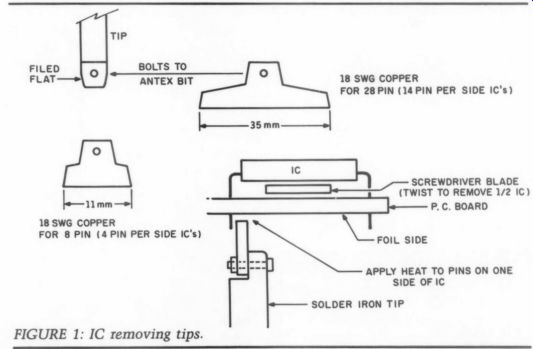
IC REMOVAL TO REMOVE MULTI-PIN ICs from printed circuit boards I have modified one of my Antex soldering iron tips as shown in Fig. 1.
Heat the pins down one side of the IC on the foil side with a screwdriver be tween IC and board. When the solder melts, twist the screwdriver, and one side of the IC will come free from the board. Repeat this procedure on the other side pulling the IC free with your fingers (ouch).
You can remove the 28-pin DAC from the Philips Magnavox CD players in about 30 seconds, without a messy solder sucker or solder wick. Any solder bridges on the foil side can easily be removed afterwards. The ICs don't even get hot. I use a 25W Antex iron.
I know there are professional re movers available for the Antex which remove 8-pin ICs in one operation but not for 28-pin ICs.
A.J. SMITH
Dunedin, New Zealand
MC PREAMP A FEW ERRORS CREPT INTO Part II of my article, “A Moving Coil Preamp” (TAA 1/87). On page 30, second column, the drain resistors should be R10 and R27.
On page 34, the lower part of Fig. 2 is missing. On the same page, formulas 10 and 11 should be:
TIP FILED BOLTS
FLAT ANTEX BIT
| T- R1(8) = A x 1212 (10) (11)
In Fig. 6 D2 should be reversed.
In Fig. 8 R10 should connect to pin 2 of Q5 and in Fig. 12 there should be a jumper connecting Q3 and Q4.
Preamp Setup
General comments. If possible test each amplifier module separately before in stalling it in the chassis. This simplifies measurements, adjustment and, if necessary, component changes. If you have access to a scope, connect it to the out put of the module and check whether radio frequency (RF) oscillations are present. If you have complete audio instrumentation in your workshop, perform the usual gain, frequency response, noise, total harmonic distortion (THD), intermodulation distortion (IM) measurements. Inputs should be shorted un der DC measurements/adjustments.
MC Preamp
Make sure that only group GR FETs are used for the input. Before switching on the module, set P1 to minimum position (CCW). If servo amp Q13 is socketed, don't insert it just yet. Connect the plus and minus 24V regulated supplies to the module and make the following measurements/ adjustments.
1. Check the two zener voltages D1 and D2. They should be 15V plus and minus 5%. Check the output offset. It should be less than plus or minus 0.5V.
18 SWG COPPER FOR 28 PIN (14 PIN PER SIDE IC's) of (TWIST TO REMOVE 1/2 IC) a to Rp
FOR 8 PIN (4 PIN PER SIDE IC's) FOIL SIDE 18 SWG COPPER
FIGURE 1: IC removing tips.
SCREWDRIVER BLADE APPLY HEAT TO PINS ON ONE SIDE OF IC SOLDER IRON TIP
2. Check the current in the input stage by measuring the voltage drop across R10/R27. It should be 2-2.5V, but it is acceptable up to 2.8V. There is no way of adjusting this current, so if the voltage is outside of above limits, you have to select other input FETs.
3. Second stage current is controlled by the current in the first stage and should be 3.7-5.8mA. If 2. checks out ok, then second stage current should automatically be within these limits.
4. Switch off the power and insert an ammeter in series with the plus or the minus supply line. Set the ammeter to the 100 or 200mA position and switch on the supply. Adjust total supply cur rent with P1 to approximately 60mA.
5. Finally, with power once more switched off, insert Q13 in the socket.
Turn on the supply and re-check the output offset. After about a minute, the offset should be less than 2mV. Remember, the servo can only correct about + 0.5V output offset, which corresponds to about 13mV input offset in the 32dB (40x) gain position. If you have more than this, you either have to find input FETs that are better matched or use a servo amp that can work with lower than R32=2k ohm load and can correct larger offsets.
ERNO BORBELY
W. Germany
SEND THE SCA-80-ohm TO COLLEGE--HERE IS HOW YOU can restore the doughty Dyna SCA-80-ohm for use as a premium college dormitory amplifier for a small system. The result is not state of-the-art sound, but equals a good un modified CD player.
First, replace the main and preamp power supply filter capacitor cans, since they are probably old and leaky. Next, order a complete set of polarized electrolytic capacitors to replace those on the preamp and amp circuit boards, plus the two 4.7uF caps between the phono stage and input selector switch. Use the Panasonic HF type from Digi-Key with equivalent voltage and uF ratings. Don't get too creative here, since space is limited and you want to maintain stability. The good HF caps take up all available space.
Second, replace key film caps with polypropylene types. You can replace the input caps for the phono, tone control, and amp boards with 0.82uF, 0.33uF, and 0.33uF caps, respectively.
The last two are exact value replacements. Also replace the RIAA caps (0.056 uF and 0.015uF) with polypropylene and polystyrene caps of equal respective values. Do the same with the treble control caps, 0.22uF and 0.015 uF, respectively. Measure the space avail able for the polypropylene types before you buy them, as space is limited. The Panasonic P-series from Digi-Key are good polypropylene caps in this application, but anything that fits will suffice.
The 0.015 polypropylene types seem to be plentiful at surplus stores between San Diego and Los Angeles.
Replace the wire going from the center wiper of the balance control and its ground wire to the PC boards with Teflon insulated wire. Twist together the ground wire and the center wiper wire and route them over to the boards. You can also replace the phono input and ground wires from the phono input jack to the selector switch with Teflon insulated wire. Solder the pair to the appropriate jack terminals, and twist the pair together along their length. Then wrap this pair around the remaining bundle of input wires on its way to the selector switch. The new wires must be cut longer than the originals to accomplish this. Install a polystyrene phono cartridge loading capacitor of 100 to 120pF or so on each side of the phono input jacks.
Take care with the input selector switch, as it is irreplaceable. If your amp is old and you doubt the condition of the non-polar electrolytic caps on the amplifier PC board, replace them also and be done with it. The big output DC blocking capacitors with the inductors wound around them are rated at 75V but are standing off only about 35V, so they should last a long time. Make sure the fuse is the correct one. Sound Value in Ohio still has most Dyna parts.
I do not advocate changing the bass control caps or any film caps on the boards other than those I mentioned.
This is an upgrade, not an attempt to achieve state-of-the-art sound, so further changes are not worth the effort. The result of my changes is a strong little amp that sounds clean and dynamic and doesn't fall apart on difficult phono playback material.
I would not sell Dyna short on this amp as a non-perfectionist's sound source, and it puts most brand-new mid fi gear to shame. Just lift up the Dyna, then lift up a new mid-fi amp, and you will see why. Its faults are that the last iota of detail in the overtone structure of acoustic instruments is slightly smeared, and the mid-bass sounds faintly bloated. I suppose the very bottom of the bass is poorly controlled, but in a com pact system, this will be inaudible on small speakers. The headphone output is a pleasant surprise. Before you give your aging SCA-80-ohm the heave-ho, find an audiophile with a college-bound off spring, and send the amp off to college in refurbished form. I did, and I have one grateful nephew. I know this because he paid me for the amp. Need I say more? VICTOR STAGGS
San Diego, CA 92109
SOURCES
Digi-Key Corporation 701 Brooks Ave. South PO Box 677
Thief River Falls, MN 56701-0677 capacitors Sound Values/SCC, Inc.
PO Box 551 Dublin, OH 43017
Dynaco spares
Ask TAA
By Gary A. Galo, Contributing Editor
First, a couple of corrections need to be made to my last column (TAA 2/90, p. 47). Due to an editorial misinterpretation, all of my millivolt designations were changed to microvolts. Therefore, please substitute mV for all uVs when reading the opamp offset characteristics. Also, footnote 1 belongs to a portion of that column postponed until this issue. It appears in its correct place below.
NEW CHIPS
At least one other integrated circuit manufacturer has taken an interest in the needs of TAA readers. Jerry Z is, vice president for product marketing at Precision Monolithics, Inc. (PMI) contacted me after reading the Analog Devices and Linear Technology reviews in Ask TAA, 2/90. Jerry sent me a copy of PMI's Audio Handbook, Vol 1. The Handbook contains the latest product data for their SSM line of audio integrated circuits, as well as 19 applications notes. SSM stands for Solid State Micro Technology for Music, Inc., a company formed in 1975 to manufacture ICs for electronic musical instruments. Dan Parks, PMI's marketing manager gave me some history on SSM. The first set of musical instrument chips manufactured by SSM were used in the now famous Prophet 5 synthesizer. The Prophet 5 was the first affordable programmable polyphonic synthesizer and was manufactured by Sequential Circuits. In the early 1980s, SSM's product line was expanded to in clude chips for professional audio equipment, including studio mixing consoles and signal processing devices. PMI purchased SSM in August 1980.
Although I have not had a chance to evaluate any of the chips, several of the devices look promising on paper, including the SSM-2131 FET-input op-amp.
PMI describes it as a pin-compatible up grade to the TL-071 and AD-711 op amps, with a 40V/pus slew rate and a 10MHz gain bandwidth. Two other devices that caught my attention are the SSM-2015 low noise microphone preamplifier and the SSM-2016 ultra low noise differential audio preamplifier. These preamps contain true differential inputs with common mode rejection ratios of 95dB when the gain is set at 100. This makes them suitable for transformerless balanced microphone preamplifiers, and several circuits are included, complete with 48V DIN standard phantom powering. Two of the schematics lead me to believe that PMI's engineers aren't too concerned with the audio performance of the parts used external to the ICs, since tantalum capacitors are recommended for microphone input coupling. Jerry Z is has offered to send any samples I wish to evaluate. I expect to offer hands-on reports on some of these devices in a future Ask TAA. TAA readers may ob tain a copy of the Audio Handbook as well as PMI's latest databook, by contacting the address given below. Mention Audio Amateur and this column when you write or call.
Precision Monolithics, Inc., 1500 Space Park Dr., PO Box 58020, Santa Clara, CA 95052-8020, (800) 843-1515.
CD LENS CLEANING
Audiophiles continue to be perplexed about the need, or lack, for keeping com pact discs clean. Some claim cleaning the discs will significantly improve sound reproduction, while others say the player's error correction circuitry is perfectly capable of dealing with the slight errors caused by small pieces of dirt and debris. I personally believe that if reason able care is exercised in handling CDs, cleaning before each playing is unnecessary. Your experiences may vary, de pending on the sophistication of your player. I have found that as the power supplies in a CD player improve, the effects of disc dampers, CD rings and other methods of stabilization are reduced. I'm not saying that they no longer make a difference, but that the differences are far smaller than if these devices are used on an unmodified player. This is particularly true if you go to the trouble, as did, of building separate power supplies for the analog circuitry and the D/A converter.
Several commercial devices, widely varying in price, are available for cleaning CDs, including those from Nitty Gritty (on the more expensive end) and Discwasher (an inexpensive device which I stopped using since I found that the pad left barely visible hairline marks on every CD I cleaned). A recent article in Stereophile recommended using Armor All Protectant on CDs, claiming dramatic sonic improvement! Unfortunately, that advice was given before any long term effects of the Armor All could be verified. Since that time, users have reported that the Armor All eventually leaves treated CDs permanently fogged and, therefore, unplayable.
Author Sam Tellig now advises removing Armor All from all treated discs and applying Rain X instead.23 Personally, 1 would never recommend any such treatment until the long-term effects can be verified, and that might mean treating a disc or two and waiting a year or more to see what, if any, long-term side effects have resulted from the treatment.
Most of us learned a lesson back in the days of the LP: NEVER be the first kid on your block to apply the latest magic potion to your recordings (remember Sound Guard?). I own 78rpm recordings made in 1905 that still play as well as when they were originally purchased. In fact, they actually sound much better than they did in 1905 since the equipment I have for playing them is far more sophisticated than the hand-cranked, acoustical reproducers of the day. Eighty five years from now, I'd like my grand children to be able to make a similar statement about my CD collection.
With all of this attention, good and bad, devoted to the disc, very little has actually been given to another item equally susceptible to contamination.
That item is the lens inside your CD player. Dust and debris eventually find their way into your CD player, and if you've had your player for more than a few months, chances are that some dust has accumulated on the lens. There is a solution to this problem. AudioSource manufactures a Compact Disc Laser Lens Cleaner (catalog #LLC-1) which I have found to work very well. The CD Lens Cleaner looks like a conventional compact disc, with one exception. The 'playing' side of the CD has a small brush attached to it which cleans your player's lens as the disc spins.
My first thought was that the LLC-1 was simply a blank, unrecorded disc with an attached brush. Closer examination of the instructions revealed that the disc actually does contain a digital code which instructs the player to move the lens under the path of the brush. Using the disc is simple. Simply place the disc in your player, as you would any CD, but make sure the red arrow on the top of the cleaner points toward the CD player. Then press the play button. The CD player will move the lens into position and spin the disc for 10 to 20 seconds.
If disc cleaning has helped, you will probably also note improvement with a clean lens. Beyond the sonic benefits, if you are suddenly having tracking problems with discs that used to play with out difficulty, a dirty lens may be the source of the trouble. I've “repaired”' two players in the music library at The Crane School of Music by simply cleaning the lenses with the AudioSource LLC-1. I suspect that many audiophiles have taken their players to the service shop when, in reality, the only problem was a dirty lens. Two colleagues of mine who are computer users have borrowed my LLC-1 and rescued what were thought to be defective CD-ROM drives. The LLC-1 is highly recommended. Audio Source, 1327 North Carolan Ave., Burlingame, CA 94010, (415) 348 8114. Price: $29.95.
Magnavox 16-bit CD players. First is the Euphonic Technology Compact Disc Player Chassis Stabilizer. Although the Philips-based Magnavox CDB-650 is a favorite modification vehicle, those of us who have chosen the 650 as the basis for a high performance player have long recognized that one of its greatest weaknesses has been its flimsy plastic chassis. Disc dampers and isolation feet have helped this player considerably, in terms of isolating the mechanism from external vibration, and improving the rotational stability of the CD itself.
The stabilizer is a large steel plate, which is attached to the bottom of the CDB-650. Since all of the Magnavox players in this series have physically identical chassis, the stabilizer will also fit the CDB-460, 465, and 560 players.
The chassis stabilizer is a model of precision machining, fitting perfectly into the recess on the bottom of the Magnavox chassis. Mounting is quite simple. Numerous pieces of double-stick fiberglass tape are fastened to the stabilizer at the factory. These have been carefully positioned for the most effective mechanical coupling of the stabilizer to the chassis of the player.
The installer must remove the backing from the fiberglass tape, carefully position the stabilizer into the recess on the bottom of the player, and press the steel plate into place. The instructions recommend placing the player upside down, on a soft towel prior to installation. They also recommend a dry run prior to removing the tape backing, to allow the installer to “get the feel' of the installation process. Once the stabilizer is stuck in place, it will be im possible to move. Eight small Phillips head screws are fastened in place to complete the installation process. It is worth noting that the correct spelling of the screw is Phillips, whereas Philips is the company that manufactures CD players. The name of the screw is misspelled in the installation sheet, but it's certainly easy to get confused when you're using Phillips screws to modify Philips CD players! When I first installed the chassis stabilizer on my highly modified CDB-650, I noticed a subtle, but audible improvement in the sound. Imaging was a little more precise, depth was improved, and there was a slight increase in inner detail. Though I was less than over whelmed, I was not totally surprised.
My 650, with a totally separate power supply for the analog circuitry and D/A converter, is no longer substantially improved by the use of disc dampers and isolation feet. As mentioned above, the effects of these devices are now more subtle. It made sense, to me, that the effects of the chassis stabilizer would also be more subtle on my rather unusual player.
I telephoned Mike Goldfield, president of Euphonic Technology and discussed the situation with him. We both agreed that installing the stabilizer on a more conventional player would probably have a greater effect, and allow me to do greater justice to the product in this review. So, Mike generously sent me a second sample, which I installed on a friend's player, aCDB-650 modified with a Jung-Childress Audio Electronics POOGE-4 kit. My friend, incidentally, is Lorelei Murdie, concert halls manager at the Crane School of Music. She has an excellent audio system, ears to match, and since she hears live, unamplified music on nearly a daily basis, she is better acquainted with the sound of live music than most equipment re viewers. I frequently use her system as a second reference in evaluating equipment and modifications.
On Lorelei's player, the difference was substantial. We immediately noticed that the same kinds of improvements we had heard with disc dampers and isolation feet were taken much further with the chassis stabilizer. The sound stage is wider laterally, imaging is more precise, and depth perspective is greatly improved. The high end of the spectrum is smoother and more detailed. Hall ambience is also improved and dynamics sound less compressed than before.
Clarity of instrumental attacks is more precise, and complex passages in the music show an increase in inner detail.
The stabilizer is a very worthwhile improvement, especially on modified Magnavox players without the special power supply arrangements I have built (which means most of them). Even on my own player, where the improvements were more subtle, I would not want to go back to hearing my player without the stabilizer. Every little improvement gets us that much closer to accurate CD reproduction. To get the most out of your Magnavox chassis, stabilization is a must. I know of no better way to achieve that than by installing Euphonic Technology's stabilizer.
PHILIPS CHIPS
Audiophiles have heard much talk over the past year of the improved versions of Philips' now-classic SAA-7220P/A digital filter and TDA-1541 DAC chips, which first appeared in the CDB-650 and its contemporaries. Although the Philips chip set was considered state-of-the-art when first introduced, it still suffered from a deterioration of resolution at very low signal levels. In this regard, the Philips chips were no different than those made by other manufacturers of CD players. Low level resolution has been a problem digital audio engineers have been working to improve since the first digital audio recorders were manufactured. Many manufacturers have at tempted to solve the problem by marketing players with 18-bits or even 20-bits of resolution. Since the CD is a 16-bit format, this approach won't turn a 16-bit recording into one with 18- or 20-bits of resolution, although the low level resolution of 16-bit discs will be improved.
Philips has taken a different approach, attempting to improve the low level linearity while sticking to a 16-bit for mat. Both the digital filter and the DAC have been upgraded. Although a new filter can be used with an old DAC, and vice versa, the sonic benefits of the new chips will not be realized unless the two are used together. The latest version of the digital filter is the SAA-7220P/B.
Like its predecessor, it is a four times oversampling chip. But, the new chip adds a digital offset to each 16-bit sample. This raises digital zero above the DAC's zero crossing point, which reduces the noise caused by DAC errors to -63dB.
---------------
TABLE 1
TABLE 2--HARMONIC DISTORTION MEASUREMENTS WITH NEW TDA1541A-S1 CROWN DAC AND NEW SAA7220P/B DIGITAL FILTER
TABLE 3--HARMONIC DISTORTION MEASUREMENTS WITH NEW TDA1541-S1 CROWN DAC AND OLD SAA7220P/A DIGITAL FILTER
-------------------------
The top-of-the-line Philips DAC chip is called the TDA1541A-S1. This chip is often referred to as the “S1 Crown,” since a small crown is printed on each chip. The S1 Crown version has been selected for maximum low level linearity. Philips specifies the differential linearity error (DLE) as 0.5 LSB for bits 1-7, < 1.0 LSB for bits 8-15 and <0.75 LSB for bit 16.
Linearity at low signal levels is close to perfect, being within 1dB at a -90dB level.
Sonically, the new chip set does exactly what Philips and Euphonic Technology claim. Low level details in the music are reproduced with greater clarity. Subtle articulations, such as the at tacks of woodwind instruments and tremolos in the strings, are better defined. Hall ambience is more pronounced (it must be on the recordings--the new chips certainly can't manufacture it) and the decay times are noticeably longer.
Here is a case where an increase in clarity has definitely not resulted in a drier, more up front sound. Just the opposite is, in fact, the case. The addition of the new chip set will make other improvements more obvious, since the rest of the player's mechanical and electrical performance will not be hampered by low level resolution problems in the digital circuitry.
Euphonic Technology supplies the chip set with high quality gold-plated, machined-pin IC sockets. Most of the Magnavox players have the old chips soldered in place, although I've worked on two CDB-650s that had a socket for the DAC. The original socket is a cheap tin-plated type. I would remove it and install the new gold socket. For easy removal of the chips and/or sockets, I recommend using the $8.49 Radio Shack de-soldering tool, #64-2060, unless you own one of those $500 motor-driven de-soldering stations (which I don't).
If you've installed the POOGE-4 kit, either from Old Colony or Jung Childress, you already have a new DAC socket and don't need to replace it.
Euphonic's instructions state that under no circumstances should you replace the ICs without referring to the PC board diagram in the Magnavox service manual. This is a good point, since installing a chip backwards will destroy the chip and who knows what else. If you don't have a service manual, use a black permanent felt tipped pen to make a mark on the component side of the board, next to pin 1 of each chip, or next to the notch on that end of the chip.
I routinely check 1kHz, 0dB harmonic distortion, using my CBS or Pierre Verany test discs, whenever I've made a change to a CD player. None of the modifications I've made to CD players ever changed the 1kHz distortion significantly, but I know what it should be in a properly operating player, and a quick check verifies that I haven't made any obvious mistakes. Checking harmonic distortion on a CD player is a bit tricky.
If your distortion analyzer is set for wide-band operation, your distortion reading will be dominated by sampling by-products at 44.1kHz and multiples of that frequency. What you are reading obviously isn't harmonic distortion of the 1kHz fundamental. In order to obtain a more accurate distortion reading, the analyzer should really have a low-pass filter to eliminate the sampling by-product. The Hewlett-Packard HP-544A analyzer I use has a switchable 30kHz low pass filter. I always check the distortion with and without the filter.
After installing the new chips, I was surprised to find the harmonic distortion roughly twice as high, unfiltered, as I had normally observed. Looking at the distortion products on a 'scope, I discovered that the increase in distortion was, in fact, a higher level of sampling by-products at the output of the player.
I was curious as to the cause, so I tried various combinations of new and old filter chips and DACs. The results of my measurements are shown in Tables 1, 2 and 3. From the data, you can see that the new 7220P/B digital filter is actually slightly less effective in filtering the sampling by-products. Note that the wideband distortion measurement reveals the difference in the 44.1kHz components. The filtered distortion measurements show little difference.
You can also see that the S1 Crown DAC combined with the P/B version of the filter gives the player a slightly higher output at 0dB. Although I can't confirm this, the digital offset added by the filter may shift the level of the en tire signal up by one or more bits. This may result in the raising of the maximum output voltage from the DAC. I attempted to get answers to this question, as well as the above distortion change, from Philips, but no one was able to clarify the situation. Needless to say, all sonic changes caused by the new chips are emphatically positive. If you are a Philips player modifier, you really should not be without the latest versions of the filter and DAC chips.
Euphonic Technology, 19 Danbury Rd., Ridgefield, CT 06877, (203) 431 6434.
Compact Disc Player Chassis Stabilizer-$99.95 plus shipping; Philips Chip Set with TDA1541A-S1 Crown DAC, SAA-7220P/B Digital Filter and machined-pin, gold-plated IC sockets--$129.95 plus shipping. (8)
JUST LOOKING
Analog Devices, Inc. has announced a dual 18-bit digital-to-analog converter (DAC) designed specifically for high-performance, multi-channel digital audio applications.
Measured according to EIAT standards, the AD1864 guarantees minimum + 100dB channel separation and maximum 0.0025% (0dB) total harmonic distortion plus noise (THD + N); signal to-noise ratio is typically 108dB. The AD1864 operates from +5 to + 12V supplies, typically dissipates less than 225mW of power and easily interfaces to popular digital filters. The IC is pack aged in a 24-pin DIP and requires no external components to achieve its rated performance.
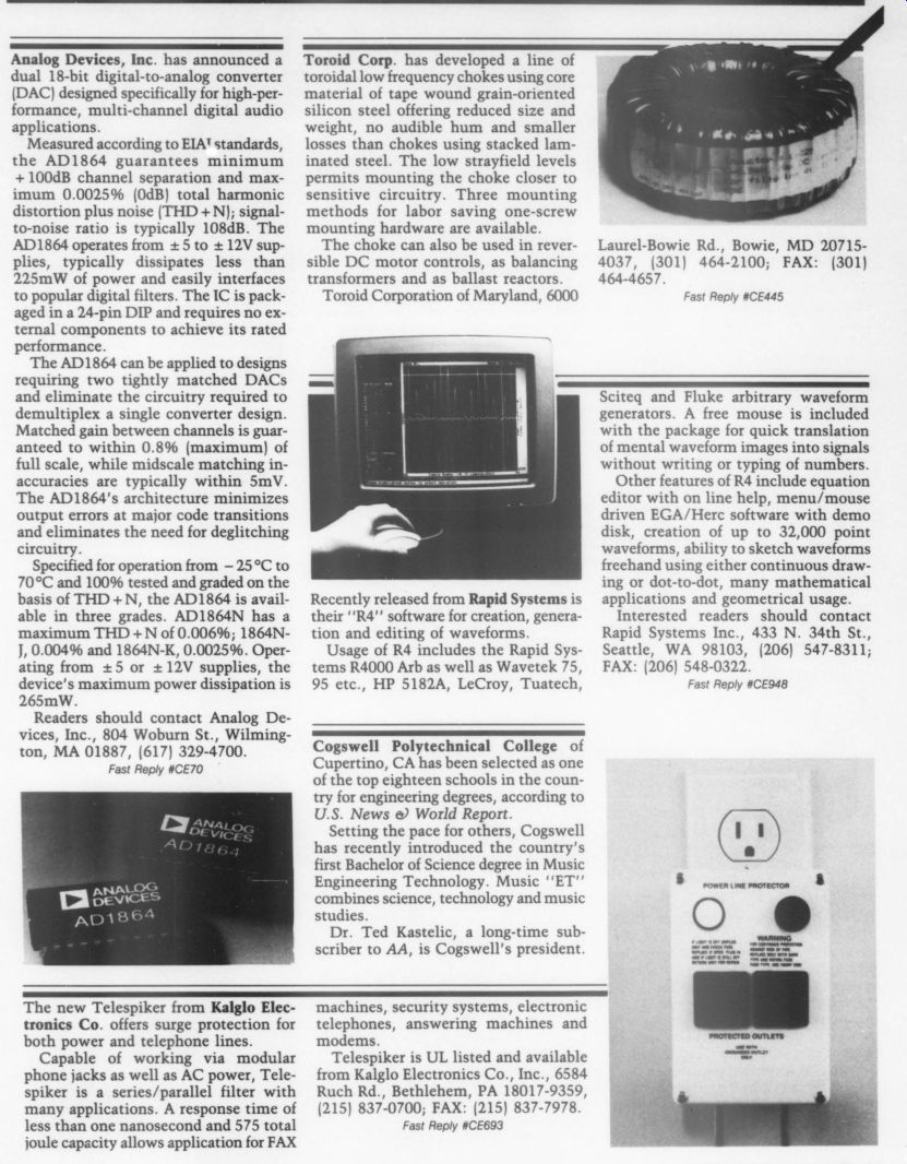
The AD1864 can be applied to designs requiring two tightly matched DACs and eliminate the circuitry required to de-multiplex a single converter design.
Matched gain between channels is guar anteed to within 0.8% (maximum) of full scale, while midscale matching inaccuracies are typically within 5mV.
The AD1864's architecture minimizes output errors at major code transitions and eliminates the need for deglitching circuitry.
Specified for operation from -25°C to 70°C and 100% tested and graded on the basis of THD +N, the AD1864 is avail able in three grades. AD1864N has a maximum THD + N of 0.006%; 1864N J, 0.004% and 1864N-K, 0.0025%. Operating from +5 or 12V supplies, the device's maximum power dissipation is 265mW. Readers should contact Analog Devices, Inc., 804 Woburn St., Wilmington, MA 01887, (617) 329-
The new Telespiker from Kalglo Electronics Co. offers surge protection for both power and telephone lines.
Capable of working via modular phone jacks as well as AC power, Tele-spiker is a series/parallel filter with many applications. A response time of less than one nanosecond and 575 total joule capacity allows application for FAX Toroid Corp. has developed a line of toroidal low frequency chokes using core material of tape wound grain-oriented silicon steel offering reduced size and weight, no audible hum and smaller losses than chokes using stacked laminated steel. The low stray-field levels permits mounting the choke closer to sensitive circuitry. Three mounting methods for labor saving one-screw mounting hardware are available.
The choke can also be used in reversible DC motor controls, as balancing transformers and as ballast reactors.
Toroid Corporation of Maryland, 6000
Recently released from Rapid Systems is their “R4”' software for creation, generation and editing of waveforms.
Usage of R4 includes the Rapid Systems R4000
Arb as well as Wavetek 75, 95 etc., HP 5182A, LeCroy, Tuatech, Cogswell Polytechnical College of Cupertino, CA has been selected as one of the top eighteen schools in the country for engineering degrees, according to U.S. News & World Report.
Setting the pace for others, Cogswell has recently introduced the country's first Bachelor of Science degree in Music Engineering Technology. Music ET” combines science, technology and music studies.
Dr. Ted Kastelic, a long-time sub scriber to AA, is Cogswell's president.
machines, security systems, electronic telephones, answering machines and modems.
Telespiker is UL listed and available from Kalglo Electronics Co., Inc., 6584 Ruch Rd., Bethlehem, PA 18017-9359, (215) 837-0700; FAX: (215) 837-7978.
Laurel-Bowie Rd., Bowie, MD 20715 4037, (301) 464-2100; FAX: (301) 464-4657.
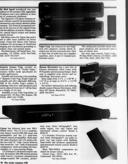
Sciteq and Fluke arbitrary waveform generators. A free mouse is included with the package for quick translation of mental waveform images into signals without writing or typing of numbers.
Other features of R4 include equation editor with on line help, menu/mouse driven EGA/Herc software with demo disk, creation of up to 32,000 point waveforms, ability to sketch waveforms freehand using either continuous drawing or dot-to-dot, many mathematical applications and geometrical usage.
Interested readers should contact: Rapid Systems Inc., 433 N. 34th St., Seattle, WA 98103, (206) 547-8311; FAX: (206) 548-0322.
The Mod Squad introduced two new products at the summer CES; upgradable CD players and a new addition to their line of component platforms.
The Signature CD player features re mote volume control via motorized potentiometers and remote absolute phase inversion. The Prism II incorporates several of the features of the original Prism with the addition of remote volume control, coaxial digital output and display control switch.
Soft Shoes joins the Tiptoe line and is said to offer more stability for better sound. Using Soft Shoes with Tiptoes combines the advantages of vibrational damping and mechanical grounding to produce clean and natural music.
The Mod Squad, 542 North Hwy. 101, Leucadia, CA 92024, (619) 436-7666; FAX: (619) 436-0107.
Tapto Corp. has released its new high tech and computer catalog which includes over 30 new electronic kits. New to their line of audio kits are a graphic equalizer, and a 6 and 12 channel professional mixer.
The catalog also includes many computer products and accessories plus a line of robotic kits.
For your copy contact Tapto Corp., PO Box 44247, Denver, CO 80201, (303) 295-7704; FAX: (303) 295-7708.
Acoustic Science Corp. recently introduced their line of “Studio Traps;” acoustic baffles made specifically for studio applications.
Portable and featuring a free-standing 9” diameter Tube Trap, Studio Traps are tuneable and offer adjustable diffusing.
Half of the Studio Trap’s surface is midrange reflective, half absorptive and can be adjusted from just 6” off the floor to a height of 6.5 feet.
Available at your Tube Trap dealer, or contact ASC, PO Box 1189, Eugene, OR 97440, (800) ASC-TUBE.
Mouser Electronics has a new line of Diecast Aluminum Alloy Cases with PCB guides and mounting flanges. Each case is supplied with screws and interlocking, dust-proof cover.
Sizes range from 3.5”L x 1.38”W x 1.0;”'D to as large as 10.8”L x 2.6”W x 6.9”D.
For further information and ordering details contact Mouser Electronics, 2401 Hwy 287 North, Mansfield, TX 76063, (800) 346-6873.
Carver has debuted their new PRO PHILE series. The CT-6 is a combination remote control FM/AM tuner and preamplifier and the C-5 dual-zone remote control preamplifier. Both sport the same demure size 13.5-inches tall, but are a full 19” wide. Carver believes they avoid the “toy” look of downsized components while providing full functionality in a space-saving design.
CT-6 features a 28-button remote control, 20 random AM/FM station presets with Carver's exclusive asymmetrical charge-coupled FM circuitry, preset/ auto scan, Sonic Holography, four audio inputs, two tape inputs and motorized volume control. Retail is $549.95.
C-5 includes 33-button remote control, Sonic Holography, six audio in puts, two tape inputs with dubbing, bass/treble and loudness equalization and motorized volume control. Retail is $449.95.
More PRO-PHILE components are slated for future release.
Carver Corp., 20121 48th Ave. W., Lynnwood, WA 98046.
++++++++++++++++
Also see: