DEPARTMENTS
- Intro
- EDITORIAL--Should Congress Eviscerate PBS?
- Ask TAA
- AUDIO AIDS
- JUST LOOKING
- LETTERS
Intro
It all started with a modified Marantz 7C preamp dubbed POOGE-1. Eleven years and four levels later, Contributing Editor Gary Galo pulls back the veil from his own contribution in POOGE-5: Rite of Passage For The DAC960, Part I. Beginning here, Gary describes the transformation of the Philips DAC960 D/A converter, a system sure to play a major role in the unfolding drama of POOGE.
If the thought of working with increasingly smaller electronic components leaves your soldering iron cold, consult Blazing Irons. Darcy Staggs' Zen-like calm and nerves of steel inspire us to practice safe soldering.
Richard Moore lights the way as we descend to the basement of audio, the microvolt range. In “Build An A-Weighting Filter, ” the author guides you through building a meter preamp for measuring those low-down signal levels.
Richard Marsh reminds us why we use differential input circuits for balanced and unbalanced signal inputs. Consult "Balancing Differential Circuits" for a discussion of how to improve common-mode rejection and decrease thermal drift.
Do you dine with stacks of CDs on your table? Do you kick over piles of records when you cut through the living room? If your answer is yes to either of these questions, you have just pleaded guilty to one of the seven early warning signs of audio self-indulgence. You could seek professional help, but Bill Ruck suggests you “RACKIT ” instead. Check the review below for details.
JUST LOOKING
With high-power high-current amplification in mind, NAD unveiled the 250W/ channel stereo design power amplifier.
The Model 208's peak current is approximately 100A, dynamic headroom with 8 ohm loads is greater than 3dB, and it produces 600W dynamic power (IHF) per channel at 8 ohm. Low noise is due to a stable bridging mode of no less than 500W monophonic, with dynamic power exceeding 1.5kW. Its toroidal transformer and reservoir capacitance are in excess of 1kuF and includes a soft start circuit.
Its pre-driver topology includes a differential input, followed by an inverted emitter follower buffered cascode stage that can swing 220V peak-to-peak at low distortion rates.
You can unbalance the XLR balanced inputs with a rear panel switch for use with two wire sources. Additional gold plated RCA jacks are included for consumer-style interconnects. Input impedances of 40 k-Ohm (balanced) and 20 k-Ohm (un balanced) present benign loads and allow a single preamp to serve multiple amps.
The Model 208 costs $1,199 and includes a detachable three-core power cord. Its transformer meets all safety standards.
For details, contact Lenbrook Indus tries, 633 Granite Court, Pickering, ON L1W 3K1, Canada, (416) 831-6333.
CR Monarchy Audio introduces its 20-bit digital-to-analog converter which accepts both coaxial and fiber optic digital output signals from quality CD players.
Audio output from the Model 20 decoder is =2V with less than 0.0015% distortion. The critical components-two co linear D/A Burr-Brown converters- attempt to provide perfect linearity at extremely low levels ( - 100dB). Monarchy built its audio output circuitry with all discrete devices with maximum signal purity in mind. The model retails for under $1,000.
For details, contact Monarchy Audio, 380 Swift Ave., Unit 21, South San Fran cisco, CA 94080, (415) 873-3055, FAX (415) 588-0335.
Caddock Electronics, Inc. offers three resistors at three power levels in noninductive designs manufactured in TO-220 style power packages.
The MP 820 Kool-Tab offers a resistance range of 0.05 ohm-10 k-Ohm at 20W at 25°C. The MP 816 Kool-Pak has 16W at 25°C, a range of 0.100 ohm-1 0-Ohm, and is also thermally conductive. The MP 850 Kool-Pak can handle 50W at 25°C in a range of 10-10k, and comes with a cop per heatsink molded into the package.

For details or a free catalog, contact Caddock Electronics, Inc., 17271 N.
Umpqua Hwy., Roseburg, OR 97470, (503) 496-0700, FAX (503) 496-0408.
The XM9 Electronic Crossover Network kit from Marchand Electronics utilizes a fourth-order state variable filter to pro vide high- and low pass functions simultaneously. The precise crossover frequency between 20Hz-5kHz can be set by using plug-in frequency modules. The XM9's signal-to-noise ratio is greater than 110dB and harmonic distortion at 1kHz is less than 0.001%.
The board includes output level and damping controls or can be operated from a remote control panel via the optional XM9 PT, a low cost remote cable, connector, and potentiometer assembly.
Available as a kit, the XM9-K comes with a circuit description and complete assembly instructions for $39.95. The XM9-3KK is a four-board, three-way kit complete with custom cabinet and costs $299.
For more information, contact Marchand Electronics, Inc., 1334 Robin Hood Lane, Webster, NY 14580, (716) 265-4930.
StarPC Instruments introduces its OscPC-100, an XT/AT-based half length card you can use to test and qualify speakers and amplifiers. Use this function generator and frequency counter for stand alone or automatic testing as well as data acquisition applications.
The function generator is capable of producing pulse signals and sine waves independently and simultaneously. The pulse signal with frequency ranging be tween 5Hz-1MHz, is TTL compatible with variable duty cycle between 10% and 90%. The sine wave frequency ranges between 1Hz-25kHz, with levels between 0 and 10V peak-to-peak.
The board comes with dual BNC 1/0 connectors and software running in either command line or menu modes. A software Link Library provides a variety of direct call functions to make it easier for you to interface the card with automatic test or data acquisition systems.
Contact StarPC Instruments, PO Box 64418-4418, Sunnyvale, CA 94086, (408) 739-5117.
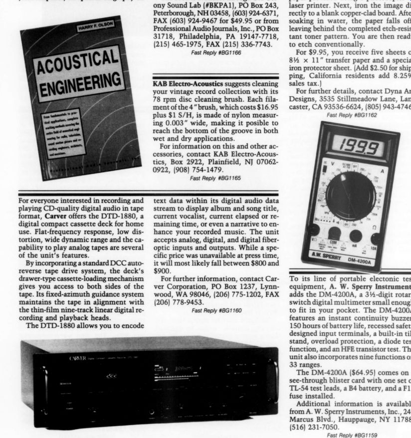
Professional Audio Journals, Inc. announces the re-release of Acoustical Engineering by Harry F. Olson, the first in a series of audio classics reprints. The new edition, printed on acid-free paper, includes more than 700 pages and 500 illustrations, features an introduction by Jesse Klapholz, an updated biography on Olson, and a bibliography of Olson's selected articles published between 1957 and 1980.
Coverage includes loudspeakers and microphones, measurements, sound re production, communication systems, underwater sound, and ultrasonics.
The book is available through Old Colony Sound Lab (#BKPA1), PO Box 243, Peterborough, NH 03458, (603) 924-6371, FAX (603) 924-9467 for $49.95 or from Professional Audio Journals, Inc., PO Box 31718, Philadelphia, PA 19147-7718, (215) 465-1975, FAX (215) 336-7743.
Electro-Acoustics suggests cleaning your vintage record collection with its 78 rpm disc cleaning brush. Each filament of the 4” brush, which costs $16.95 plus $1 S/H, is made of nylon measuring 0.003” wide, making it possible to reach the bottom of the groove in both wet and dry applications.
For information on this and other accessories, contact KAB Electro-Acous tics, Box 2922, Plainfield, NJ 07062-0922, (908) 754-1479.
Dyna Art Designs announces a toner transfer system for creating customized PC board patterns, faceplates, component overlays, and decals without a CAD program.
To use the Toner Transfer System, copy or print your pattern to the transfer paper provided using a photocopier or laser printer. Next, iron the image directly to a blank copper-clad board. After soaking in water, the paper falls off, leaving behind the completed etch-resistant toner pattern. You are then ready to etch conventionally.
For $9.95, you receive five sheets of 8.5 x 11 ” transfer paper and a special iron protector sheet. (Add $2.50 for ship ping, California residents add 8.25% sales tax.) For further details, contact Dyna Art Designs, 3535 Stillmeadow Lane, Lancaster, CA 93536-6624, (805) 943-4746.
For everyone interested in recording and playing CD-quality digital audio in tape format, Carver offers the DTD-1880, a digital compact cassette deck for home use. Flat-frequency response, low distortion, wide dynamic range and the capability to play analog tapes are several of the unit's features.
By incorporating a standard DCC auto reverse tape drive system, the deck's drawer-type cassette-loading mechanism gives you access to both sides of the tape. Its fixed-azimuth guidance system maintains the tape in alignment with the thin-film nine-track linear digital re cording and playback heads.
The DTD-1880 allows you to encode text data within its digital audio data stream to display album and song title, current vocalist, current elapsed or remaining time, or even a narrative to enhance your recorded music. The unit accepts analog, digital, and digital fiber optic inputs and outputs. While a specific price was unavailable at press time, it will most likely fall between $800 and $900.
For further information, contact Carver Corporation, PO Box 1237, Lynn wood, WA 98046, (206) 775-1202, FAX (206) 778-9453.
To its line of portable electronic test equipment, A. W. Sperry Instruments adds the DM-4200A, a 3.5-digit rotary switch digital multimeter small enough to fit in your pocket. The DM-4200A features an instant continuity buzzer, 150 hours of battery life, recessed safety designed input terminals, a built-in tilt stand, overload protection, a diode test function, and an HFE transistor test. The unit also incorporates nine functions on 33 ranges.
The DM-4200A ($64.95) comes on a see-through blister card with one set of TL-54 test leads, a B4 battery, and a F17 fuse installed.
Additional information is available from A. W. Sperry Instruments, Inc., 245 Marcus Blvd., Hauppauge, NY 11788, (516) 231-7050.
In addition to its original Cascade Classic, which utilized 12AX7 tubes in a feedback configuration, Lazarus adds the Cascade Classic MK II ($999), a 6DJ8 tube based circuit with passive RIAA equalization and zero loop feedback.
The new circuit provides a level of dynamics missing in the feedback design.
Controls include a selector switch with six inputs, record select, volume, separate left and right balance attenuators, and stand-by and power switches. Its sensitivity equals 1mV, the input overload measures 600mV on the phono and 25V on the line, noise is - 90dB, and output impedance equals 700 ohm. Power consumption is 30W.
For further information, contact Lazarus, 8130 Coldwater Canyon, N. Hollywood, CA 91605, (818) 982-6477, FAX (818) 982-9308.
Engineering has announced the VI series of automatic A/V switches. The VI allows two video devices (a laser disc player and a VCR) to be connected to a single monitor. It detects which source is delivering a signal and routes the signal to the monitor.
The device can detect either video or audio signals, so it can be used as an expansion input on an audio preamp. It is designed so that if both signals are present, it will give priority to the device on the Video B connection. A sensitivity adjustment allows the VI to filter out noise that can cause erratic switching. A delay adjustment is used to prevent switching on missing signals, such as between tracks on a CD.
The V1 is available with RCA connectors for $89.95 or S-VHS connectors for $119.95. For more information, contact R.F. Engineering, Inc., 9215 Lowell Blvd., Westminster, CO 80030, (303) 430-8281, FAX (303) 430-4023.
Analog Devices now offers the SSM-2143 balanced line receiver as a companion to the SSM-2142, a balanced line driver.
The unit is a fully integrated and balanced receiver system for audio and industrial designs requiring high immunity from EMI. Combined, these two units form a compact solution to driving and receiving audio signals over long, noisy cable runs.
Two gain options make the monolithic SSM-2143 flexible enough for applications requiring a gain of one half, where its input stage is designed to handle signals as large as + 28dBu. A gain of 2 can be realized by reversing the in put and reference connections. With a gain of -6dB, it offers 90dB common mode rejection at 60Hz and 85dB at 20kHz.
For details, contact Analog Devices, Precision Monolithics Division, 1500 Space Park Dr., Santa Clara, CA 95052, (408) 562-7513.
The Rockford Corporation's two new units, the Model 915 Preamplifier and 945 Preamplifier/ Tuner, are part of Hafler's new Series 9000. Both models feature a pure Class A all-discrete pri mary signal path that exploits the tube like sonic qualities of high gm J-FET topology.
The 915 Preamplifier ($700) features CMOS-FET and relay switching to allow optimum circuit flow for direct audio path and isolation between signals.
The 945 Preamplifier/ Tuner ($600)
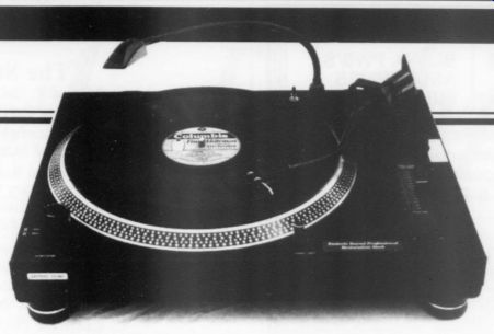
Esoteric Sound is offering a six speed selectable phonograph player for LP discs. The V3 Professional Restoration Deck plays discs at 33, 45, 71.29, 76.59, 78.26, and 80 rpm. Other features include adjustable tracking and anti-shaking force, dust cover, and a solenoid brake for stopping platters instantly- all for $475. It operates from 120V AC or 240V AC @ 50/60Hz.
For more information, contact Esoteric Sound, 4813 Wallbank Ave., Downers Grove, IL 60515.
PCBoards version 1.7 of PCBoards Lay out now supports Hercules, CGA, EGA, VGA, and Super VGA. The software runs on any IBM PC or compatible with 384K RAM and one disk drive. With its 1x generated artwork, you can make your own films for producing high-quality prototype boards; 2x artwork is generated for production quality. You can produce single- or double-sided boards.
A stand-alone program, it has two companion programs-PCRoute 3.3 (the autorouter) and SuperCAD 3.0 (a schematic capture program)-which have also been upgraded.
PCBoards Layout, PCRoute, and SuperCAD each sells for $99. The PC Route upgrade is $35 and SuperCAD + costs $199. To download demos, call (205) 933-2954.
For more information, contact PC Boards, 2110 14th Ave. S., Birmingham, AL 35205, (205) 933-1122.
features defeatable tone controls, a standardized infrared remote control, and an FM section with a double balanced mixer.
Each item is available in two styles: 17 ” black Eurostyle or 19 ” silver rack mount able. The Series 9000, providing high sonic performance, is backed by Hafler's seven-year warranty.
Contact Larry VanSickel, Rockford Corporation, 613 South Rockford Dr., Tempe, AZ 85281, (602) 967-3565, FAX (602) 894-1528.
Editorial
Should Congress Eviscerate PBS?
Some members of Congress would like to cut all funding to the Public Broadcasting System, others want to set up a government agency to control its programming decisions and still others would like to pull the allocations for Public TV stations and force all of them to find cable outlets.
This may be the final proof we probably do not need that the Congress of the United States has lost its marbles. It has become increasingly apparent that a majority of the citizenry of this country are disgusted and disillusioned with Congress.
And to make matters worse, many of the more responsible members of Congress are getting out because of discouragement with the system.
Congress has sunk to a new low in a history that has never been exactly illustrious from early times. Public esteem has slipped to the lowest level in my memory, which goes back to the first election of Franklin D. Roosevelt in 1932.
The reasons for these proposals to shackle, cripple or destroy Public Television have a number of understandable, probable causes. The news reporting on public TV is more incisive, digs deeper and reports more accurately than any other source. The public media have embarrassed Congress more often than any other news channels. A PBS reporter broke the news of the sexual harassment charge in the Thomas hearings.
Many commercial interests would love to get their hands on the allocations presently assigned to the public TV stations. Capitalistic greed in the TV industry does not need further encouragement, to say the least.
The forces who would like to destroy or ignore the 1st Amendment guarantees protecting free speech and expression in the United States are hard at work to censor nearly any form of communication to their special standards and, to them, Public TV is one of the worst offenders.
Cable TV is a pay-for-view medium. Do we suppose Sesame Street would be seen in the rotting tenements of the large cities of this country if Big Bird were accessible on a pay channel costing $18 to $25 per month? Our literacy rate is bad enough without losing this single force for education that has disseminated the basics in a marvelous form to a generation of children.
Public TV now reaches 98% of the public freely and the content of its broadcasts is some of the best, not just in the USA, but in the world. The only cable channels, other than the news types, which are flourishing draw heavily from pro grams developed either by the BBC or US Public TV. The major networks are dying of “bottom-line ” program managers, losing several percentage points of listenership each year. Do we need room in the TV channels for more of this kind of crass, profit-oriented, violent, lowest common denominator, silly non-leadership? The Congress of the United States appropriates far less per capita for non-commercial broadcasting than most of the major western countries. Outside the US we are regarded as mindless bumpkins because of our attitude toward public support for the arts and especially public broadcasting. Our Congress has been niggardly for years about the arts, never recognizing even the cash value of the investment of public funds in the quality of our cultural life.
We probably ought not to be surprised that this gadfly PBS has become a royal pain in the Congressional sitting equipment. If so, isn't that a really vital reason all of us should support PBS? Think of how much worse things might be if people like MacNeill/ Lehrer were not doing their remark able nightly work.
Public Television serves as a daytime resource to 80% of the public schools in the US while we are at our daytime work. But of course, the Congress can scarcely be expected to be too concerned about that since the youngsters won't be voting this year. They are doubtless more concerned about their free haircuts, free postage and their private, no-fault banking arrangements. They were also more concerned about shoving such issues as the Savings and Loan disaster under the rug for three years before the situation became really messy. And several house members were kept busy propping up the credibility of some of the worst of the bankers until it was too late to do anything but load the bills of the robbers onto the backs of the US taxpayers.
If you agree with me about even a part of the value of Congress investing a paltry 80 cents per year, per citizen, in the Public Broadcasting System, I hope you will bombard your Senators and members of the House of Representatives with an avalanche of protest.
I can think of a great many fundings I would like to see stopped to save money: I am very strongly budget-minded about the CIA, the Secret Service, the proposed multi-billion dollar addition to the Pentagon and all of the funds for prop ping up brutal, anti-democratic dictators in at least a dozen tin-pot countries around the world.
The framers of the United States Constitution had good reason to know that even the best government in the world is potentially the natural enemy of the citizenry. George III was the most visible example, but the army of mindless bureaucrats behind him were a real and permanent part of the danger, as well. Even the Continental Congress might not have imagined the lengths to which today's CIA and IRS are prepared to go. Our task as citizens has always been to keep the 'enemy' in check. Obviously we have not been doing a good job. Unless we learn, and soon, the mess in Washington is going to get bigger and worse and more ex pensive. Whatever your politics, please vote, even if you haven't much stomach for your choice. At least you'll have a platform for beefing later.
And whatever you do, and even if you flatly disagree with these personal opinions of mine, let your representatives in Congress know your views on the issue of Public broadcasting. -E.T.D.
ASK TAA
By Gary A. Galo, Contibuting Editor
RECENTLY, I TRIED some high performance metal film resistors that sonically out-perform most others I've heard. Until this discovery, Roederstein (Resista) MK 2s were my resistors of choice- I used them in my CD player and pre amp. They suffer from one performance hampering drawback, however; their leads and end-caps are made of steel, a permeable metal.
Vishay resistors meet these requirements and are gaining a reputation for outstanding audio performance. Unfortunately, Vishay won't sell factory direct and distributor prices range from $5 and $25 each, depending upon quantity and value. I find this to be unreasonable.
Reader Paul Kelly recommends the MK 132 resistors from Caddock Electronics. A little investigation led me to Caddock's senior application engineer, Greg Grey, who sent me eight resistors to replace those in critical locations in my preamp line stage.

The MK 132s are 0.5 W resistors and look like small film capacitors. They are 0.29 “-square, 0.095 “-thick, with radial leads. Although tolerances are available down to 0.01%, I opted for 1% samples.
What's more, Caddock resistors are made of non-magnetic materials. Grey described the following manufacturing process in a letter:
Caddock begins the process by filming and firing a metallization onto an alumina substrate. Then, they screen the resistive material, Micronix, onto the substrate and fire it at high temperature. Soldering tinned copper leads to the metallized portion of the substrate comes next. They trim this assembly to a resistance value and then place a number of these assemblies into a mold be fore introducing silicon molding com pound. The final product undergoes testing again to ensure resistance-value ac curacy before being marked and pack aged for shipment.
Sonically, the Caddock resistors are superb. With my preamp line stage's newfound inner detail as proof, I place them ahead of the Roedersteins. The high end is more open and instrumental timbres have greater harmonic accuracy be cause these resistors allow more high frequency information to get through.
Your first reaction might be that the top is just a bit brighter than before, but it is also smoother and less harsh.
I haven't found any resistors superior to the MK 132s. Caddock sells factory direct, with no minimum order-good news for audio amateurs. Pricing for values of 1000 to 99.99K, 1% tolerance is as follows:
1 to 9: $3.45 ea.
10 to 24: $2.30 ea.
25 to 99: $1.53 ea.
100 to 249: $1.28 ea.
In quantities of 25 or more, these resistors are not outrageously expensive.
While it may not be cost effective to replace every resistor in a circuit, by being selective, you can significantly improve performance for a reasonable cost.
In a preamp circuit, gain-determining resistor pairs are important as are any within the signal path.
Resistors in an RIAA equalization circuit are, of course, critical. If you are extremely fussy with RIAA resistors, you could order 0.01% tolerance, but bear in mind, capacitor tolerance invariably determines the accuracy of an RIAA circuit because they usually vary more than the resistors.
Caddock also manufactures film power resistors. Loudspeaker builders might find these worth investigating. In a loudspeaker crossover network, you can use expensive polypropylene capacitors, and Perfect Lay or Sidewinder inductors. Unfortunately, the crossover performance will still be limited by the cheap cement-cased wirewound power resistors still so prevalent.
Caddock's Type MV low-resistance power-film resistors use Micronix films in a patented non-inductive design. They are available with up to 10W ratings, with 1% tolerances. The high-end loud speaker industry needs better quality resistors to complement the already fine capacitors, inductors and internal wiring normally used. While I haven't tried the MVs myself, they are certainly worth investigating.
Caddock resistors are available from:
Caddock Electronics, Inc., 17271 North The ILP Solution IN 1986, TAA ran a turntable speed- control article of mine (TAA 1/86, p. 7).
Reader James Grimmer wrote that he hasn't been able to locate a supplier for the ILP toroidal transformers and power amp module specified.
Fortunately, all of the ILP components are still in production and most are easily available from Active Electronics.
They do not list all ILP products in their catalog, but can special order any they do not stock. Everything needed for my speed control is listed in their catalog, except the 1A010 transformer. If Active cannot deliver within a reasonable amount of time, you can substitute the 2A010.
Active Electronics, 11 Cummings Pk., Woburn, MA 01801, (617) 932-4616.
A Kinder, Gentler PCB
A READER FROM, Rockville, MD, Lai Chang Ling, has a problem with his Magnavox CDB-560. After replacing the 5532 op amps supplied with the player, the 560 stopped playing AAD and ADD discs. Now it only plays DDDs. He's mystified. So am I! There aren't any digital codes recorded on a CD identifying the original master tape as either analog or digital. Thus, your player has no way of knowing whether the CD is DDD, ADD or AAD. Something else must have happened to this player during the modification process, and its selective playing of DDD discs is just a coincidence.
A few years ago, I had a similar problem with a CDB-650. After modifying it, the 650 wouldn't index any disc. I care fully reheated all my PC-board solder connections on the SAA7210 decoder chip and associated components, and the player worked fine.
The circuit board traces are quite fragile. It's possible that a hairline crack developed during the modification process.
A careful look at the board is in order, perhaps using a magnifying glass, to spot a break in a PCB trace.
It is entirely possible some dust found its way onto the laser pickup while the player was open. I recommend cleaning the laser with Audio Source’s LLC-2 Compact Disc Lens Cleaner. The LLC-2's two angled brushes provide an improved lens cleaning method. Every one should clean their CD lenses from time to time. The AudioSource disc works very well.
Mr. Ling also requested a source for SK175 and SJ55 power MOSFET transistors, which I interpreted as 2SK175 and 2SJ55. As far as I know, there is no US source for these transistors. If any readers know where we can find them, please let me know.
AudioSource, 1327 North Carolan Avenue, Burlingame, CA 94010. Many audio dealers carry the disc, as well.
Electronic Arts
IN TAA 2/90, reader Charles L. Crawford recommended a book called The Art of Electronics by Paul Horowitz and Win field Hill. I found a copy at Clarkson University's engineering school in Potsdam, NY but I decided to wait to review the latest edition. Well, the wheels of progress sometimes move more slowly than I'd like, but here it is.
The second edition of The Art of Electronics is one of the most impressive books ever to cross my desk. This massive reference offers over 1,100 pages of electronic circuit design information. I'll begin by telling you what this book does not include. It's not a book on basic electronics theory. Although Horowitz and Hill have included some introductory chapters, they move rather quickly and assume conceptual knowledge possibly beyond the beginner's ken.
If you are still learning, I recommend Heathkit's Electronic Fundamentals by Philip E. Wheeler. It is the best text on basic electronics I've seen (TAA 1/90, p. 46). With the solid foundation pro vided by the Heathkit text, you'll be ready to understand and use the material in The Art of Electronics.
The title of this book offers some in sight on how the authors view circuit de sign. They seem to believe-and rightly so-most books on electronic theory do not teach you how to design circuits.
Horowitz and Hill maintain that a solid theoretical background is only half the battle. Circuit designers already have a solid textbook-based theoretical back ground. The best of them also have an intuitive understanding, or “feel, ” for what makes a first-class circuit.
It's virtually impossible to give adequate coverage to every topic covered in a book of this scope. It would require a review almost as lengthy as the book itself. A concise overview will have to do.
The Art of Electronics is rooted in the very late twentieth century. It does not include vacuum tube circuits or theory- it is a solid-state circuit-design reference manual. Horowitz and Hill extensively cover discrete transistor circuits before moving on to common transistors.
The authors often discuss circuits not found in conventional electrical engineering texts. Have you ever tried to find an explanation of cascode circuits? Your search is over. Horowitz and Hill give ample space to the subject, with examples of both bipolar and FET implementations. They devote a large portion of the book to IC op amps including amplifiers, filters, and voltage regulators.
An entire chapter is devoted to amplifier noise.
A substantial portion of The Art of Electronics is devoted to digital circuitry. The chapter discussing digital electronic basics is outstanding. The following chapter entitled “Digital Meets Analog ” provides a superb A/D and D/A conversion overview. Extensive cover age of microcomputers and microprocessors is also included.
A Good Read
Audio amateurs will find the chapter on construction techniques interesting, al though most of it describes digital over analog construction. Although not a primary concern, the authors even offer coverage of radio frequency circuitry. Several of the appendices are useful, especally those covering oscilloscope theory and proper schematic drawing practices.
They did, however, neglect to mention computer programs available for schematic drawing, such as OrCAD.
The Art of Electronics is loaded with schematic illustrations-an average of two per page-going beyond just showing examples. These illustrations not only offer practical insights into how the circuits work, but also ways to transfer this knowledge to real-world circuit de sign. To this end, each chapter closes with two sets of examples called ‘Circuit Ideas' and “Bad Circuits. ” The lat ter is both amusing and helpful. If you heed its advice, it helps you to avoid mistakes.
Horowitz and Hill's approach is non mathematical, using math as a tool only when necessary. Their writing style is in formal, and they have a sense of humor.
They have obviously gone to great lengths to avoid intimidating the reader, and are successful. For example, when necessary to indicate current direction, the authors chose conventional rather than electron current flow. No matter which method you prefer, you will not find the concepts behind them confusing.
Considering the book's length and the extraordinary number of superb illustrations, the price is extremely reasonable.
Many publishers charge more than $100 for books of this size and scope. The Art of Electronics is an indispensable addition to my electronics library. Thanks again, Charles Crawford, for bringing it to our attention.
The Art of Electronics by Paul Horowitz and Winfield Hill, 2nd Ed. New York, Cambridge University Press, 1989. 1,125 pages, hardcover, $54.95 plus $2 S/H from Old Colony Sound Lab, PO Box 243, Peterborough, NH 03458, (603) 924-6371.
AUDIO AIDS
REVAMPED CD PLAYER I FINALLY BUILT up enough nerve to go in to my four year old Focus CD player to investigate adding an analog power supply. This relatively simple modification improved the sound significantly. I was shocked by how few POOGE modifica tions were in this player, considering its price was 2.5 times the stock player's.
But enough on circuits, I am getting away from the real reason why I am writing. It's damping. Here are three modifications.
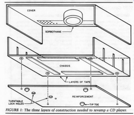
FIGURE 1: The three layers of construction needed to revamp a CD player.
The Focus CD player has a Sorbothane foot placed under its cover just to the right of the transport (Fig. 1). If you al ready have Sorbothane feet in a tripod arrangement on your component this is a good location for the unused one.
The CD bearing damper uses simple physics. It's expensive considering its simple construction, is easy to install, and removes CD hardness, resulting in the added smoothness of a high quality analog front end.
Since the plastic chassis is very flimsy, I added a 15 x 11 x 1/16 “ piece of stain less sheet metal to the bottom. Plexiglass or other sheet metal would work just as well. Drill screw holes through the chassis feet into the metal to bolt it all together. I filled the resulting 1/4, ” gap between the chassis bottom and the added sheet with three layers of 3/32” two sided rubber tape (in four or more columns). This makes the chassis bottom as rigid as the old Dynaco bottom plate.
Drill two 1/4 “ holes to access the turn-table hold-down screws and one 3 3/8 ” hole for a PC board screw. Bolt them together and ground it. You'll have a very rigid chassis with shielded bottom. Add three Tiptoes and you're in business.
My CD player now out performs my VPI MK III, Premier FT3, Grado 8MR turntable.
LLOYD LANE Philadelphia, PA 19133
TDK DEVICES
READER JOHN BUSCHMANN recently raised a question regarding the effectiveness of the “TDK Digital Noise Absorbers' (available from the Herrington catalog for $14.95/pair (800) 622-5221). I have tested a pair of these devices. They are a split ferrite core with a plastic case which encases any normal conductor (power or interconnect). As with the trial homemade unit I covered in my letter to Mr. Buschmann (TAA 1/92, p. 64), 1 cannot vouch for the effectiveness of the devices. On AC they do not affect the common mode spikes, and are not as effective as the Cor-Com devices or others of that ilk. It's really a giant ferrite bead, with the label 'Digital' added to sell them. I cannot vouch for how they affect the interconnects, and I cannot detect any change, whatsoever from their use.
It may be of interest to tell you how I made a ferrite trial before the TDK devices came to hand:
I solicited the aid of a friend who is a “Rock-hound ” and an amateur lapidary. Because ferrite is so brittle and difficult to handle; it is a ceramic-like block with magnetic iron particles; my friend sawed the core using a saw for cutting gems. The stone cutter blade is a thin copper disc, impregnated with diamond dust, and the saw includes a pump system to keep a diamond and water slurry pouring on the saw at all times. Cutting was clean and quick.
The block was then drilled, using a brass tube and more diamond slurry on his drill press. This was outfitted with a pan to collect the slurry and a circulating pump to supply the slurry for the cutting tube. In less than five minutes we had a center hole. We then halved it lengthwise and made a second unit for the test.
The halves were fastened to both interconnects and AC cords using nylon tie-wraps. It had virtually no effect on the sound, even with noise injected into the AC.
Since ferrites are easily saturated at high frequencies, I believed high frequency noise might be reduced. I could neither see any noise reduction on the memory scope, nor could I detect any reduction by ear when using my system with the homemade test ferrite devices, nor later when the TDK devices were used. A 1/2 hp brush-type electric motor was connected into the same AC power supply as my sound system, and while an EMI/RFI (Cor-Com) device identical to the one I sent Mr. Buschmann did audibly eliminate the motor hash, including the start/stop hash, there was virtually no similar effect with any of the ferrite giant bead devices.
I mentioned ferrite beads in 'About Noise’ (TAA 2/91, p. 10). These were tiny devices about 3.5mm in diameter and have a center hole that will handle 20-gauge wire. They are about 3mm long.
L. B. DALZELL, El Cajon, CA 92020
Product Review
RACKIT SYSTEM: A BETTER MEDIA HOME
Reviewed by William F. Ruck
RACKIT System, Per Madsen Design, PO Box 330101, San Francisco, CA 94133, (415) 928-4509. Ask for a brochure containing pricing and ordering information.
WHILE MY WIFE Siobhan and I have been busy improving our audio hardware, our collection of records and CDs has continued to grow. We eventually filled all available storage space in our home. A friend described our situation as “out of control.” During a visit to a friend's home, we saw a RACKIT. A good looking, cleverly designed, flexible storage system. I promptly visited the Per Madsen Design showroom and bought a unit.
The basic unit is a four-wheel dolly foundation supporting the other modules. The record rack holds 100 records and the CD cabinet drawer holds 90 to 180 CDs. Single- or double-width holders can be stored in any order. Stacking the modules 6' high accommodates five record modules (500 records) or five CD-180 modules (900 CDs). The modules are interchangeable. An oak table top is available.
Initially I didn't consider wheels on the bottom, until my wife pointed out they make the unit mobile when vacuuming the carpet. Also, without emptying the modules, the stack disassembles and moves easily. Each record rack can be handled fully loaded and weighs about 55 pounds. This eliminates the chore of boxing and replacing your audio collection for each cleaning session.
The dolly and record rack are solid oak and the CD drawers are oak and red plywood. This system is precision crafted and handsomely finished in a Danish oil, natural color. Some assembly is required for the record racks, but all you need is a 4-MM hex bit (supplied), an electric drill, and a hammer. The CD drawers arrive assembled.
Per Madsen Design offers modules to fit CD3, 3.5 ” floppy disks, audio cassettes, video cassettes, and 45 rpm recordings. Work is in process for a modular equipment system with similar features. I viewed the prototypes and was impressed. While working on other units, they use RACKIT to store and move material.
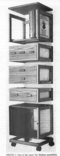
PHOTO 1: One of the many Per Madsen assemblies.
LETTERS
Unfortunately, two “bridges ” developed in the Williamson/Watling Preamp 90 circuit board on page 13 of TAA 1/92. These are present at pins 5 and 4 of IC7 and pin 4 of IC6.
-Ed.
-----------------
MORE ON FEEDFORWARD
I ALWAYS LOOK forward to the interesting things I find in each issue of TAA. Your 'Feedforward Error Cancellation' (TAA 3/91, p. 10) is the most innovative project I believe I have seen since I started subscribing. My letter is actually about measurement methods.
I am intrigued by the idea of deriving values below the signal-to-noise capability of test instruments. In trying to interpret the results of my own not-so trusty HP302A wave analyzer (AFC won't always hold the tuned frequency) I have been uncertain what use could be made of residual meter readings.
In assessing the improvement in distortion through your feedforward circuit you derived harmonics smaller than the residual of the HP302A by taking the square root of the difference between the squared residual and the squared residual plus distortion measurement. If you can help me understand this I would appreciate it. If I am correct, this is what you did, using the example of the second harmonic.
1. Measure second-harmonic of main amplifier without feedforward.
2. Measure second-harmonic at out put of complete feedforward amplifier.
3. Remove injected signal and take a residual measurement on the HP302A at the output of the complete feedforward amplifier.
4. Derive a corrected second-harmonic value by taking the square root of the difference of the squares of the measurements in steps 2 and 3.
If I have followed you correctly, could you explain whether this was an approximation which you made assuming that sine wave components and noise add in the same manner? (I assume residual measurements are usually noise in the measurement device and the measured circuit.) If this is considered valid, did you also correct the value shown for second-harmonic without feedforward in the same way using residual on the meter at the main output? You suggested improving the HP302A signal-to-noise capability by using a notch filter. How would this be done? Would it involve any calculated corrections similar to those you used?
LARRY GLENN, Eau Claire, WI 54701
Ronald Bauman replies:
I appreciate your kind words about my feedforward cancellation article. In it I established a lower bound on the distortion cancelling capability of the feedforward amplifier. The test instrument residuals to which I referred are harmonic distortion residuals-not noise residuals. To look at signals below noise, you must integrate for some time over a very narrow bandwidth. The residual harmonics of my instrumentation were well above thermal noise.
Residual harmonics are a combination of the wave analyzer and signal generator harmonics and were measured by connecting the signal generator, an HP200C to the wave analyzer through an attenuator. In this case, signal generator harmonics are actually part of the desired signal and will not be cancelled by the feedforward amplifier. The IM (harmonic number) data in Fig. 3 and Table 1 of my article give a truer indication of cancellation capability.
To address your question about the use of a notch filter to improve signal-to noise (actually, I used the term dynamic range), let's first understand what limits the dynamic range of the distortion measuring device. Here I'm using the term dynamic range to describe the ratio of the largest signal to the largest of harmonic distortion or noise, whichever is larger. In our case, the harmonics are much greater than the noise so the dynamic range is harmonic rather than noise limited. The distortion measuring device in our case the HP302A, uses amplifiers ahead of the narrow band spectrum analyzer filter. This amplifier produces harmonic distortion (and noise) in much the same way as the amplifier under test.
To reduce its residual distortion (and thereby improve its dynamic range) use a notch filter that attenuates only the fundamental signal but not the harmonics. The output of the notch filter would be connected to the input of the wave analyzer, ahead of the analyzer's first amplifier. The input of the notch filter connects to the output of the device under test.
You can build a fixed-notch filter for any fundamental frequency you like using conventional twin T or LC notches.
However, creating tuneable notches is not so easy. In the article, my oblique reference to “more exotic techniques' refers to some work I did a number of years ago on applying feedforward techniques to tuneable RF notch filters. I am developing an audio feedforward tune able notch filter that would extend the dynamic range of our HP302As (or other harmonic, wave, or spectrum analyzers) to at least 130dB (that is, they could mea sure distortion products greater than 0.00003% of the fundamental). With this technique the dynamic range would approach the noise limit. But, I don't want to steal any thunder from this work just now for I hope to publish my article about it in the future. Please stay tuned.
REACTION/PREFERENCE
PURCHASED TAA 1/92 primarily to look for ads for PC Schematic/PCB programs.
I have found those neat little stick-on circles and lines for board patterns are no longer available, and supplies of chemicals scarce or outdated.
This issue of TAA was a bit of a disappointment. The first article on the Dyna appearance upgrade seems to regard the electronic upgrades as a complete secret.
Must I purchase Glass Audio to find that out? The second article reminded me why I didn't buy TAA 4/91. Here is a preamp of even less merit than Doug Self's 'Precision Preamplifier,’ of which my criticism led to a roller-coaster three year letters-column battle in Electronics World & Wireless World. No, I am being unkind--at least this Williamson preamp does not use electrolytic coupling capacitors.
As John Curl constantly reminds me (following his spirited defense of me in EWeWW), there is little point in having a hobby building things if one emulates a cheap commercial product. One needs to soar, to try to fabricate a Ferrari, not a Pinto. This Williamson amplifier is not as good as a Rotel RC 850 preamp for an audio amateur. Ten 5uF polypropylene capacitors will transform the $250 Rotel into a relatively graceful swan, and you get a case with professional lettering and an MC input as well.
That is, if you really have an overpowering urge to own an IC op amp preamp in the first place. I don't. Mr. William son doesn't even comment on the sound of his creation-very wise.
The seminal articles on amplifier de sign have been those of Malcolm Hawks ford. He has written in both Hi-Fi News and the Journal of the Audio Engineering Society (the best article is in Vol. 36, No. 4). Erno Borbely has also used these approaches in his 1991 preamp updates, at least those parts dealing with correct methods for cascoding. Oddly enough, Hawksford's circuits are predated in actual purchasable designs from the Accuphase company in Japan. Their literature shows the circuits, and also the famous single-ended FET buffer which people are just waking up to, all dating from 1986.
Finally, your reviewer Andrea Clark seems to be completely out-of-sync with TAA. Following her spirited defense of her review challenged by Marjorie Williamson (an English woman of highly unusual characteristics-she can apparently cook and read at the same time), Ms. Clark retreats into “There's nothing wrong with my system, and if you heard it, you'd realize that too ” when replying to Mr. Staggs. Did he or the readers deserve the implicit “tweaks are a waste-of-time ” response'? I offer a tip for those wishing to hear a different CD sound. I am lucky, my very good friend owns a hi-fi store where I hear various pieces of equipment in detail. I bought a Meridian 203 DAC a year ago after POOGEing my Rotel 855 to the limit, except for IC op amp changes (and no, I did not like the sound caused by biasing those 5532's into Class A with FETs as per TAA, sorry). The Meridian was great, and held up well to com petition from Bitwise, Audio Alchemy, and EAD. The EAD was better, but not by much.
Also, about a year ago, I was intrigued by the sound of the Kenwood DP-4030 CD player, and last fall purchased one.
It is a 1-bit DAC, but I cannot determine my power amp under construction, a Class A unit of 50W/channel (160W into 2QAB) of 1988.
BRUCE ARMSTRONG, Waverly, NS, Canada
The Editor sent me a copy of your letter since he knew it would amuse me. Normally, I would consign such missives straight into the waste bin, especially when it is from someone who reads my copy on a bookstand. Do you sample food in a restaurant before sitting down for a meal?
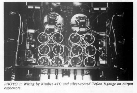
PHOTO 1: Wiring by Kimber 4TC and silver-coated Teflon 8-gauge on output capacitors.
whether it is really MASH or bitstream However, the removal of the exception ally cheap and nasty electrolytic output caps transforms the unit. Care must be taken with DC offsets of up to 40mV by balancing the input resistors to the integrator op amp. The treble is not great In any case, the real sleeper is the Ken wood DP 5030. It has a Sony DAC, rather than NPC, and a glorious sound once it is POOGE'd. I have sold my Meridian, since the Kenwood is far better.
In fact, all Philips-type units now sound to me as though they have no transient response. The Kenwood sounds as though it is a distortionless source, a most unusual and gratifying experience which makes listening to music an absolute delight. And I own a Koetsu Sig nature Red! I now prefer CD for the most part.
Included are views (Photos 1 and 2) of You reveal the characteristic vacuity of the average tweaker, completely taken in by commercial hype. If you had the faintest understanding of design techniques in audio, then you just might have recognized the completely innovative circuitry that was described in our article ('A New Control Preamp: Back to the Future,’ Parts I and II, TAA 4/91 and 1/92, pp. 10 and 12, respectively). In fact, if you can find just one commercial product that employs the equalizing circuitry I describe, or the feedback-type gain control, or the variable low-pass filter, then I will take everything back.
It does have electrolytics in the signal path as well, but I doubt if you under stand where. Proper design is something more than using expensively hyped components. We did not mention how it sounds since it performs like any other properly designed preamplifier with similar facilities and as good as the source material allowed-but one that the reader can make, and cheaper.
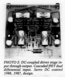
PHOTO 2: DC-coupled driver stage in put through output. Cascoded JFET dual differential input. Servo DC control 1988, 1987, design.
My colleague, Alan Watling, once went to an illustrated lecture by Dr. Hawksford, whom you hold in high es teem. He reported the quality of the sound reproduction was execrable and the lecture content incomprehensible.
Finally, I can also confirm that my wife is a superb cook and is quite capable of reading while a meal is in preparation.
Moreover, she has far better ears than I have. We both listen to music-not equipment.
SUPER-PLAYER STATUS
I HAVE COMPLETED modifying my Magnavox CDB-465 employing many of the changes outlined in 'Improving the CDB-650's DAC' (TAA 1/91, p. 10), i.e., POOGEing the analog and power supply sections, new AD 827 op amps and the DAC clocking jitter mod. I also etched a small piggyback board and replaced all of the bit filter caps around the DAC with the 1.0uF + 0.10uF + 0.01uF P/P combo as per your recommendation. I did not include the I/V out put zeroing feature, electing instead to retain the 10uF + 0.01uF output caps (Wonder-Caps).
The DAC clocking jitter modification was accomplished very easily by installing one short jumper and cutting the trace between pins 2 and 4. It seems to me that this feature was intended to be connected in this manner.
I am confused by a letter by Walt Jung in the January 1991 Stereophile concerning this modification in which he indicated that the jitter-free feature was not included in the 1541A S1 Crown chip.
Is this mod applicable to the 1541A-S1 Crown or not? I would like to upgrade my 1541 to the S1 device as it is reported to be significantly improved in low level linearity, an area of my player's performance still lacking.
As far as the power supply improvements are concerned, I built the KG-5, 15V 1.5A (103VA Avel-Lindberg toroidal transformer) supply as designed by Galo/Jung/Markell. Frankly I was disappointed in the lack of sonic improvement when the new supply was connected to the analog section. I subsequently went back to the original supply. I'd be interested in your experience in this regard, and some suggestions as to the best construction techniques for an output power supply in this CD application., e.g., transformer-only output with AC to KG-5 inside player, versus DC to player from separate supply, best type of connectors and connection techniques, etc.
Thanks for your great articles and enthusiasm. I am enjoying my CDs as I had never thought possible as a direct result of the prodding I received (from your article) to go just a little bit further with the 'most for the least’ mods that I had previously performed. I am definitely a novice but I have gained a great deal of confidence in my ability to up grade my electronics without destroying them. As a matter of fact I feel like I know the circuit board of the DCB-465 so well that I could almost modify it in my sleep!
ROBERT WILSON; Mobile, AL 36608
John Allgaier replies:
I am pleased that you have tried so many of my suggestions from the article. I too like the Analog Devices AD827/847 op amps. Believe it or not, but even with Wonder-Caps as the output coupling stage, a servo circuit with no series caps as couplers is audibly better. Use about 10uF as the integrating cap (I use 10uF bipolar aluminum paralleled with 1uF and 0.1uF poly) for truly deep bass.
Using 0.1uF or even 1uF as the integrator affects the bass range quite noticeably.
Regarding Walt Jung's letter to Stereophile, he stated that the TDA1541A (all incarnations) did not incorporate the jitter-free mode. Walt quoted a Signet ics-Philips data sheet and an applications note covering the DAC. I had a data sheet dated six months after the one Walt had and it still showed the feature.
Enabling the jitter-free mode made such an improvement (increased ambience, lower noise floor, greater clarity, and a “gelling ” of the sound) that I believe the capability is still in the silicon. Walt and I both contacted Philips independently (Walt, if you read this, did you ever get an answer from P. Shah?) but I never got an answer-they were going to check with Holland. I recommend trying this mod--my Crown version is going great as it wont damage DAC if done properly.
As to the power supply, the KG-5 is a very competent supply so I would look to distribution as a source of your lack of enthusiasm. I mounted my trans former outside to the back of my player and ran the lower AC voltage into the supply PC boards. Remoting the supply and running the DAC into the player puts long leads in series with the sup ply and raises its impedance dramatic ally (dependent on wire diameter, construction of wire, proximity to ground, impedance of ground, number of connections, etc). I used five strands of 30-gauge wirewrap Litz style per Jung in the POOGE articles to hook up the DC to the circuits. The supply I used was from Borbely's preamp article with the board re-laid out with smaller footprint.
Anyone with a basic understanding of electronics, minimal soldering skills, and meticulous habits can improve their player to “super-player ” status. Thank you for believing in yourself and my improvements.
BUF-03/KG-5 SITUATION IN THE NOVEMBER 1991 issue of Stereophile magazine, Corey Greenberg de scribed a buffered, passive preamplifier powered by the Linear Technology based power supply I described in my column, Ask TAA (4/90, p. 47). The regulator circuit was designed by Walt Jung,
---
PREVIEW
Glass Audio Issue 3, 1992
An Octal Tube Preamp
Vacuum Tube Op Amp
Tube Design Primer
A 50s Purist Amp
-----------
... at the time a staff scientist for Linear Technology. As a result of experimentation, Walt and I added refinements which included the dual rectifier bridges, selection of the power transformer, and final value of the output filter capacitors. The schematic in that column showed resistor values for regulated voltages of + 15V, which are fine for most preamp-level circuitry. I also provided resistor values, in the text, for +-12 and + 18V.
Although it is flattering to see our work endorsed in the pages of Stereophile, one aspect of Corey Greenberg's implementation of our supply causes me great concern. His passive preamp is based on PMI's excellent BUF-03 high speed IC buffer, which has an absolute maximum supply voltage rating of +- 18V. Mr. Greenberg has set the regulated voltages at +- 18V, using the resistor values I provided.
Normally, it is not a wise design practice to operate any device at its absolute maximum supply voltage. However, to confirm (or deny) my suspicions, I called James Wong, Applications Manager at PMI. Mr. Wong had already read Green berg's article and was equally concerned.
He said the BUF-03 should never be operated at its absolute maximum rating.
The BUF-03 has a very high quiescent current. With +- 15V rails, supply current is 18mA, which results in a total power dissipation of 540mW. According to Mr. Wong, the BUF-03 was designed with + 15V rails in mind. As long as a heat sink is placed on the device, this level of power dissipation is not a problem.
With the rail voltages raised to + 18V, power dissipation increases to over 660mW, since the BUF-03 supply cur rent is 18.5mA at these voltages. Mr.
Wong told me the resulting high level of heat dissipation is not safe for the BUF-03 and could result in thermal run away and failure of the device. Under such conditions, even before actual failure, performance parameters can change significantly, including DC offset (this may be the greatest concern). According to PMI, +- 15V should be considered the rail voltage limit for the BUF-03. Ad justing the regulators for nominal + 15V rails allows a safety margin which ensures that slight variations in the divider resistor tolerances will never push the device close to, or over the edge. When I wrote the column on the KG-5 supply, I assumed other designers would select regulated voltages appropriate to the de vices they intended to operate.
The KG-5 supply can be built from scratch. Audio amateurs may purchase the transformer and parts themselves, using my 4/90 column as a guide. You may even wish to fabricate your own PC boards, or construct the regulators on a perfboard, as I did for the first three I built. For a single source for all parts and the board, Old Colony Sound Lab sells the complete KG-5 kit (KG-5, $129), or the blank circuit board alone (PCBG-5, $15), for those who wish to purchase the other parts and transformer separately.
A “board plus parts ” package is also available for $74.95. The builder has a variety of options, all producing a power supply that performs as we intended, as long as you follow the guidelines in my column.
If builders of Mr. Greenberg's preamp use any of the power transformers I recommended, all they need to do is change R2 and R4 to 10.5k to lower the rail voltages to +-15V. I only recommended transformers with dual 15V or 18V windings, including the Avel-Lindberg D3030. The D3030 has dual 18V AC windings, but under light static-load conditions and high-line voltage, these windings actually deliver over 20V AC.
This will produce around 28V of rectified DC. The 13V drop across the reg ulators is within safety limits. I have tested this regulator with a load drawing 55mA of current, using the D3030 transformer. Using a Variac, I fed a high line voltage of 125V AC to the trans former. After several hours of operation, the IC regulators with 5W heatsinks were quite warm to the touch, but they weren't uncomfortable.
Unfortunately, Mr. Greenberg recommended an Avel-Lindberg D3031. It has dual 22V AC secondary windings, and will be closer to 24V AC under normal loading conditions. Rectified, these AC voltages produce nearly + 34V DC. Also, the voltage drop across the regulators actually exceeds the regulated voltage. The resulting heat dissipated by the regulators is excessive. For this reason, builders who've already purchased all the parts listed in the Stereophile article not only should replace R2 and R4, but they should also purchase a new power transformer to ensure safe operation of the regulators. If you've used any of the transformers I recommended, only the resistors need changing.
Finally, I specified 1.5k bleeder resistors for testing purposes. I also noted, at Walt's suggestion, that a minimum load of 50mA is desirable for the lowest regulator output impedance. I recommended adjusting the bleeder resistors to compensate for any difference between the recommended 50mA and the current drawn by the circuitry. A pair of BUF-03s draw 36mA, leaving 14mA. With +- 15V rails, a 1k, AW resistor from each rail to ground is close enough.
This is a subtle point, but one which should be addressed if you are to achieve the optimum safe performance of this circuit. It is also important to consider the static 50mA load in the context of the thermal constraints mentioned above.
In another vein, the characteristics I consider unique to the KG-5 regulator circuit are:
Separate bridge rectifiers for the positive and negative regulators.
The selection of the transformer, although this doesn't actually appear in the schematic (TAA 4/90, p. 47).
Very large output filter capacitors. I don't know of any data sheet specifying an output filter cap of more than one-tenth of the value we use. The same holds true for input filter caps in most data sheets.
This may be the most important: The divider resistor values are around ten times the values listed in most data sheets. This allows a higher value for C2 and C9 which, in turn, provides higher ripple rejection and lower out put impedance at low frequencies.
Check the National Semiconductor data for LM317/337 regulators and you'll find 10-25% of those we use.
The Linear Technology data sheets specify similar values.
GARY A. GALO; Potsdam, NY 13676
AMPLE AMP'S BOX
I AM VERY IMPRESSED with Chris John son's attention to detail in his Showcase article, “An Ample Amplifier ” (TAA 3/90, p. 45). 1am in the process of building the Borbely Servo 100 and have a couple of questions.
I want to construct an enclosure similar to yours for my amp and noticed you used 6061-T6 aluminum alloy. From the picture, it appears you built a frame out of spare aluminum rails and then bolted top, front, bottom, and sides to the rails.
What size aluminum was used for the rails? Did you attach rails to the bottom, top, etc. and then, holding everything together, drill holes through the other piece and bolt them together? In other words, is there a square block of aluminum in the corner where any outside piece meets at 90° ? What thickness did you use for the back, bottom, and front?
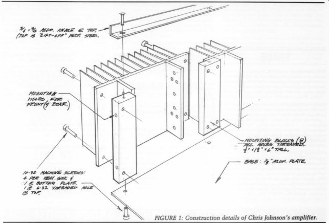
FIGURE 1: Construction details of Chris Johnson's amplifier.
Any additional comments you could pro vide on the construction would be greatly appreciated.
You refer to ‘. ..the six side-mounted heatsinks are simply ¼-inch thick aluminum plates, with fins I spliced together with aluminum blocks.’ Did you buy these heatsinks and then hold them all together with the long aluminum blocks ...
--------------
PREVIEW Speaker Builder Issue 4, 1992
A Prize Transmission Line Speaker
Alignment Jamming
An Electronic Coil Winding Counter
Stalking F3
Double Chambered Isobarik Bass Speaker
----------
... or did you make them out of 1/4 inch aluminum? If you bought them, please give a source. If you made them, please provide the details. They look very professional and I've had a hard time finding heat sinks like the ones pictured.
Thank you for your time and assistance.
MARK FLORIAN Austin, TX 78746
Chris Johnson replies:
Thanks for the compliment re my amplifier project. I've enclosed a sketch of the mechanical details used in construction.
The heatsinks were obtained from a now out-of-business surplus store here in New York, so I'm not sure where you might find units like this now. The “secret ” to the entire assembly are the eight aluminum blocks. They are fabricated from 6061-76 stock, 1.5 ” x 0.5 ” in cross section. I used a band saw to cut them to a “rough ” length and a disc sander to “grind ” them to a precise length. A drill press was used to drill the holes, which were then tapped to accept the machine screws. The bottom plate, rear plate, and front were directly mounted to these blocks with ten 32 x 0.75 “ machines screws. The “top ” of the amp is fabricated with a sheet of perforated steel and simply rests inside a % x % channel. The channel (Fig. 1) was mounted to the blocks with six 32 Screws.
In effect, each ‘side assembly' consists of three heatsinks and four aluminum blocks. The torque generated by the large machine screws yields an absolutely rigid assembly.
-------------
Also see: