by H. W. Hellyer
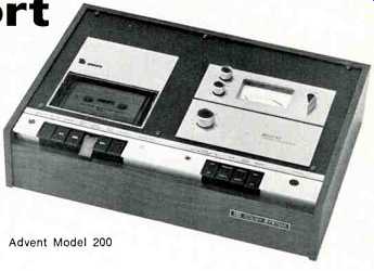
---Advent Model 200
A MAN would have to be blind and deaf to be unaware of the growth of cassette--and cartridge--loading tape recorders over the past couple of years. They will not-as some of the more hysterical reviewers have implied-completely oust the reel-to-reel machine. Each has its own virtue; each its particular application. Cassettes have come to stay, however, and the number of tape decks using a variation of the patented Philips system has swelled alarmingly (or satisfyingly depending on which side of the fence you sit). The real audio-buff tends to look down at packaged tape, whether cassette or cartridge. He is making a mistake. Whatever system you choose, the standard of modern tape and the improvement of modern mechanics, allows you to enjoy the best of good music at home, on the move, anywhere. As Bert Whyte found (Audio, April 1970) for lower level listening "at apartment house level" and for sheer convenience, cassettes could not be matched. He noted the excellence of the tape in the DGG cassettes that had just come to his notice, and commented on the hiss which impaired the dynamic range when played at high levels through a high fidelity system.
Our Bert, still tingling from his train-catching tramp through the snow with the Stellavox, may have overlooked the fact that the DGG tapes were recorded to CCIR characteristics, and he does not mention what equipment was used for his replay experiments.
He is right, though, to say "Until this bug-a-boo of hiss is conquered, cassettes will never realize their potential." Right, too, to point out that progress was and is being made. Recent researches by Ed Canby have given us a clue to the future of the cassette. With Dolbyized recordings and super-quality tape, we shall get to the standard it is now possible to reach with disc and with reel-to-reel recorders of the better quality at 1 7/8 in./sec.
Maybe sooner than you think.
Now is as good a time as any to take a more intimate look at the cassette-loading mechanism, with its special maintenance problems. Cartridges we shall have to leave for later-there are still too many ways of doing the same thing where multitrack operation is concerned. But the cassette mechanisms are all based on an original Philips' design, however much succeeding manufacturers try to trick it up. This design found its way to the market in 1963, called the EL 3300, in Europe. The U.S. invasion followed three years later reversing the usual trend.
Cassette Recorder Design
Design of a portable tape recorder is not just a matter of whittling down a larger machine. Nor is it simply achieved by arranging a battery supply and fitting a handle! There are special circuits for drive control and some ingenious ways of compromising and combining RECORD, PLAY and INDICATOR circuits. In addition to this, modern techniques of electret microphone construction permit the building of a really compact portable with no trailing leads.
Power supplies present few problems. With motors capable of achieving sufficient torque even from as little as 3 volts, and overall consumption during RECORD or PLAY limited to a few milli-amps, battery-stowage space need not be great. The present tendency is to add a simple transformer and rectifier circuit, with rudimentary smoothing, to allow operation from a.c. supply. But the price for this added convenience must often be paid in an increase of noise level during recording.
Some authorities disclaim this as a drawback. "Most recording is done in the field," they argue, "so the a.c. facility can be used on replay." But the crunch comes when one has to dub off those precious cassettes onto open reels for convenient and economical storage. Then, the use of batteries is expensive and the use of an a.c. supply can still raise the noise level more than may be tolerated. Perhaps the solution lies in the rechargeable cell-slowly gaining ground among enthusiasts.
Normal method of power-supply switching is a leaf spring actuated by the insertion of the a.c. adapter. In some cases, extra power is available by this action, and in more than one design there are three alternative power-supply circuits, adapted for use with internal cells, from an automobile battery and from house current.
But I exceed my brief as much as the exuberant Bert did and must come back to basics. And nothing could be more basic than the motor supply. Without it the recorder is just so much trash. And with it, unregulated, the recorder may be little better. As batteries run down, so the motor slows, falters and finally stops, and this is not a regular decline. It is considered better for the supply to drive the motor at full available power as long as can be, then stop. This is the way power supplies are tailored nowadays. The regulator ensures a supply until the batteries are no longer capable of sustaining the load, and then the regulator cuts in and the motor cuts out. We shall see later how this can be done.
Simple motor-control circuits start with the Zener diode, preventing the applied voltage from rising above a pre-determined amount, then combined with an adequate overload capability for long life. In the most refined designs they have sensors and differential amplifiers, monitoring the speed and regularity of the tape transport. One or two examples we shall discuss have performance specifications well up to professional rating.
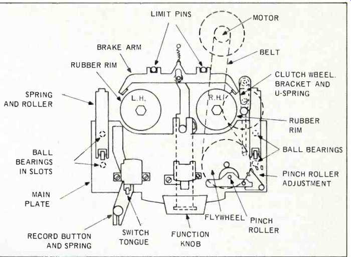
Fig. 1-Showing schematic layout of major components of Philips-type cassette
recorder.
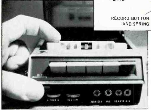
Fig. 2--With cassette partly ejected and the tape run through to its leader,
the pressure pad and spring and the cutaway portions of the cassette are
visible.
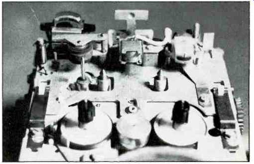
Fig. 3--Showing upper portion of Philips-design deck, looking forward toward
the head and function buttons.
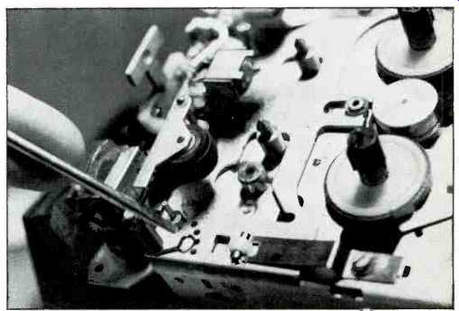
Fig. 4--Pinch roller adjustment is indicated by the screwdriver.
The flywheel and capstan spindle have been removed.
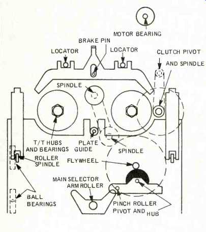
Fig. 5--Showing lubrication chart. Apply light oil to rotating parts and
medium grease to sliding parts.
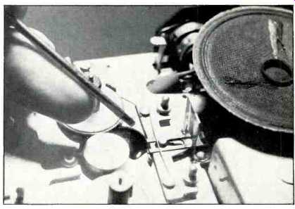
Fig. 6-The transverse spring, indicated by the screwdriver, aids engagement
of the brakes, which are lugs on the bracket.
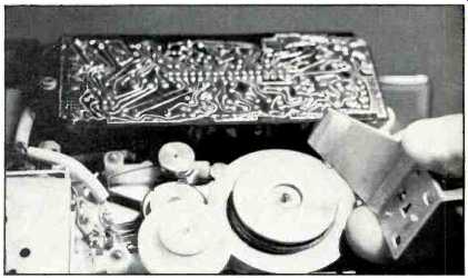
Fig. 7-Showing the underside of the deck, with main-drive belt and lower
flywheel bearing removed.
For most cassette tape recorders, a deck layout such as that of Fig. 1 is quite usual. Small turntables with sprung, splined tops engage the hubs of the cassette and locating pins minimize the amount of lateral play. As the run of the tape across the front of the cassette (oxide coating outwards) cannot be altered, it is necessary to advance the heads and pressure roller every time we select PLAY or RECORD. (See Fig. 2, where a partially ejected cassette has been run back to its transparent leader to demonstrate the apertures and recesses in the front of the cassette.) The darker shading of this traveling plate in Fig. 1 makes this easier to understand but does not show the various clearance slots and abutments that are needed. These can be studied better in Fig. 3, where an alternative view of the stripped deck is given.
The first thing evident is the need for a shaped cutaway for the capstan spindle and elongated holes for the cassette locating pins. These are shown in greater detail in Fig. 4, where we also become aware of the simple spring adjustment for pinch-roller pressure. The outer arm of this spring is fitted to the end of the roller arm. The nearer the roller the captured end of the spring is placed, the greater the inward pressure.
Also plainly visible in both these shots and indicated in Fig. 1 are the very important springs and rollers which guide the head plate forward correctly when RECORD or PLAY are selected. The plate runs on ball bearings, which click into detents at the limits of travel. Again, simplicity is the aim, and the designers earn a salute for the effectiveness of their baby. Once or twice, I have had trouble with the sliding plate, but the cause has generally been a bit of dirt gumming up the spring rollers and allowing them to override. The solution is obvious!
Lubrication
Well, maybe not so obvious, for the most frequent failures I encounter are caused by over-indulgence in lubricants. Cleanliness comes first. My old Nanny used to tell me it was next to Godliness--on some tape decks it is next to impossible! On the Philips design only a steady hand and a fine brush may be needed. Lubrication is limited to a drop of tight oil on rotating parts and a smear of medium grease on sliding parts. To make life easier, I include a rough chart (Fig. 5) showing the main lubricating points on this deck. Please note--the motor should never be oiled. Any attempt to do so will result in noisy operation since the brushes will pit. When motors get sluggish, they can sometimes be completely stripped and cleaned and the bearings lightly lubricated. Whether or not you do so depends on your time/economy scale. Some of these motors defy reassembly anyway. A drop of oil on the top bearing is enough.
Reverting to the deck assembly, we see that the head plate is pushed forward by a roller operated by the function selector arm. This is held by a nylon circlip. In several other places in this deck we find such securing devices and they have one drawback they dislike being disturbed. If one is servicing any great number of these cassette machines, it is wise to lay in a stock of spare circlips and washers.
The brakes are mere lugs on the brake bracket, engaging the rubber rims of the turntables. The bracket is held off by a spring attached to the rear part of the spring blade which holds the cassette into place, illustrated in Fig. I but removed in Fig. 6 to show more clearly the transverse spring that aids the engagement of the brakes. Possibly because of the enclosed nature of a cassette and a consequent lack of freedom of the supply "spool" to run on, very little trouble is encountered with brakes, and the most frequent service problem I have had with the variants of these mechanisms has been a fouling of a pin in the forked slide.
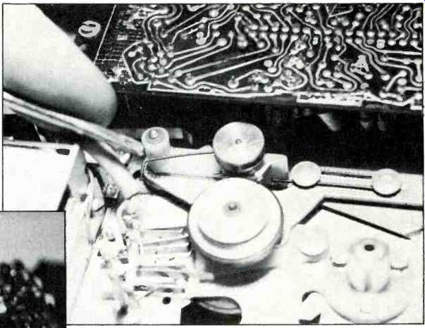
Fig. 9--Fast-wind action depends on two pulleys and the exact setting of
the spring indicated by the screwdriver.
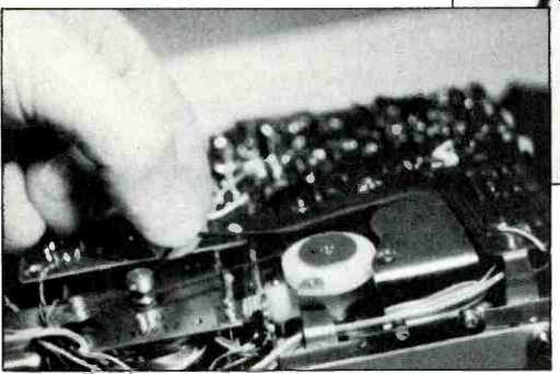
Fig. 8--Belt changing is easy, but the alignment of the motor pulley, flywheel
and clutch grooves is important.
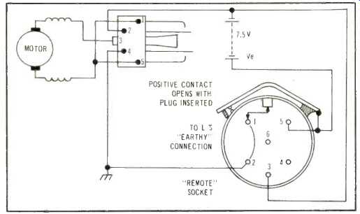
Fig. 10A--Supply and switching circuit of early Philips models.
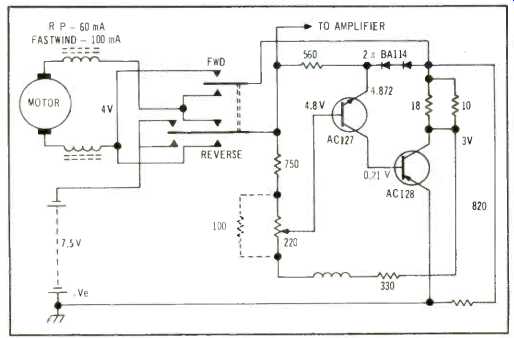
Fig. 10B--Supply, switching, and regulator circuit in later Philips-design
cassette recorders.
Clutch Mechanisms
Not so fault-free are the clutch mechanisms. however. The main-drive belt (another vulnerable item) couples motor pulley and flywheel and runs against one section of the clutch assembly. With a motor of 3,000 rpm, this flywheel turns at 6 cycles per second to give the rated speed of 1 7/8 in./sec. tape travel. Looking at Fig. 7 which has both belt and lower flywheel bearing removed, we can see the three main parts of the clutch design. Nearer the camera is the clutch wheel, driven by the belt. This is mounted on a bracket with a hook spring applying regulated inward pressure, and the two sections of the clutch have a felt disc between for transmitting the necessary torque, but allowing slippage. The upper section drives the spindle that engages the rubber rim of the take-up turntable. This can be seen in Fig. 3. Adjustment to the required 120-150 grams is made by bending the spring. Not so evident is the need for alignment of motor pulley, clutch wheel, and flywheel for correct transmission of torque. The flywheel bottom bearings, simple pads as shown in Fig. 7, permit some adjustment, and quite often the bracket fixing holes are slightly elongated. The motor seating, especially after replacement with an alternative type, may have to be packed up so that the lateral and the vertical alignments, of the motor pulley are accurate. There is a small amount of adjustment, the pulley being secured by a screw to the shaft, as shown in Fig. 8.
Other parts of the clutch mechanism that need attention are the fast winding pulleys. A look at Figs. 3 and 4 shows how this is done above the deck, with a fairly large (greater circumference, higher speed) driving pulley between the two turntables. Below the deck, all is not so simple, and to aid explanation I have further stripped the basic Philips model, removing belt, flywheel and clutch wheel with its bracket (Fig. 9). The secondary roller bearing above the deck, i.e., the drive pulley mentioned before, is driven from below by a small belt in the groove of the drive wheel nearest the camera in Fig. 9.
This drive wheel engages the flywheel via its own rubber rim, and a fairly fast, direct drive is ensured, with enough of a safety slippage given by the belt coupling. Reversal is simply made by changing the polarity of the supply to the d.c. motor. The sneaky part of this assembly is that rod spring indicated by my screwdriver blade and rather obtrusive finger in Fig. 9. It should just touch the mount bushing in the FAST WINDING mode but be clear of the limiting bracket (part of the case-mounting assembly). During PLAY, however, the spring may touch this bracket but has to be clear of the mount bushing.
This whole operation is bound up with the movement of the main operating arm and the coupling to the leaf switch that can be seen in Fig. 9. There are several alternative versions of the switching, and care must be taken when replacing the switch that not only the right type is obtained, but also that the motor and supply circuits match, up. With so many variants, it is easy to waste your money.
As a guide, no more than that, I have included a couple of the relevant drawings. These are neither schematic nor purely representative: They have been dreamed up in the past to put a couple of apprentices on the right road and may come in helpful for any readers who own cassette machines and are hesitant to tackle their maintenance. Figure l0a shows the original type of switch fitted in the Philips decks (the EL3300) with its wiring to motor and supply, and also the wiring of the 6-pin switched socket which is important for remote control and a.c. current operation. In Fig. 10b the later type of switch is shown and with it the simple regulator panel used to hold the motor to its correct voltage during RECORD and PLAY. More elegant regulators have been used by other firms, but some, such as Sony, eschew them altogether, preferring to use a more powerful motor and more strictly controlled mechanical design.
Next: Regulators
(adapted from Audio magazine, Jan. 1971)
Also see:
Tape Transport Maintenance--Part 6--Brakes (Oct. 1970)
Tape Transport Maintenance PART 5/Heads, Guides, and Pressure Pads (Apr. 1970)
Choosing a Tape Recorder (Apr. 1972)
Build Your Own Tape Eraser (Jan. 1971)
= = = =