by BASCOM H. KING
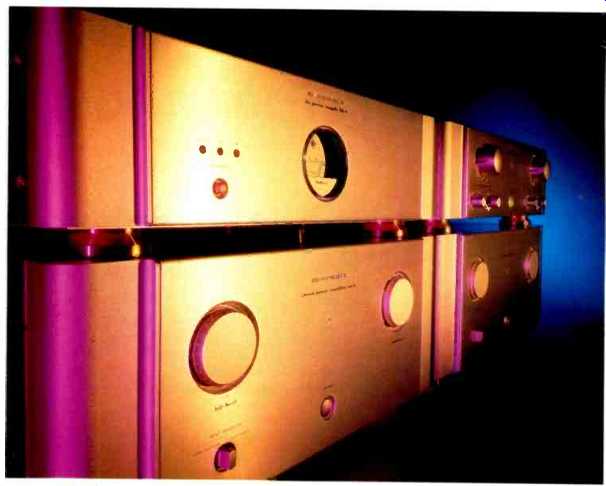
The SM-5 amp and the SC-5 preamp are the first Marantz components that I have ever formally reviewed, and what impressive gear this is! There are those who feel that battery power supplies are best for audio equipment, and someone at Marantz evidently agrees, because the SM-5 and SC 5 share the BB-5 battery power supply. This supply, included with the SC-5, will also be available separately, which will enable SM-5 amps to be used with other preamps. The SC-5 preamp is completely powered from the BB-5, but the SM-5 amps use the BB-5 only for front-end power; the amps' output stages are powered by a conventional supply derived from the AC line.
In the SC-5 preamplifier, wide-band width HDAM (High-Definition Amplifier Module) gain blocks, made of discrete devices, are used instead of the usual ICs for all amplification functions. Unusually, the volume control is said to be implemented actively rather than passively. Instead of a balance control, separate level-trim controls, adjustable in 1-dB steps, are used for each channel. Unbalanced inputs are provided for a CD player, two tape recorders, five other line-level sources, and MM or MC phono. Addition ally, there is one pair of balanced inputs, a pair of balanced out puts, and a multipin connector for the BB-5 power supply. The front-panel controls, all but one of which are rotary knobs, fall into two groups: selector switches (for input, phono mode, and "Rec Out") on the left and volume and level-trim controls on the right. At the bottom center of the panel is a pushbutton on/off switch.
============
AMP
Power Output: Stereo mode, 100 continuous watts/channel into 8 ohms or 200 watts/channel into 4 ohms; bridged mono, 400 continuous watts into 8 ohms.
Dimensions: 17 3/8 in. W x 8 3/4 in. H x 17 3/8 in. D (45.4 cm x 21 cm x 44.7 cm).
Weight: 70 1/2 lbs. (32 kg).
Price: $7,000 each; requires BB-5 power supply.
PREAMP
Dimensions: 17 7/8 in. W x 5 1/2 in. H x 13 3/4 in. D (45.4 cm x 13.8 cm x 34.7 cm).
Weight: 29.8 lbs. (13.5 kg).
Price: $8,000; includes BB-5 power supply.
BATTERY POWER SUPPLY
Battery Life With one SM-5 amp and one SC-5 preamp, approximately 7 to 8 hours per charge; with two SM-5 amps in bridged mode and one SC-5 preamp, 5 to 7 hours per charge.
Dimensions: 17 7/8 in. W x 5 1/2 in. H x 13 3/4 in. D (45.4 cm x 13.8 cm x 34.7 cm).
Weight: 35 1/4 lbs. (16 kg).
Price: Included with SC-5 preamp.
Company Address: 440 Medinah Rd., Roselle, Ill. 60172; 708/307-3100.
============
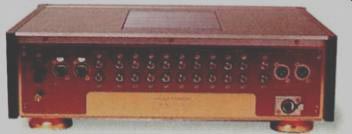
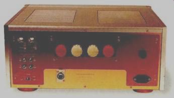
------The SM-5 amp has unusual speaker connectors.
The SM-5 amp has three selectable in puts, two unbalanced and one balanced, which could be useful for those with no preamp but several line-level signal sources.
Front-panel controls consist of two calibrated rotary input-level knobs, a rotary in put selector, and a pushbutton power switch. Rear-panel facilities include inputs, speaker connectors, a normal/bridged mode slide switch, a connector for the BB-5 power supply, an IEC AC-cord socket, and an AC line fuse. I was impressed with the speaker connectors, which use large knobs to control thick, movable plates that clamp wire or spade lugs inserted into top openings on the connector assembly. Much to my amazement, they would accept and hold the thick, angled spade lugs on my Cardas speaker cables.
Marantz says the BB-5 can power one SC-5 and one SM-5 in stereo mode for about 7 to 8 hours. With two SM-5s going, the operating time on batteries decreases to about 5 to 7 hours. A front-panel meter shows the DC voltage available. Three front-panel pushbuttons allow selection of battery charge, AC operation while charging, or DC operation from the batteries.
All three components appear to be constructed of aluminum. The internal side pieces, front subpanels, rear panels, and bottom (but not top) covers are copper-plated. In the SC-5 preamplifier, a copper-plated subchassis is bolted to the side pieces; the main audio p.c. board is mounted to this subchassis with standoffs. A thick piece of felt covers the top surface of the subchassis, presumably to damp mechanical vibrations. The in side surfaces of the SC-5's side dress panels are similarly lined with felt.
On the main audio board, copper shields separate the phono section, the two out put sections, and the area where balanced input signals are converted to the unbalanced form used by the subsequent circuitry. Each functional area has two of the potted HDAM gain blocks 2 plus a handful of such external parts as discrete transistors, ICs for servo functions, resistors, and capacitors. The phono section has two larger potted modules that presumably contain the moving-coil circuitry. Signals are carried to and from the main audio board by shielded cables. The main volume control is a beautiful, machined cylindrical piece, an Alps unit I haven't seen in any other equipment.
The BB-5 also has a subchassis, upon which all its components are mounted. The two batteries are nominal 12-volt types, rated at 3.4 ampere-hours apiece.
The SM-5 power amplifier contains two large heat sinks and a potted toroidal transformer, among other components. An internal shield separates the left-channel heat sink from the input amplifier module and from the signal input jacks on the rear panel.
In general, parts and build quality of these Marantz components are typical of high-grade Japanese equipment--excellent but not quite up to the standards of elegance and perfection that I have encountered in the best American high-end gear.
As in most other preamplifiers with balanced and unbalanced inputs and out puts, the SC-5 converts balanced input signals to unbalanced ahead of the main signal selector and volume control. Relays are used for signal switching. The selected input signal passes to the main volume control, which (regardless of Marantz's claim) is a conventional passive potentiometer. There are, however, active level controls in the SC-5: the level-trim controls that are used instead of a balance control. The attenuation resistors in these controls are actually shunt feedback resistors for the output amplifiers, which are fed directly from the preamplifier's volume control. Each output amp uses two HDAMs per channel, with a servo circuit to keep DC offset close to zero.
The HDAMs themselves apparently consist of a differential front end followed by a complementary gain stage that, in itself, can't drive much of a load. Every HDAM in the SC-5 is therefore followed by a two-stage complementary emitter-follower out put buffer that is included in the particular circuit's negative feedback loop. In the phono preamplifier block, each HDAM is preceded by a discrete input stage. An RIAA-equalization feedback loop encloses the whole circuit. Switching between MM and MC gain modes is accomplished by changing the shunt feedback resistor.
In the SM-5 power amplifier, the selected input passes to the 1-dB/step input-level attenuators. The relay switching network that selects stereo or bridged mode feeds four HDAMs, two per channel, connected as unity-gain noninverting buffers. Another HDAM is the input stage for what I would term the power amplifier proper. This is followed by an unusual arrangement of a complementary J-FET source-follower stage driving a complementary bipolar common-base stage, which in turn feeds a complementary cascode voltage amplifier.
The output stage is a triple Darlington emitter-follower with four output transistors per channel.
Measurements
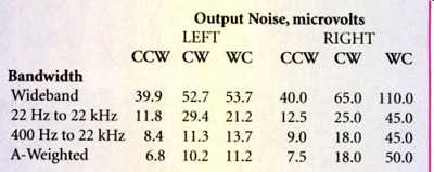
Table I--Output noise levels for SC-5 preamp's line section, with unbalanced
input and output. Volume-control settings shown are full counterclockwise (CCW),
full clockwise (CW), and worst-case (WC, which was typically at-6 dB). Unbalanced
inputs were terminated with 1 kilohm, and balanced inputs were terminated with
600 ohms per phase.

Table II--Output noise levels of SM-5 amplifiers.
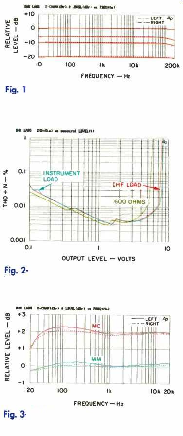
Fig. 1-Frequency response of SC-5 preamp vs. volume setting.
Fig. 2-THD + N vs. output level, SC-5 preamp.
Fig. 3-RIAA equalization error.
All of the following measurements were made with the BB-5 in AC-power mode.
Using the battery-power mode made no difference in any of the tests. The majority of the measurements for the SC-5's line output section are for unbalanced input and output. If a characteristic was noticeably different in the balanced mode, it is noted.
Gain and sensitivity measurements for the SC-5 were essentially equal in both channels. Line-amp gain from the unbalanced input was 20 dB at the unbalanced output, nearly 7 dB higher at the balanced output, and-0.5 dB at the tape output; with balanced input, gain was about 1.5 dB lower in each case. Phono gain for MM input averaged 55.4 dB to the unbalanced output, 61.4 dB to the balanced output, and about 34.6 dB to the tape output; MC gain was just about 22.2 dB higher for all outputs.
Line-section sensitivity for unbalanced input was 49.7 millivolts at the unbalanced output, 25 mV at the balanced output, and about 532 mV at the tape output. For balanced inputs, the results were about 60, 30, and 648 mV, respectively. Phono sensitivity with unbalanced output was about 850 microvolts for the MM input and 66 µV for the MC input, while sensitivity with the balanced output required just about half those figures. Phono sensitivity at the tape outputs was about 9.3 mV for MM and 727 µV for MC.
Frequency response as a function of volume-control attenuation for both channels is shown in Fig. I. Clearly, the SC-5 is a wideband design. Further, a rough idea of the interchannel balance error can be gathered from the figure. At the -6 dB point, the volume-control circuit has its lowest high-frequency cut off point. At lower settings, response flattens out again, as shown by the -20 dB curve. Response remained constant at lower settings (not shown) and at various level-trim settings. Interchannel balance error was within 0.5 dB down to 96 dB of attenuation, and actual attenuation was within 4 dB of the front-panel markings between -40 and -80 dB. With the volume control at maximum and gain trim at-6 dB, rise and fall times (with instrument loading at an output level of ±5 volts) were about 380 nsec, which corresponds to a-3 dB point (or an equivalent band width) of some 920 kHz. With an IHF load, the rise and fall times increased to 500 nsec, for a band width of 700 kHz. With the volume set to -6 dB, rise and fall times increased to about 1.4 µsec, for an equivalent bandwidth of some 250 kHz. This is, indeed, one fast circuit! The SC-5 did not invert signal polarity with unbalanced or balanced input and output. However, polarity was inverted for balanced input with unbalanced output (and vice versa).
Common-mode rejection of the balanced inputs (not shown) rose at about 6 dB/octave from a level of-60 dB at 10 Hz to a bit less than-10 dB from about 10 kHz up; this was a bit disappointing for what appears to be sophisticated circuitry. Both channels behaved identically.
Total harmonic distortion plus noise (THD + N) is plotted in Fig. 2 for unbalanced input and output of a 20-kHz signal. As can be seen, the IHF load slightly lowers the output level at the onset of clipping, and the 600-ohm load is driven at low distortion to above 5 volts rms. In the balanced input and output mode (not shown), maxi mum output was about 13 volts before clip ping, with instrument or IHF loading, and distortion reached a low of 0.001% to 0.002% for outputs of 5 to 10 volts. With a 600-ohm load (which is really 300 ohms per driving phase), maximum output was about the same level seen in the figure. The SC-5's distortion performance is quite good.
The preamp's interchannel crosstalk was down more than 80 dB from 20 Hz to 4 kHz; it rose at 6 dB/octave to about-67 dB at 20 kHz. High-frequency crosstalk was better in the balanced input and output mode, remaining more than 80 dB down at 20 kHz.
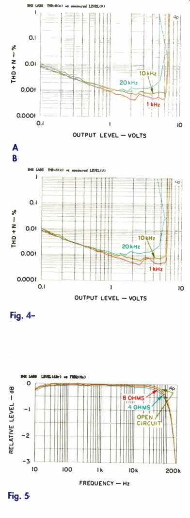
Fig. 4--THD + N vs. output level with instrument load (A) and IHF load (B),
MM phono section.
Fig. 5--Frequency response of SM-5 amp.
The SC-5's output noise as a function of bandwidth and volume-control position is listed in Table I for unbalanced in put and output. An intermittent sputtering noise in the right channel at the-6 dB volume setting prevented my getting all the noise data desired for that channel, so the left-channel data is more representative. I also measured IHF signal-to-noise ratio (S/N for 500 mV in and out) for all input and output conditions. I found the S/N at the unbalanced outputs was a bit lower when measured for unbalanced in put (95.5 dB for the left channel, 90 dB for the right) than for balanced input (97.7 and 94 dB, respectively). However, S/N at the balanced outputs remained constant for either type of input, measuring 93.0 dB in the left channel and 91.5 dB in the right.
The Marantz preamp's input impedance was 10.2 kilohms for balanced inputs, independent of volume setting. With the unbalanced inputs, the input impedance was 5.2 kilohms with the volume control down in the working range and 4.5 kilohms with the control fully up.
Output impedance was 100 ohms for the unbalanced outputs and 200 ohms for the balanced out puts. The DC offset, measured at pins 2 and 3 of each channel's XLR output jack, was a maximum of 1.4 mV.
RIAA equalization error of the SC-5's phono section is plotted in Fig. 3. Results are shown for instrument loading; IHF loading reduced the overall output level by some 0.8 dB and the high-frequency response at 20 kHz by about 0.07 dB.
Figures 4A and 4B show THD+N in the MM mode. The strange foldback in the 20-kHz curves is a real phenomenon. At frequencies near or above 20 kHz, the SC-5's phono circuit virtually paralyzes whenever a certain in put level is reached. While distortion is assuredly rising at this point, the circuit starts to clip, thereby reducing the output voltage. Luckily, this occurs at input levels no one is likely to en counter. When I attempted to measure phono overload versus frequency, the circuit's overload behavior prevented my getting data above about 5 kHz. At 1 kHz, however, input overload was an ample 125 mV. In the MC mode, the high-frequency input over load was better, enabling me to get data up to 10 kHz. Input over load at 1 kHz was about 15 mV for this mode.
Phono-circuit interchannel crosstalk, with the undriven channel's input terminated by a 1-kil ohm resistor, was better than -85 dB up to 1 kHz and rose at less than 6 dB/octave to-68 dB at 20 kHz. With the IHF simulated MM source, the crosstalk peaked at-45 dB at 10 kHz. With the MC input terminated with 100 ohms, crosstalk was better than-85 dB up to about 3 kHz and then rose at 6 dB/octave to-68 dB at 20 kHz. For both the MM and MC inputs, crosstalk behavior was very similar in the left-to-right and right-to-left directions. Phono S/N for either channel was 72.7 dB in MC mode and 72.5 dB in MM mode.
For the SM-5 power amplifiers, most of the data presented here is from a single amp. The four channels in the two amplifiers performed very similarly in the vast majority of my tests.
Amplifier gain measured a little over 26 dB, and input sensitivity was just about 137 mV. These results are for either channel and for both balanced and unbalanced input.
For bridged operation, gain was approximately 32 dB, and sensitivity was 68.7 mV.
Frequency response at 1 watt/channel, in stereo mode and with unbalanced input, is plotted in Fig. 5. (Response was very similar for unbalanced input in the stereo mode and for unbalanced and balanced inputs in the bridged mode.) As can be seen, the -3 dB point (bandwidth limit) is close to 200 kHz. Rise and fall times at an output level of ±5 volts into 8 ohms were 1.8 µsec at the normal (full clockwise) setting of the input level controls. With the amplifier's input level controls set 6 dB below maximum, rise and fall times increased to 2.2 u-sec, and bandwidth was reduced to about 160 kHz.
Square-wave measurements (not shown) revealed a slight overshoot at an output level of ±5 volts into 8 ohms. This overshoot, which is unusual in a modern solid-state power amp, was present in all four channels of the two SM-5s. When a 2-pF capacitor was paralleled across the 8-ohm load, the resultant ringing was minimal and well damped. Some amount of tilt could be seen in the 40-Hz square wave.
Figure 6 shows THD + N and intermodulation distortion versus power output in bridged mode. (The curves for the stereo mode were similar but with lower power levels.) The fact that the power level at clip ping does not come close to doubling as load impedance is halved demonstrates the relatively loose regulation of the SM-5's power supply. This amp will have good dynamic headroom, as we shall see. A graph of bridged-mode THD + N versus frequency, for various power levels into 4 ohms (Fig. 7), shows admirably little increase in distortion at high frequencies.
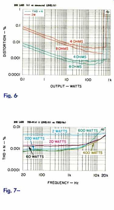
Fig. 6-THD + N and SMPTE-IM distortion vs. power, SM-5 amp.
Fig. 7-THD + N vs. frequency, bridged mode, SM-5 amp.
The SM-S's output noise levels, for stereo operation with unbalanced input, are listed in Table II. The results are outstandingly low. The IHF S/N ratio for the same conditions was 99.9 dB. It dropped imperceptibly, to about 99.75 dB, with balanced input; for bridged operation, S/N was 96.4 dB with unbalanced input and 96.2 dB with balanced input.
Damping factor was 277 for the left channel and 261 for the right channel up to about 800 Hz. It then fell to about 68 at 20 kHz. In the bridged mode, the damping factor was about 165 up to about 800 Hz again; it fell to about 40 at 20 kHz.
In the test of dynamic power, the SM-5 amp could deliver 175 watts/channel into 8 ohms at the beginning of the IHF tone burst signal and 163 watts/channel at its end. With 4-ohm loads, the results were 325 and 264 watts/channel, respectively. Corresponding figures for dynamic headroom were 2.4 dB for 8-ohm loads and 2.1 dB for 4-ohm loads. In bridged mode, power into 8 ohms was 676 watts at the start of the burst and 576 watts at its end; with a 4-ohm load, those figures were 1,104 and 800 watts, respectively. Corresponding dynamic headroom for 8-ohm loading was 2.3 dB. Steady-state power at the visual onset of clipping in stereo mode was 147 watts/channel into 8 ohms and 245 watts/channel into 4 ohms. In bridged mode, clipping power was 503 watts into 8 ohms, 732 watts into 4 ohms, and 866 watts into 2 ohms. Driving one channel into a 1-ohm load yielded ±38 volts, for a peak current of ±38 amperes.
Input impedance was 11 kilohms for unbalanced mode and 21.5 kilohms for balanced mode.
Output DC offset for one SC-5 was 0 mV for the left channel and-0.7 mV for the right. For the other amp, it measured +3.6 and-3.2 mV, respectively.
The AC line draw when the SM-5 was first powered up on a fairly cold morning was about 440 mA; it stabilized at about 600 mA when the amplifier warmed up. When the amp was really heated up, line current remained essentially unchanged, which indicates excellent output-stage thermal stability.
Use and Listening Tests
Phono equipment in my system during the review period included an Oracle turntable, a Well Tempered Arm, and Stanton's 981 HZS moving-magnet cartridge used with my own preamp (a tube phono stage with a passive signal selector and volume control) or a Quicksilver Audio preamp. For CDs, a Counterpoint DA-11A transport drove Museatex Bidat, Sonic Frontiers SFD-2 MKII, and other (experimental) D/A converters. Additional signal sources included a Nakamichi ST-7 FM tuner, a Nakamichi 250 cassette recorder, and a Technics open-reel recorder. In addition to the preamplifiers mentioned above, I used a Forssell tube balanced line driver and a First Sound II passive model. Power amplifiers used for comparison were a Crown Macro Reference, a pair of Quicksilver Audio M 135s, and an Arnoux 7B digital switching design. My loudspeakers were B & W 801 Matrix Series 3s, augmented from 20 to 50 Hz by my two subwoofer systems, each of which has a JBL 1400Nd driver in a 5-cubic-foot ported enclosure.
For my initial listening tests, I set up one Marantz SM-5 power amplifier in stereo mode but did not use the companion SC-5 preamp. The amplifier sounded quite good but was slightly closed in and darker tonally than the Arnoux switching amp I had been using. I then tried the Crown Macro Reference and thought that the Crown sounded a bit clearer and more spacious than the Marantz amp. I was impressed with how close these two amplifiers sounded, however.
I next listened to the same Marantz SM-5 with the SC-5 preamplifier and with the Forssell line driver, to assess the sonic characteristic of the SC-5. The Marantz preamp seemed to soften the sound and reduce spaciousness, a sin of omission that made the music enjoyable and easier to listen to but took away some of its vitality, drive, and space.
After I completed the measurements, I set up both SM-5s in bridged mode along with the BB-5 power supply and SC-5 pre amp for my final listening session. Whoa! In the bridged mode, these amps do kick butt! Bass impact was great, and the over all sound of the combination was musically lush and smooth.
It was, however, still a little lacking in resolution and spaciousness compared with my reference setup. I think that the SM-5 amplifiers are more neutral than the SC-5 preamplifier.
I was surprised run on battery power when the BB-5's AC cord was disconnected. This could be a mild disappointment for those tweaks (including me) who suspect the sound might be better with no physical connection to the AC line.
The Marantz equipment was very pleasurable and sensuous to use, and the volume control on the preamp felt especially wonderful. In conclusion, I think that Marantz has created some impressive top-of-the-line components.
(Audio magazine, Jan. 1996)
Also see:
Marantz Model 4400 Stereo/4-Channel Receiver (Equip. Profile, Sept. 1974)
Marantz Model 2500 Stereo FM/AM Receiver (Equip. Profile, Feb. 1978)
Marantz Model Nineteen FM Stereophonic Receiver (Equip. Profile, Mar. 1971)
Marantz Model 250 Stereo Power Amplifier (Jun. 1972)
Marantz Model 22 AM/FM Receiver (Apr. 1970)
Marantz Model 1150D Stereo Control Amplifier (Mar. 1976)
Marantz PM-94 Integrated Amplifier (Dec. 1988)
Link |
Marantz Model 50308 Stereo Cassette Deck (Dec. 1978)
= = = =