MANUFACTURER'S SPECIFICATIONS
IHF Usable Sensitivity: Mono, 1.6 µV; stereo, 3.0 µV.
50-dB Quieting: Mono, 3.0 'Al; stereo, 30 V.
THD: Mono, 0.15%; stereo, 0.20%.
S/N: Mono, 70 dB.
Capture Ratio: 1.5 dB.
AM Suppression: 100 dB.
Image Rejection: 100 dB.
Alternate Channel Selectivity: 120 dB.
Spurious Rejection: 100 dB.
Frequency Response: 20 Hz to 15 kHz ±0.5 dB.
Stereo Separation: 1 kHz, 45 dB; 10 kHz, 35 dB.
Drift: 15 kHz.
Rated Output Voltage: 1.0 V rms.
General Specifications:
Power Requirements: 110.125 V 50/60 Hz, 25 watts.
Dimensions: 17 in. W x 5 1/2. in. H x 10 1 in. D.
Weight: 23 lbs.
Price: $650.00.
The term "digital" as applied to an FM tuner may mean one of two things. Either the tuner employs crystal-controlled operation of a frequency-synthesis scheme, which insures absolute tuning accuracy and which readily lends itself to digital display of tuned frequencies, or the tuner employs conventional continuously variable tuning and has added digital "counting circuitry" and displays to replace the conventional tuning dial pointer and printed frequency scale. The SAE Mark VIII tuner falls in the latter category, which means that additional money is being spent on those attractive numeric readouts and associated circuits, and if LED readouts were all the SAE tuner had to commend it, we would have had to think twice about extolling its virtues.
However, this particular "digital readout tuner" is such an excellent one in so many other respects that it is possible to overlook the extra cost on the premise that even without this digital display, the Mark 8 tuner would still be worth its price.
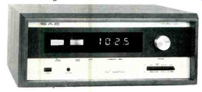
The front panel of the tuner has a long blacked-out section which becomes illuminated with giant numerals and a pair of meters when power is applied. Numbers change in increments of 0.2 MHz, and we were able to tune down to 87.5 and up to 108.5 MHz by turning the large tuning knob which is flywheel-coupled and behaves for all the world just like any other FM tuning knob. Four pushbuttons at the lower left turn on power, select one of two muting threshold levels, activate the muting circuit, and select one of two output levels which are set 10 dB apart. A symmetrically positioned array of four more pushbuttons at the lower right activate a stereo noise filter, change de-emphasis from 75 microseconds to 25 microseconds, switch from mono to stereo, and select stereo-only reception. At the lower center of the panel is a tape-out jack (of the two-circuit variety similar to a headphone jack) to which a tape deck can be connected for recording purposes. High-impedance phones may also be connected at this point for direct listening to the tuner, bypassing the need for an amplifier. Between the signal-strength and center-of-channel tuning meters and the digital display areas is a stereo indicator light.
The rear panel of the SAE Mark VIII contains a pair of output jacks, vertical and horizontal 'scope jacks (for 'scope observation of multipath), a four-channel (detector) output jack, and a barrier-type terminal strip for connection of other 75-ohm or 300-ohm antenna transmission lines. A fuse holder containing a half-ampere line fuse is also accessible from the rear panel.
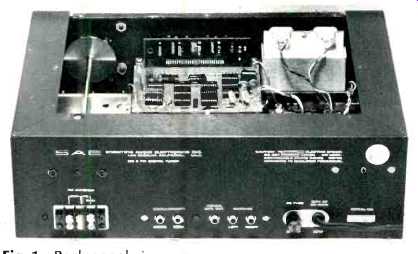
Fig. 1-Back panel view.
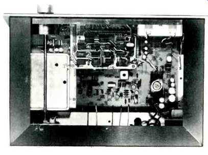
Fig. 2-Interior view.
Circuit Description
Aside from the sealed front-end, the internal layout of the chassis contains two major circuit boards, both of glass-epoxy material. (See Fig. 2). The lower p.c. board contains i.f. and MPX circuitry, while the upper board contains the necessary IC logic circuits to activate the digital display. A block diagram of the tuner is shown in Fig. 3. A 5-ganged, capacitor-tuned front-end uses 3 MOS-FETs, two of which are used in a cascode-type r.f. amplifier. Five double-pole, monolithic, fixed tuned-resonance, pass-band filters are used in the i.f. section, coupled with seven symmetrically limiting differential-amplifier, IC limiter stages followed by a wideband ratio detector. Five of these limiter amplifiers have their output coupled to amplitude detectors which are connected to a summing amplifier to activate the logarithmically calibrated signal-strength meter.
A phase-locked-loop IC is used for MPX detection, followed by separate 19-kHz and 38-kHz, double-tuned, lowpass filters. Complementary d.c.-coupled, feedback pair amplifiers are used in the audio amplification chain.
A 4-digit readout system is coupled to the local r.f. oscillator. Readout is indicated by four seven-segment displays, which use a total of 56 LEDs. Fourteen digital ICs referenced to a quartz crystal having 0.004% accuracy, are used in the divide-down and frequency-counter logic system.
Laboratory Measurements Noise and THD curves for mono and stereo operation of the Mark VIII tuner are plotted in Fig. 4. IHF Usable sensitivity in mono measured 1.8 µV, (10.5 dBf), while in stereo, 4.2 µV (17.9 dBf) of signal was required to achieve the same noise-plus-THD level of 3%. The 50-dB quieting mark in mono was achieved with a signal input of only 2.2 µV (12.2 dBf), about the lowest we have ever measured since this important new specification became a required disclosure. In stereo, 25 µV (33.35 dBf) was needed to achieve 50 dB of quieting-again, much better than average. Ultimate S/N in mono measured 75 dB, while in stereo the best signal-to-noise reading was 73 dB, remarkably low compared with even higher priced tuners we have measured.
Harmonic distortion in mono was 0.13% at mid-frequencies; 0.15% in stereo. At the more difficult test frequencies of 100 Hz and 6 kHz, THD was 0.19% for both mono and stereo operating modes at 100 Hz, and 0.11% and 0.35% for the 6-kHz tests. Distortion versus frequency for the entire FM audio band is plotted along with stereo FM separation characteristics in Fig. 5.
Rejection ratios (image, i.f., and spurious) were all better than 100 dB-the limit of our test equipment. Capture ratio measured 1.4 dB, and AM suppression was an outstanding 97 dB, though some degree of error may have been introduced when trying to measure such high suppression ratios. Alternate-channel selectivity was outstanding and well above 110 dB (again, our limit of measurement). Stereo separation was outstanding, with readings above 50 dB obtained for mid frequencies and 36 dB at 10 kHz. The two muting threshold levels were set at the factory for 3µV (14.9 dBf) and 13.0 µV (27.7 dBf), while stereo switching took place at 4 µV, by which time S/N was already 35 dB below full output and THD was precisely at the 3% point deemed least usable.
The 19-kHz and 38-kHz sub-carrier products at the output were filtered out to a level of-65 dB with respect to full modulation. What's more, this effective filtering is accomplished without significant alteration of frequency response, which remains true to the appropriate de-emphasis curve selected within 0.3 dB from 30 Hz to 15 kHz. That's really good low-pass filter design!
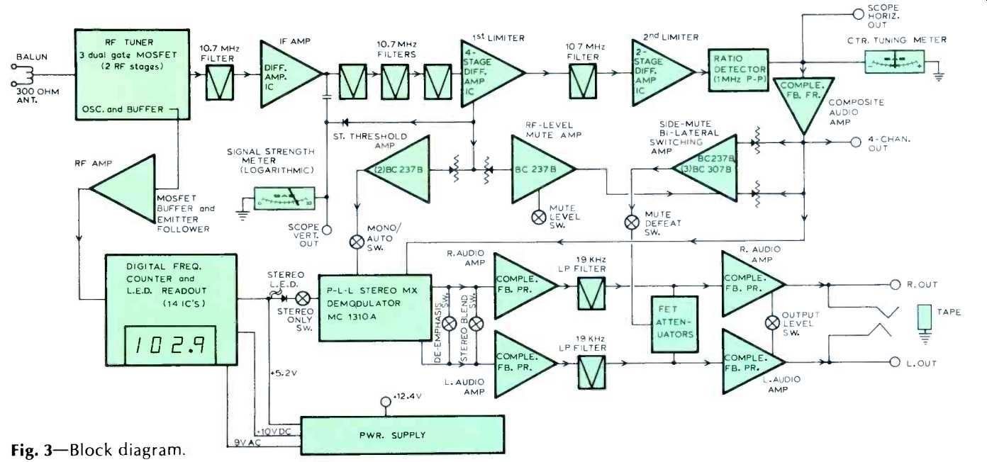
Fig. 3-Block diagram.
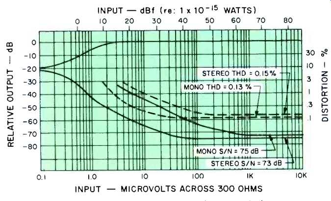
Fig. 4-FM quieting and distortion characteristics.
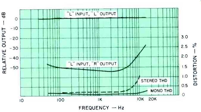
Fig. 5-Separation and distortion versus frequency.
Use and Listening Tests
It goes almost without saying that any tuner having such superb measured performance will be limited in practical use by the quality of signals broadcast in your area. Unfortunately, in the metropolitan New York area, where we perform our laboratory measurements and listening tests, there are but one or two really good FM signals, and even those don't measure up to the ability of this tuner to reproduce clean, quiet signals. We have learned that one station is about to undergo what amounts to a transmitter overhaul in an attempt to bring its broadcast signal quality up to that of some of the state-of-the-art tuners available. SAE's Mark VIII certainly is a tuner we will be most anxious to hear again when that station's signal has been refined-especially since the man who has been charged with the task is none other than Richard Sequerra, whose latest tuner design abilities are familiar to readers who follow Audio's test reports.
The only negative note I can sound is a personal expression that I find the giant digital readout somewhat splashy despite its high visibility from across the room. However, I have to admit that many people, if not the majority of potential buyers, will find the display attractive. Since the performance would have been exactly the same if a conventional dial pointer and frequency scale had been used instead of the digital display, I wonder how much lower the price would have been without the display. And whether those who could then afford and would purchase the tuner wouldn't offset the number who were purchasing it simply because of the digital display. All this is, of course, idle speculation since taste is a rather unpredictable item.
-Leonard Feldman
(Audio magazine, 1976)
Also see:
SAE MARK SEVEN STEREO OCTAVE EQUALIZER (mar. 1971)
SAE A202 Amplifier (Jul. 1987)
SAE Model 2922 Integrated Amplifier (Mar. 1979)
SAE Mk XII Speaker System (May 1973)
SAE Model 5000 Impulse Noise Reduction System (June 1977)
= = = =