----------
by D. B. KEELE, JR.
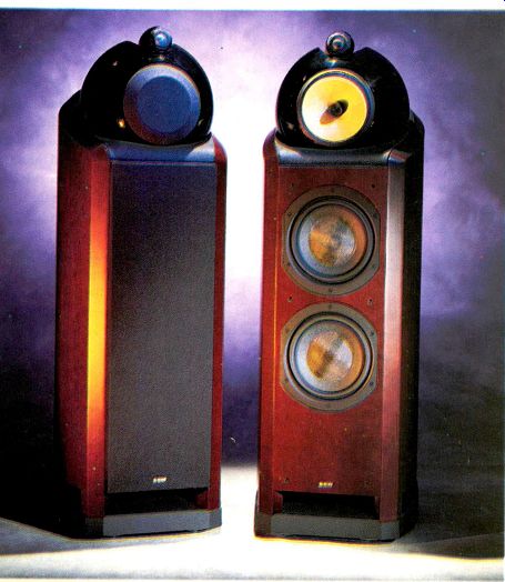
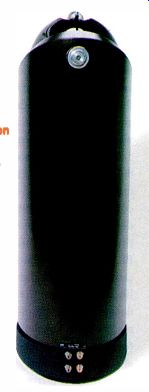
B&W NAUTILUS 802 SPEAKER
Rated Frequency Response: 39 Hz to 20 kHz, ±2 dB; -3 dB at 34 Hz and 22 kHz, -6 dB at 27 Hz and 30 kHz.
Rated Sensitivity: 91 dB at 1 meter, 2.83 V rms applied.
Rated Impedance: 8 ohms, nominal; 3 ohms, minimum.
Recommended Amplifier Power: 50 to 500 watts.
Dimensions: 43.5 in. H x 15.2 in. W x 21.6 in. D (110.6 cm x 38.5 cm x 54.8 cm).
Weight: 154 lbs. (70 kg) each.
Price: $8,000 per pair; available in black ash, natural cherry, and red -stained cherry real -wood veneers.
Company Address: 54 Concord St., North Reading, Mass. 01864-2699;
978/664-2870; www.bwspeakers.com.
The English speaker manufacturer B&W has the unusual distinction of enjoying high regard in both the audiophile and professional sound communities-something many companies aspire to but very few achieve. B&W's professional reputation is based on wide use of its products as studio monitoring speakers for classical music recording. The accuracy of these speakers, their smooth response, excellent imaging, even coverage, and reliability suit home users as well as pros, however.
The largest and most expensive system in B&W's previous line, the 801 Matrix Series 3, was also the most highly revered (I re viewed the Series 2 for the November 1990 issue of Audio). Several of this magazine's reviewers (including me) use the 801 Series 3 as a reference loudspeaker.
The Nautilus 800 Series, which had been brewing for more than five years, is a major update of B&W's 800 line. The new line is based on technology developed in the de sign of the company's avant-garde Nautilus loudspeaker in the mid -1990s (not quite reasonably priced, at $40,000 per pair!).
The Nautilus, whose appearance resembles that of an extremely large spiral conch or snail shell with three rearward -pointing, racy-looking tapered structures on its top, is B&W's attempt at making the world's most accurate loudspeaker.
The new 800 Series consists of seven models, designed for both stereo and home theater use, ranging in price from $11,000 per pair for the Nautilus 801 down to $1,000 each for the Nautilus HTM2 center-channel speaker. The new systems are deliberately designed to appeal to both professional and home users. Whereas the original 800 Series speakers were primarily pro systems and had a typically no-non sense, utilitarian look, the styling and industrial design of the new Nautilus 800 models are top-notch by any standard.
Technically, a primary goal of the new series was greater dynamic capability: higher sensitivity, more headroom, and the ability to play louder than the equivalent models in the preceding line.
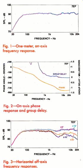
Fig. 1-One-meter, on -axis frequency response.
Fig. 2-On-axis phase response and group delay.
Fig. 3-Horizontal off -axis frequency responses.
The Nautilus 802 is one step down from the top, at $8,000 per pair (about twice the price of the 802 Series 3 it replaces). The Nautilus 801 and 802 are both three-way designs and use exactly the same midrange and tweeter assembly. The squat, imposing Nautilus 801 is superficially similar to earlier 801 models but has a 15 -inch woofer in place of the 12 -inch driver used previously.
The Nautilus 802 also maintains the basic traditions of its model designation, with a columnar woofer enclosure that is significantly narrower and shallower than the 801's. And in place of the 80l's single large woofer is a vertical array of two 8 -inch drivers. B&W says the crossovers are at 350 Hz between the woofers and midrange and at 4 kHz between midrange and tweeter.
Despite the similarities to earlier 802s, the Nautilus 802 has a very distinctive look that stems from its Nautilus pedigree. Some of the differences are not obvious, however.
For example, the bottom portion of the cabinet, which forms the enclosure for the dual woofers, appears to be fairly conventional. Yet its curved sides and back and its massive internal matrix stiffening are any thing but ordinary. The curved panels re duce diffraction and are inherently stiffer than flat panels of the same thickness. The 802's long -throw woofers have die-cast aluminum chassis and rigid cones made of a Kevlar and paper pulp composite. The dust-cap is formed of carbon fiber.
The woofers face forward in the usual way, but the enclosure has a somewhat unconventional port on its bottom that radiates through tapered slots on three sides of the cabinet. The port itself is strongly flared both inside and out and has dimples on its surface, which is said to smooth airflow and reduce bass chuffing sounds.
The base of the cabinet is a heavy-duty cast -aluminum assembly that stabilizes the enclosure and houses the crossover. On its bottom are four ball -bearing roller glides that assist in maneuvering the system (handy, given that the speaker weighs a very heavy 154 pounds). Spikes, for use when you've determined the 802's final operating location, are also provided. These are not the usual pointed, headless bolts but 1 3/4 -inch diameter x 1 1/2 -inch high cones composed of machined-aluminum, flanged bases with removable, stainless -steel points.
Each spike assembly attaches to the bottom of the base with four bolts.
The Nautilus 802's most strikingly distinctive feature is its mid range/tweeter assembly. The 6 -
inch midrange driver is housed in a shiny, very rigid, sphere -shaped enclosure with a tapered tail that extends to the rear.
The tweeter is housed in its own tapered assembly, attached to the top of the midrange enclosure.
The midrange driver, which B&W calls a Fixed Suspension Transducer (F.S.T.), has a woven Kevlar diaphragm with a "surround-less" suspension and a die-cast aluminum basket. Eliminating the traditional surround is said to remove the single major cause of midrange anomalies, "the surround resonance," in which the surround vibrates opposite to the cone, causing peaks and dips in the frequency response. The midrange's surround is actually a 1/8 -inch -thick ring of foam that is said to optimally match the traveling -wave impedance of bending waves in the cone and thus minimize reflections from the cone's outside edge. The resultant driver has less excursion capability than one with a normal surround, but B&W says that the driver's operating range makes greater excursion unnecessary.
The diaphragm has no dustcap, instead vibrating around a central, stationary, bullet-shaped cone that is said to improve off-axis response.
B&W calls the midrange enclosure's long tail a reverse horn. It, together with the housing's shape, is said to greatly reduce internal reflections and to provide a smooth, diffraction -free outside surface that improves off -axis response. The enclosure is made of a synthetic resin material called Marlan and is filled with wadding.
The 1-inch aluminum-dome tweeter has a small, high -efficiency, neodymium-iron-boron magnet and an edge -wound, copper-coated aluminum ribbon voice coil cooled with magnetic fluid. The rear of the diaphragm faces through its backplate to a long, wadding -filled, tapered aluminum tube that is said to completely absorb the driver's back energy and also to act as a heat sink. The tweeter and tube are housed in a hard, cylindrical, die-cast shell that minimizes diffraction. The tweeter assembly attaches to a shaped depression in the top of the midrange enclosure.
The tweeter and midrange assemblies are acoustically decoupled both from each other and from the bass enclosure. This vibration isolation minimizes cabinet resonances and driver interactions. The vibration isolation is accomplished with gaskets made of a special gel -based, thermoplastic rubber material called IsoPath.
The Nautilus 802's crossover is on three separate printed -circuit boards, which is said to reduce electromagnetic interactions between the filters. Very -high -quality parts are used throughout, including heat-sinked thin-film resistors, polypropylene capacitor bypasses for the electrolytics, and all air-core inductors.
The woofers are driven through a third-order (18-dB/octave) low-pass filter, the midrange driver through a second-order (12-dB/octave) high-pass in cascade with a first-order (6-dB/octave) low-pass filter, with a resistor-capacitor impedance compensation circuit in parallel. The tweeter is fed by a third-order high-pass filter.
Connections to the Nautilus 802 are through bi-wirable terminal posts (five-way WBTs) on the bottom rear of the speaker.
The posts are made of gold-plated brass and accept banana plugs, spade lugs, bare wires, and WBT's side-entry copper pins.
B&W supplies short jumper cables to en able single wiring.
Separate grilles cover the woofers, mid range, and tweeter. The system can be operated without the woofer and midrange grilles, but B&W suggests leaving the tweeter EVERY DETAIL OF THE NAUTILUS 802'S CONSTRUCTION AND CABINETRY IS ABSOLUTELY THE BEST.
grille on to protect the tweeter's diaphragm.
B&W supplies a decorative midrange cone for use when its grille is removed.
Measurements The Nautilus 802's on -axis anechoic frequency response is shown in Fig. 1 with the woofer grille off and the midrange grille on.
Removal or replacement of these grilles made essentially no difference in the response, so no curves are shown for the alternative conditions. I made no tests with the tweeter grille off, in deference to the manufacturer's recommendation. Measurements were taken 2 meters away from the front of the cabinet, at a point halfway between the midrange and tweeter. I made ground -plane measurements below 250 Hz and used a large anechoic chamber for higher frequencies.
The curve in Fig. 1 is very flat overall and fits a very tight, 2.6 -dB, window from 62 Hz to 20 kHz. The response irregularities above 1 kHz are only very minor, with a slight depression at 2.2 kHz and slight peaks at 3.8 and 12 kHz. Relative to the level at 100 Hz, bass response is down 3 dB at 50 Hz, 6 dB at 39 Hz, and 9 dB at 32 Hz.
Above 20 kHz (not shown), lao there was a sharp, high-Q response peak of about 10 dB at 24.7 kHz.
(This corresponds to the first resonance of the tweeter's dome.) At higher frequencies, the response fell rapidly, passing through -3 dB at 30 kHz.
I measured the individual responses of the speaker's low- and upper -frequency outputs via its bi wire connections. The individual driver responses rolled off at 18 dB/octave above and below the 350 -Hz crossover. With both sections reconnected and in reverse polarity, the response did not exhibit much change as compared to the correct polarity connection-only a slight depression of about 2 dB at crossover. This indicates that the driver's acoustic outputs are neither in phase nor completely out of phase but are closer to 90° out of phase through the crossover region, a condition that maximizes lobing error. Ideally, the driver's acoustic outputs should be solidly in phase when connected normally and out of phase when connected in reverse (resulting in a deep null at crossover), to ensure that the speaker's directional lobe faces straight ahead through the cross over frequency range.
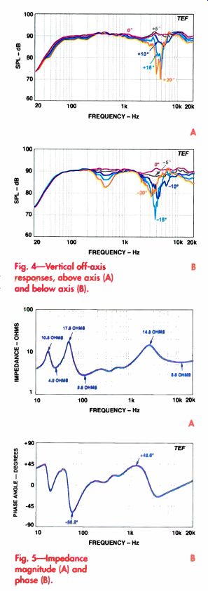
Fig. 4-Vertical off -axis responses, above axis (A) and below axis (B).
Fig. 5-Impedance magnitude (A) and phase (B).
Figure 2 reveals no surprises in the phase and group -delay responses. The Nautilus 802 is not time -corrected, but the midrange's acoustic output lags the tweeter's by only about 0.15 millisecond (as judged by the average group delay between 1.5 and 4.5 kHz). The phase, referenced to the tweeter's arrival time, exhibits no irregularities and is typical of most other direct -radiator systems. The wave form phase (not shown) indicated that waveshapes would not be pre served in any frequency range of operation, which is typical of loudspeakers not de signed specifically to maintain them.
Figures 3 and 4 show the Nautilus 802's off -axis horizontal and vertical frequency responses. You might be wondering where my usual "3D" off -axis curves are. Because
of the Nautilus 802's irregular shape and its heaviness, I was not able to run my usual vertical off -axis curves, which would have required rotating the speaker around its head. The limited vertical off -axis curves presented here were taken by physically raising and lowering the microphone rather than moving the speaker. I chose to present the horizontal off -axis curves in the same manner.
The horizontal off -axis responses, in 15° intervals from 0° to 45°, are shown in Fig. 3. In the main (±15°) listening window, the response is very uniform, essentially the same as the on-axis response.
Farther off axis, output starts drop ping above 1 kHz, with a sharper reduction between 2 and 4 kHz and a rolloff above 10 kHz.
Figures 4A and 4B show the vertical off -axis curves in increments of 5° from 0° to 20°. The above -axis curves on the forward axis are shown in Fig. 4A, the below -axis curves in Fig. 4B. The curves in Fig. 4A reveal major irregularities in the midrange -to -tweeter crossover region between 2 and 7 kHz. Al though the 5° curve is quite similar to the on -axis response, the response gets progressively more irregular as the angle increases.
Similar effects can be seen in the below -axis curves (Fig. 4B), al though in this direction even the 5° response is significantly different from the on -axis response. Here, however, the maximum deviation occurs at 15° off axis, with the response improving at 20° down. For the most part, the above- and be low -axis curves are quite symmetrical through the upper crossover range, which indicates minimal lobing error.
Response from 300 to 600 Hz, in the region of the crossover between woofers and midrange, is a some what different story. There is a dip in the below -axis curves that be comes deeper as the angle decreases. Because this dip is not much evident in the above -axis curves, strong lobing error is indicated. Fortunately, the response in this range is much more uniform for positions above the axis than below it.
Averaged from 250 Hz to 4 kHz (giving equal emphasis to each third -octave frequency band), the Nautilus 802's sensitivity measured 90.4 dB, very close to B&W's rating of 91 dB. The speaker's impedance magnitude, seen in Fig. 5A, exhibits a very low minimum of 2.8 ohms at 100 Hz. Maxi mum impedance is 17.3 ohms at 48 Hz. The dip at 25 Hz between the two low -frequency peaks, characteristic of a vented enclosure, indicates the tuning frequency. Above 1 kHz, the impedance rises to a broad peak of 14.3 ohms.
Figure 5B shows the impedance phase versus frequency, with a maximum of about +43° (inductive) at 1.3 kHz and minimum of about -58° (capacitive) at 59 Hz. At infrasonic frequencies, the impedance phase rises to +45° at 15 Hz.
The low impedance in the upper bass and lower midrange between 70 and 435 Hz, where it stays below 4 ohms, makes the Nautilus 802 a fairly demanding load for an amplifier. The impedance stays below 5 ohms over a wider range of 65 to 900 Hz.
B&W probably should have given this speaker a 4 -ohm rating. Amplifiers used with the Nautilus 802 should have high current capability to elicit optimum performance from it.
The Nautilus 802's minimum impedance of 2.8 ohms, coupled with the high (6.2) ratio of the maximum to the minimum, make its response relatively sensitive to cable resistance. To keep cable -drop effects from causing response variations greater than 0.1 dB, cable series resistance should be limited to a maximum of about 39 milliohms. Use of 12 -gauge or larger cable typically would fulfill this requirement.
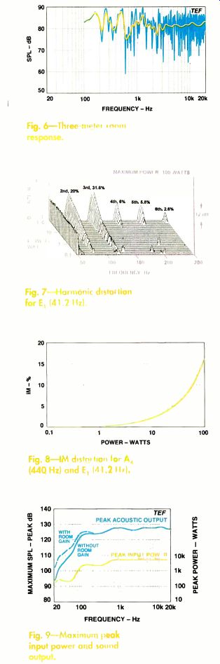
Figs. 6 - 9
When I drove the Nautilus 802 with a high-level sine -wave sweep, its cabinet was essentially inert, and there were no significant resonances. The only vibration of the woofers' enclosure was a slightly noticeable activity of the side walls at 365 Hz. I was unable to detect any vibrations of the mid range/tweeter assembly.
The Nautilus 802's woofers exhibited a generous excursion capability of about 3/4 inch, peak to peak. A sharp reduction in cone excursion occurred at 25 Hz, the vented-box tuning frequency. Port noise was very low when I drove the speaker to high levels at this frequency. Above the tuning frequency, the woofer reached maximum excursion at about 40 Hz, with an accompanying rise in distortion. (This happens to coincide with the 41.2 -Hz, E1, tone that I use to check low -frequency harmonic distortion.) The woofers exhibited no dynamic offset.
Figure 6 shows the Nautilus 802's 3-meter room response, with both raw and sixth-octave smoothed curves. The speaker was in the right-hand stereo position, aimed laterally at the test microphone, which was placed at ear height (36 inches) at the listener's position on the sofa. I drove the system with a 2.83 -volt swept sine wave. The direct sound plus 13 milliseconds of the room's reverberation are included. From 750 Hz and up, the smoothed curve fits a tight, 8.75 -dB, window. Above 2.5 kHz, it fits an even tighter window of 3.5 dB. Be low this frequency, the deviation increases somewhat, with peaks at 160, 260, and 500 Hz and only one significant, but not-too-deep, dip at 640 Hz. Overall, the curve fits a fairly tight, 12.6 -dB, window, including all peaks and dips.
Figure 7 shows the Nautilus 802's harmonic distortion for an E, (41.2 -Hz) input at power levels ranging from 0.1 to 100 watts (28.3 volts rms into 8 ohms), where THE SOUNDSTAGE WAS WIDE AND ROCK -STEADY, WITH WELL -CENTERED MONO IMAGES, the speaker generated a loud 104 dB SPL at 1 meter. Although the distortion rose to significantly high values of 20% second, 31.6% third, and 6% fourth and fifth, the Nautilus 802 sounded fairly clean because higher harmonics were quite low. The high second- and third -harmonic distortion was clearly audible, however. Why is the distortion so high? One reason is that the E, tone approximately coincides with the frequency of the woofers' maximum excursion within the passband-a consequence of the tuning of the vented enclosure.
The harmonic distortion for an A, (110 -Hz) input was quite low, less than 1.1% at all frequencies at full power. Distortion for an A4 (440 -Hz) input was also very low, consisting only of 1.35% second and third and with higher harmonics below 0.4%.
Figure 8 shows the 802's intermodulation distortion versus power for equal -amplitude tones of 440 Hz (A4) and 41.2 Hz (E1). The distortion rose smoothly, to a clearly audible 16.2% at full power. Most of the distortion was generated by the woofers, which were undergoing quite large excursions. Because the higher test tone (440 Hz) is just barely above the crossover between the woofers and midrange, the woofers contribute significantly to its reproduction. A lower crossover between them would have greatly reduced the IM distortion for this set of tones.
Figure 9 shows the Nautilus 802's short term peak -power input and output capabilities as a function of frequency, measured using a 6.5 -cycle, third -octave -bandwidth tone burst. I calculated the peak input power-by assuming that the measured peak voltage was applied across the speaker's rated 8 -ohm impedance.
The peak input power starts high, at 140 watts at 20 Hz; after reaching a peak of 280 watts at 26 Hz, it falls somewhat, to 205 watts at 45 Hz. The maximum input power then rises rapidly to 2.4 kilowatts at 125 Hz, falls slightly to 2.1 kilowatts at 300 Hz, and then rises to 5 kilowatts above 800 Hz. Note that if the system had been rated at 4 ohms, the upper -frequency power limit would have been 10 kilowatts! Between 125 and 630 Hz, the Nautilus 802's low impedance was a real challenge for my Crown Macro Reference amplifier, which ran out of current capability before the speaker reached its limit! With room gain, the peak acoustic output starts fairly high, at 102 dB SPL at 20 Hz, then rises quickly, passing through 110 dB at 30 Hz, 115 dB at 52 Hz, and 120 dB at 70 Hz. Above 100 Hz, the peak output varies in the very loud range of 124 to 128 dB SPL all the way up to 20 kHz.
-------p57 The Nautilus 802's curved back and sides lessen diffraction
and increase cabinet rigidity
Use and Listening Tests
What's the first thing I noticed about the B&W Nautilus 802s? In a word, weight.
From the four people it took to get them off the back of the truck to trying to get them down to my basement listening room, these babies were heavy! B&W suggests unpacking them in the same room where they will be used. Unfortunately, I couldn't do that.
The speakers had to be unpacked, then transported to the anechoic chamber for testing, and then loaded in my camper van and taken home to be set up in my listening room. I normally do most of my listening before doing any of the lab tests. In this case, I chose to do the chamber tests (frequency and polar responses) first because I knew it would be extremely difficult to get the 802s back upstairs once they were down in my basement for listening.
What's the second thing I noticed about the Nautilus 802s? Their appearance-very different and quite distinctive. The 802's styling elicited a very broad range of comments, not all of them good. The positive comments included "stunning," "wow," "cool," and "spectacular." Most of the negative comments came from those with no interest in high -end audio (including my wife) and ranged from "weird" to "ugly" to "what's that motorcycle helmet doing on top of the speaker?" The Nautilus 802s came with a raft of first-rate dealer support material that included a very well done installation/service video, a comprehensive service tool kit, and an excellent service manual with a complete set of detailed engineering drawings of all parts of this speaker. The service video turned out to be a godsend after I inadvertently burned out a tweeter during my tests and had to install a replacement. Because of the speaker's design, the procedure for driver replacement is not as straightforward as with most other systems.
Everything associated with the Nautilus 802s is top-drawer. Even the promotional literature is stunning! I also received a very comprehensive, half -inch -thick, 106 -page document titled "Development of the Nautilus 801 Loudspeaker" (available from B&W). This piece provided enough background material and illustrations on the design and development of the Nautilus 800 Series to fill sever al reviews! And every detail of the construction and cabinetry of the Nautilus 802 itself is absolutely the best.
Everything right down to the smallest particular is well thought out and extensively researched. B&W took no shortcuts.
Setup of the Nautilus 802s is a bit more involved than with more pedestrian loud speakers. At this price, buyers often have their dealers assist in or do the setups for them. The size and weight of these speakers does require at least two adults to facilitate unpacking and proper installation. The roller -glides on the bottom very much helped with positioning. The speakers are provided with a "transit fixing assembly" (B&W's words), in the form of a tube on the back, that secures the midrange/tweeter housing to the bass enclosure. This must be removed from the speaker before it is operated. Once the final locations of the speakers are determined, the optional spike assemblies can be attached. The owner's manual covers both the Nautilus 801 and 802. It goes into considerable detail about unpacking, connecting the speakers, placement, and other topics.
Now to the main point: How do these speakers sound? In a word, marvelous. They sound uncannily like the 801 Matrix Series 3s (well, maybe that's not too surprising) but with significantly greater maximum output and dynamic range capability, a smooth, noticeably brighter high end, and a tighter, cleaner low end. The port of the older 801s produces significant bass chuffing noises when driven hard by spectrally pure and concentrated bass tones. The Nautilus 802s did not have this problem. The 801s, however, could play slightly louder on material with content below 20 Hz.
I set up the 802s about 7 feet apart and canted in toward my listening position on the couch, about 8 feet away. Auxiliary re view equipment included an Onkyo DX-7711 CD player, a Krell KRC preamp, a Krell KSA-250 power amplifier, and Straight Wire cabling. I reduced the signal level fed to the Nautilus 802s by about 4 to 5 dB to match the lower sensitivity of the older 801s. (Such an increase in sensitivity is effectively equivalent to doubling or tripling the power of your amplifier.)
For this review, I dug out some CDs I hadn't listened to in a while. One special favorite is By Way of the World by Spies (Telarc CD -83305). This jazz CD, encoded in the now -defunct Shure HTS surround format (actually pretty much the same as Dolby Surround), is particularly dynamic and is a superb demo piece. The 802s performed spectacularly on it, particularly on my favorite cuts, tracks 6 and 7. Kick drum was loud and tight and did not exhibit any of the bass heaviness sometimes apparent from the old 801s. High percussion was especially effective and profited greatly from the 802's flatter high end; the laid-back character of the Matrix 801's treble came off second best. The beyond -the -speaker sound effects were fully evident, a testament to the Nautilus 802's imaging. Its soundstage was wide and rock -steady, with well -centered mono images.
On my favorite CD of my favorite symphony, Beethoven's Symphony No. 9 with Otmar Suitner conducting (Denon 38C37 7021; now available as Denon COZ 17001), the Nautilus 802s performed flawlessly in the difficult choral fourth movement.
The voices were commendably open and smooth, were free from any apparent mid range problems such as honking or straining, and could be distinctly separated from the accompanying orchestral sections.
Room sound and reverberation were reproduced in proper prospective.
I very much liked the Nautilus 802's performance on male speaking voice, especially since the older 801s have a tendency to add a bit of chestiness. Reproduction of female solo passages was quite smooth and unstrained.
On the stand-up/sit-down pink noise test, the 802s did not perform as well as the Matrix 801 Series 3s (which are nearly perfect in this test). Some upper -midrange tonal changes were evident when I stood up. The Nautilus 802's lateral listening window competed with those of the best speakers I have tested.
On low -frequency, third -octave, band-limited pink noise, the Nautilus 802s performed extremely well. At 20 Hz, the Nautilus 802 had slightly less clean fundamental output than the Matrix 801, but with essentially no port wind noise. At 25 Hz, however, performance favored the Nautilus 802s, again with very low port noise. At higher frequencies, the Nautilus 802's clean output equaled or exceeded the Matrix 801's. On all types of bass material, the Nautilus 802s excelled, delivering prodigious quantities of smooth, clean, extended output. They worked equally well on loud rock or pipe organ pedal notes.
The Nautilus 802's sensitivity is 4 or 5 dB higher than the older 801's, which really paid off on pop/rock, sound effects, and demo material with wide dynamic range.
This was particularly evident with the Krell amplifier (a mere 200 watts per channel into 8 ohms!), the amp that I did most of my listening with. The Nautilus 802s could play significantly louder and cleaner than the Matrix 801s. At the highest playback levels, the Matrix 801s were somewhat congested (presumably because of amplifier clipping) while the Nautilus 802s were quite clean. Lower -sensitivity systems, such as the Matrix 801s, profit greatly from higher-power amplifiers, such as the Crown Macro Reference (760 watts into 8 ohms) that I of ten listen with.
On a wide range of different types of program material, the B&W Nautilus 802s rose to the occasion and performed almost flawlessly. The Nautilus 802s are truly spectacular speaker systems, with world -class performance and appearance to match. If their $8,000 price is within your reach, and their somewhat out -of -the -ordinary look is to your liking, go for it!
-----------------
by EDWARD J. FOSTER
KENWOOD VR-2090 A/V RECEIVER
Rated Output, 6 -Ohm Loads: Stereo mode, 100 watts/channel, 20 Hz to 20 kHz, with 0.03% THD; surround modes, 100 watts/channel, at 1 kHz, with 0.07% THD. Dimensions: 17 3/6 in. W x 6.5 in. H x 15.5 in. D (44 cm x 16.2 cm x 39.1 cm). Weight: 26.4 lbs. (12 kg). Price: $999. Company Address: P.O. Box 22745, Long Beach, Cal. 90801; 800/536 9663.
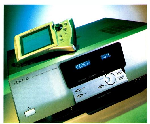
The centerpiece of Kenwood's current audio line is the VR-2090, a 100 watt/channel A/V receiver that offers Dolby Digital and DTS decoding, lots of inputs, a really nifty remote control, and good features for custom installation and dual-room/dual source operation.
But what grabs your attention first about the VR-2090 is its styling, which is so striking that you'd be hard pressed to miss it in a dealer's showroom. The front is brushed aluminum, with a tastefully sculpted central panel that is blessedly blank when the unit is off and, when on, displays legends that are large enough to see from across the room without binoculars. Because the characters are so big, only 15 of them can fit on the screen, so you may have to dodge down through submenus to get to what you want, but at least you can get everything from the front -panel display instead of from on screen menus. (What a blessing! I hate having to turn on a TV to listen to a CD!) Small legends at the left of the sculpted panel and three LEDs at its bottom augment the 15 -character main display. The legends illuminate when the VR-2090 is muted, when its tuner is locked to a station, and when a station is being received in stereo. The LEDs indicate the onset of clipping and the presence of Dolby Digital or DTS bit streams. The Kenwood uses separate 24 -bit Motorola 56009 DSP chips to decode those surround formats. A third Motorola chip, a 56007, handles bass management and such other DSP functions as generating ambience enhancement modes ("Arena," "Jazz Club," "Stadium," "Church," and "Theater").
The VR-2090 is operated best from its re mote control, but you can work it in a rudimentary fashion from the panel, using a volume control and five ellipsoidal buttons clustered below the display. The buttons are for speaker selection, muting, and round robin selection of inputs and display modes. An LED near each speaker switch lights when that set of speakers is selected. At the far left are the power button and a tiny LED standby indicator. Arrayed along the bottom of the panel are a headphone jack and a group of connectors (S -video, composite video, and a pair of audio RCA jacks) for the "AV AUX" input. All front -panel jacks are gold -flashed. A small LED to the right of the "AV AUX" cluster lights when the "CD 2/Tape 2 Monitor" input is selected.
Inputs abound. On the analog side, there are RCA jacks for a moving -magnet phono cartridge (along with a binding post for the turntable's ground wire), a CD player, and two tape decks (both with accompanying record outputs). The second tape input is also designated as an input for a second CD player (or perhaps a CD recorder), which explains the nomenclature of the front-panel LED. The antenna in puts, next to the analog audio inputs, include a 75-ohm Motorola jack for FM and wire clips for AM.
In addition to these audio sources, the VR-2090 handles five A/V sources via the front -panel "A/V AUX" jacks and four "Video" inputs on the rear. Every video in put and output accommodates composite- and S -video signals, and all but the monitor output to the TV are accompanied by RCA jacks for analog audio. "Video 1" is the obvious choice for a VCR since it's the only one with a recording output; the other three video in puts are equipped to handle digital as well as analog audio, via a coax al jack for "Video 2" and Toslink optical connectors on the remaining pair. The "CD 1" input is also accompanied by a coaxial jack for PCM bit streams. You switch between the analog and digital CD or A/V connections with the remote.
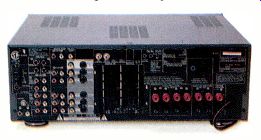
The VR-2090's outputs include an optical digital jack to pass the bit stream to another device and analog preamp jacks for the center and surround channels. The main front channels are hard wired to the built-in amplifier section, but there are left/right audio outputs and a composite -video jack for feeding an independently chosen program to a second room (dual-room/dual-source operation). The speaker outputs are closely spaced binding posts for two sets of main speakers, one pair of surrounds, and one center speaker, all of which accept wires and single (but not double) banana plugs. The rear -panel connectors are all base metal.
The second -room outputs are accompanied by other features that make the Kenwood VR-2090 very well equipped for multiroom operation and for custom installations. It has both an input and an output for an infrared transceiver in another room, enabling two way communication between the receiver and its remote controls.
There are also two outputs that re lay commands to remote infrared repeaters, a "TV On/Off Sensor" link that can be used to tell the VR-2090 when a monitor is on (ensuring proper operation of macros), and a relay -control output to operate projection-screen controllers or other external devices. Kenwood's connectors and control -signal levels are compatible with a number of third -party accessories, including those from Xantech and Niles. Two AC convenience outlets are also built in; their combined power rating is 90 watts.
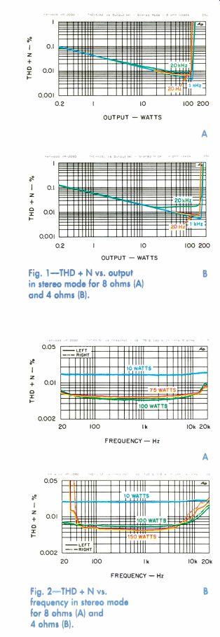
Fig. 1-THD + N vs. output in stereo mode for 8 ohms (A) and 4 ohms (B).
Fig. 2-THD + N vs. frequency in stereo mode for 8 ohms (A) and 4 ohms (B).
The Kenwood RC -R0907 PowerPad remote control that's packed with the VR 2090 is a multipurpose device, preprogrammed to operate many manufacturers' TVs, satellite receivers, cable boxes, VCRs, laserdisc and DVD players, CD players, and audio recorders. It even knows how to communicate with many home automation devices (such as X-10, Lutron, and Makita) for opening and closing drapes, lighting control, and so on. If the PowerPad doesn't have the codes for a particular product, they can be downloaded into it via an ordinary telephone.
If you're using an all-Kenwood system, matters are even simpler. Kenwood's remote-controlled products use one of two control modes (XS8 or SL16), both of which the VR-2090 accommodates. Set a rear-panel slider to the proper position, daisy-chain the control lines of the Kenwood equipment together, plug the cable into the rear of this receiver, and you're off to the races.
Kenwood's Power-Pad remote is one of the best I've seen included with a receiver.
It's a two-way system that issues commands to the RC -2090 and receives confirmation that they're being followed. The legend for whatever setting you're trying to modify doesn't change until the PowerPad gets word that the receiver has followed the instruction. This can be a little frustrating at first (who wouldn't get annoyed at a remote that sometimes seems to ignore commands?), but it's a great idea! I also like the fact that Kenwood makes proper use of LCD technology in the PowerPad, using the screen's ability to remap the display with alternative information while not succumbing to the temptation to make the screen touch -sensitive. Instead of pressing virtual buttons on the screen, you operate the PowerPad with five pushbuttons and a stubby, near -hemispheric joy stick that I call a joyball. The joyball falls naturally under your right thumb, assuming you grasp the remote in the right hand and rest it in the left, as right-handed people would do automatically. (Lefties may have problems with this remote and should check it out before buying.) Two of the pushbuttons adjust volume, a third mutes and un-mutes the receiver, another turns the system on and off ("On/Standby"), and the last ("Confirm") displays the receiver's current settings.
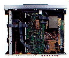
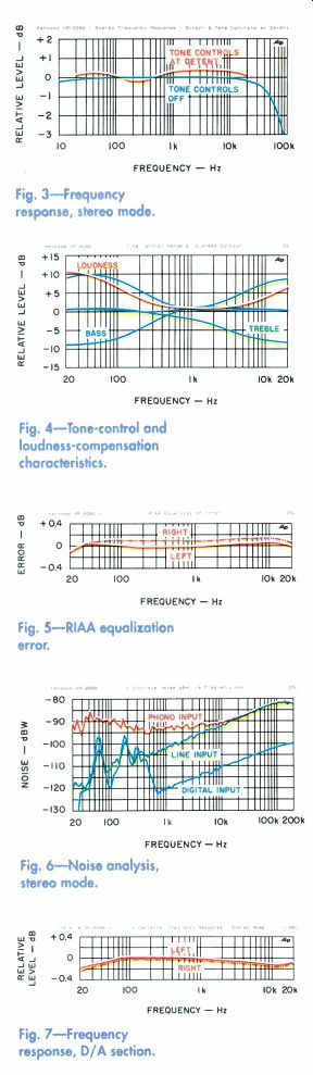
Fig. 3 --Frequency response, stereo mode.
Fig. 4-Tone-control and loudness -compensation characteristics.
Fig. 5--RIAA equalization error.
Fig. 6-Noise analysis, stereo mode.
Fig. 7-Frequency response, D/A section.
The PowerPad requires four AA cells.
Considering all the processing that goes on, I'd expect power consumption to be rather high, especially when the backlight is activated, but Kenwood says the PowerPad is certified for 40 hours of continuous use with alkaline batteries ("continuous" de fined as with the screen constantly illuminated and the remote constantly performing some activity). The screen is reasonably legible under decent lighting, so you'll probably need the backlight only when you've darkened the room.
The screen turns off after a few seconds of inactivity, presumably to conserve battery life, but goes on if you touch any button; touching "Confirm" turns it on without changing anything.
The remote uses a hierarchical structure similar to the nested menus of on -screen displays. But with this system, you can check and change settings without overlaying stuff on the picture or, for that matter, even needing a TV at all. I like that! The upper two lines in the PowerPad's screen always display icons for each of the ten program sources, two more to select the analog or digital audio input for sources that support both, and three to return to the main menu and to pull up the "Macro" and "Remote Mode" menus. Three of the PowerPad's macros, or control sequences, are programmable; the other four ("Video On," "Video Off," "Audio On," and "Audio Off") are preset.
The main menu has submenus for listening mode, sound, function, and setup. Listening mode choices include, for example, DTS, Dolby Digital, Dolby Pro Logic, Dolby 3 Stereo, DSP, and stereo.
The sound submenu is used for switching loudness compensation on and off, setting bass and treble controls and individual speaker levels, and controlling the two-step "Midnight Mode" dynamic range compression when playing Dolby Digital sources. The function sub-menu enables you to adjust the front -panel brightness and display mode and to control accessories and home automation modules.
And the setup submenu is used for everything from programming macros to adjusting surround -sound speaker configurations, balancing levels, and so on. All in all, the PowerPad is an unusually competent remote, but, needless to say, it takes some time to learn to use it to full advantage.
As usual, several setup menus relate to speaker size and bass management. Kenwood offers a quick setup procedure (in which you simply tell the VR-2090 whether or not you are using a subwoofer, center speaker, and surround speakers, and it does -60 the best job it can based on that in formation) and a custom setup procedure that offers far more choices (such as choosing the size of the front, center, and surround speakers separately). If you use a subwoofer, bass energy is normally redirected from those channels with speakers designated as "Small" to the sub, but there's also an "SW Re -Mix" option that routes bass to the subwoofer without removing it from the channels designated as having "Large" speakers.
Kenwood does digital bass management the way I think it should be done.
The VR-2090's RDS-equipped FM/AM tuner provides 40 station presets, automatic and manual tuning, and direct station access from the PowerPad remote. The receiver's power amplifiers use "Kenwood -developed K-STAT output transistors that are the first ever to incorporate the temperature sensor in the transistor itself." K-STAT is said to "instantaneously correct for transistor temperature changes, maintaining ideal performance characteristics in all operating conditions." That said, the VR-2090 as a whole is cooled by a thermostatically controlled fan.
Measurements:
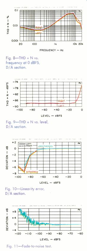
Fig. 8-THD + N vs. Frequency at 0 dBFS, D/A section.
Fig. 9-THD + N vs. level, D/A section.
Fig. 10-Linearity error, D/A section.
Fig. 11--Fade-to-noise test.
Following what has become common practice with A/V receivers, Kenwood restricts the VR 2090's FTC power rating (100 watts per channel, 20 Hz to 20 kHz, at 0.03% THD) to the main front channels, operated in stereo mode with 6 -ohm loads. In surround operation, each channel is rated only at 1 kHz (100 watts at 0.7% THD), again into 6 ohms. In point of fact, my sample beat those specs by a wide margin even when driving loads other than 6 ohms.
I tested the VR-2090 in stereo mode with both 8- and 4 -ohm terminations (and made a dynamic -power measurement using 2 -ohm loads). I didn't experience any problems, despite a statement on the back panel that warns against using speakers rated at less than 6 ohms. When driving a load impedance greater than that on which the power rating is based, an amplifier's output is usually limited by its power -supply volt age. For example, the output voltage that produces 100 watts into 6 ohms produces only 75 watts into 8 ohms. When the amp is driving load impedances below the rated value, the output power is usually limited by the current -handling ability of the output devices or by the devices that drive them. This limit is usually far less well de fined, so one must experiment to find a suitable rating.
To do this, I tested total harmonic distortion plus noise (THD + N) versus output at 20 Hz, 1 kHz, and 20 kHz using both 8- and 4 -ohm loads (Figs. IA and 1B). As you can see, the VR-2090's main -channel amplifiers can deliver just over 100 watts per channel into 8 ohms and somewhat more than 150 watts per channel into 4 ohms. (Clipping at 1 kHz occurs at 120 watts with 8 -ohm loads and 175 watts with 4 -ohm loads.) Next, I tested THD + N versus frequency, full -range, using 4- and 8 -ohm loads and three output levels (Fig. 2). In Fig. 2A, the 10 -watt curves are dominated by noise and are the least interesting. The other 8 -ohm curves were made at constant output levels of 75 watts per channel (the predicted "voltage -constrained" condition) and at 100 watts per channel (Kenwood's 6 -ohm rating).
Noise and distortion total less than 0.0089% across the board at 75 watts and barely more than 0.01% (one-third the 6 -ohm spec!) at 100 watts. Over most of the frequency range, the noise and distortion amount to less than 0.006% at either output level.
With 4 -ohm loads (Fig. 2B), at output levels of 100 and 150 watts, noise and distortion total less than 0.007% over most of the frequency range, though the distortion rises gradually above 5 kHz in both cases. At 20 kHz, the distortion measures 0.0175% at 100 watts per channel and 0.0248% at 150 watts. Below 40 Hz, the power supply has difficulty supplying the current needed to pump out 150 watts into 4 ohms, and distortion rises sharply.
Using the IHF tone burst, I measured dynamic output power of 175 watts per channel (22.4 dBW) with 8 -ohm loads, 210 watts per channel (23.2 dBW) with 4 -ohm loads, and 250 watts per channel (24 dBW) with 2 -ohm loads. Not bad for an amplifier that's not supposed to be connected to less than 6 -ohm loads! Dynamic headroom figures aren't included in "Measured Data" because Kenwood didn't specify continuous power into any of the loads I used. Damping factor was very high (550 at 50 Hz), and output impedance was not only low but remarkably uniform; the output impedance at 20 kHz was less than twice that at 50 Hz.
Figure 3 depicts the left front channel's frequency response measured with the tone controls set to "Off" and with them "On" but with both the bass and treble at "0." The ranges of the bass and treble controls are shown in Fig. 4, along with the effect of the loudness contour. (These measurements were all made in stereo mode.) It appears that Kenwood uses analog tone -control circuitry, because with the controls on but set flat, treble response extends well be yond the 24 -kHz barrier that usually applies to digital audio signals. Furthermore, the boost and cut curves are somewhat asymmetrical, and there's a modest response error with the controls in the circuit.
Although this doesn't bother me particularly, it is unusual in this day of digitally generated everything.
The tone -control range is limited to less than ±10 dB, which is just fine with me.
The loudness -compensation effect depends upon the volume set ting. I had the volume control at -27 dB for most tests because that was the setting corresponding most closely to the gain specified by the IHF standard. With that setting, however, the loudness compensation had no effect whatsoever; therefore, the curve in Fig. 4 was taken at a volume -control setting of -40 dB and rescaled to hit 0 dB at 1 kHz with the loudness compensation switched off. Switching it on shifts the entire curve upward a tad and ultimately produces a bass boost of 9.2 dB at 50 Hz and a treble boost of 5.6 dB at 15 kHz.
Compared with the phono pre-amps of many other A/V receivers, Kenwood's is quite remarkable. The equalization is unusually accurate (Fig. 5 shows the error plotted on a very sensitive scale), and the input impedance was well chosen for moving -magnet cartridges. Over load point was a relatively generous 145 millivolts, and the noise was quite low too. In Fig. 6 are third -octave spectrum analyses of the VR 2090's noise output through the phono, analog CD, and digital CD inputs. The absence of hum components in the phono noise spectrum is quite unusual considering the extra gain and bass boost provided by the preamp and RIAA equalizer. Al though some hum pickup can be seen in the CD input noise spectra, there's no power -supply component at 120 Hz, and the absolute levels of the 60- and 180 -Hz components (-102.2 and -98.5 dBW, respectively) are way, way down.
Overall, A -weighted noise measured from the analog CD input was admirably low, especially in view of the unusually high impedance that Kenwood uses for the line -level analog inputs.
FREQUENCY - Hz
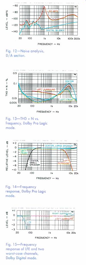
Fig. 12-Noise analysis, D/A section.
Fig. 13-THD + N vs. frequency, Dolby Pro Logic mode.
Fig, 14-Frequency response, Dolby Pro Logic mode.
Fig, 15-Frequency response of IFE and two worst -case channels, Dolby Digital mode.
Fig. 16-THD + N v., frequency, Dolby Digital mode.
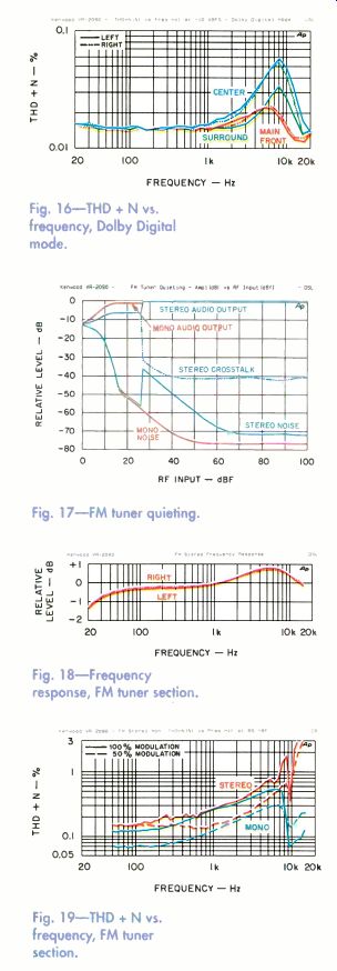
Fig. 17-FM tuner quieting.
Fig. 18-Frequency response, FM tuner section.
Fig. 19-THD + N vs. frequency, FM tuner section.
All results reported in "Measured Data" were taken using the "0" input -level setting in the setup menu. Kenwood provides two alternative choices, "-3" and "-6." The first of these drops overall gain by 2.1 dB and the second by 6 dB, but neither affects the input overload points in stereo mode: These re main 11.1 volts at the line -level in puts and 145 millivolts (at 1 kHz) at the phono input. The input -level setting does affect the overload point of the analog -to -digital (A/D) converter that is used for analog input in all modes other than stereo. For example, the line -
level analog input overload point in Dolby Pro Logic mode shifts from 2.22 volts at the "0" input -level set ting to 2.83 volts at the "-3" setting and to 4.42 volts at the "-6" setting.
All digitally processed signals must be converted back to analog before hitting the power amplifiers. In the Kenwood VR-2090, this is achieved with Crystal Semi conductor 20 -bit D/A chips. I evaluated the DACs independently of loo the DSP by coupling a PCM bit stream to the digital CD input and using the stereo operating mode.
Unfortunately, the DACs proved to be the weak link in this receiver.
Frequency response (Fig. 7) is fine. There's a slight error at each end of the audio band, but it's less than 0.2 dB and probably is in the power amps rather than the DACs anyway. There's no high -frequency response ripple, and that's good.
But as you can see in Fig. 8, full scale (0-dBFS) distortion begins climbing at frequencies above a few hundred hertz, peaking at approximately 0.07% in the 8 -kHz region. The number itself wouldn't
be all that bad, but the distortion is predominantly third -order and the curve would have continued to rise had the 22 -kHz filter in the analyzer not removed the offending harmonics at test frequencies higher than 8 kHz.
Figure 9 shows THD + N as a function of level with a 1 -kHz dig ital input. The results are worse than I would hope for, and I was forced to shift the vertical scale upward to accommodate the data. There was a time when a linearity error of 7 dB at -90 dBFS (as seen in Fig. 10) might have been considered par for the course, but it sure isn't today. Kenwood would be well advised to upgrade these DACs. Figure 11 shows linearity in the fade-to-noise test. Although worse than usual, it isn't as bad as might have been expected from Fig. 10. The fade curve is taken at a lower frequency than the regular linearity curve, which might explain the seemingly better performance.
The lower curve of Fig. 12 is a third -octave analysis of the output noise from a (`digital silence" input. (The same curve appears as the lowest one in Fig. 6, but there it's plotted as a power curve in dBW where as here it's referenced to 0 dBFS.) It's clear from the lie of this curve and from the weighted signal-to-noise ratios in "Measured Data" that the DACs mute when they recognize the silence code. The only noise remaining is that of the analog output amplifier, and that's very low indeed in the Kenwood VR-2090.
The upper curve of Fig. 12 is a third -octave analysis of the -60 dBFS, 1 -kHz signal used to evaluate dynamic range. The DACs remain active with this input, and the noise floor is 20 dB higher. The shape of the curve suggests that the converters are multibit types and don't use noise shaping; linearity is not their strong suit. Dynamic range and quantization noise measurements for the VR-2090 D/A converters were also poorer than average.
============
MEASURED DATA
AMP SECTION, STEREO MODE
Output Power at Clipping (1% THD at 1 kHz): 8 -ohm loads, 120 watts/channel (20.8 dBW); 4 -ohm loads, 175 watts/ channel (22.4 dBW).
Dynamic Output Power: 8 -ohm loads, 175 watts/channel (22.4 dBW); 4 -ohm loads, 210 watts/channel (23.2 dBW); 2 -ohm loads, 250 watts/channel (24 dBW).
THD + N, 20 Hz to 20 kHz: 8 -ohm loads, less than 0.0103% at 100 watts, less than 0.0089% at 75 watts, and less than 0.016% at 10 watts; 4 -ohm loads, less than 0.0248% at 150 watts (to 40 Hz), less than 0.0175% at 100 watts, and less than 0.0219% at 10 watts.
Damping Factor re 8 -Ohm Loads: 550 at 50 Hz.
Output Impedance: 14.9 milliohms at 1 kHz, 17.2 milliohms at 5 kHz, 21.6 milliohms at 10 kHz, and 27.3 milliohms at 20 kHz.
Frequency Response: With tone controls defeated, 20 Hz to 20 kHz, +0, -0.21 dB (-3 dB below 10 Hz and at 85.2 kHz); with tone controls at "0," 20 Hz to 20 kHz, +0.45, -0 dB (-3 dB below 10 Hz and at 65.2 kHz).
Tone - Control Range: Bass, +8.1, -7.6 dB at 100 Hz; treble, +7.4, -7.7 dB at 10 kHz.
Loudness Contour: +9.2 dB at 50 Hz and +5.6 dB at 15 kHz, with volume set at -40 dB.
Subwoofer Crossover: High-pass, -3 dB at 80 Hz and -6 dB at 61 Hz, 12-dB/octave slope; low-pass, -3 dB at 67 Hz and -6 dB at 82 Hz, 24-dB/octave slope.
RIAA Equalization Error, 20 Hz to 20 kHz: +0.06, -0.24 dB.
Sensitivity for 0-dBW (1 -Watt) Output: Line input, 22.2 mV; MM phono input, 0.29 mV.
Muting: Total.
A -Weighted Noise: Line input, -84 dBW; MM phono input, -79.8 dBW.
Input Impedance: Line input, 86.7 kilohms; MM phono input, 48.6 kilohms in parallel with 165 pF.
Input Overload (1% THD at 1 kHz): Line input, 11.1 V; MM phono input, 145 mV.
Channel Separation: Greater than 68.8 dB, 100 Hz to 10 kHz.
Channel Balance: ±0.015 dB.
Recording Output Level: Line (0.5-V in put), 491 mV; MM phono (5 -mV input at 1 kHz), 382 mV; FM tuner (100% modulation at 1 kHz), 670 mV.
Recording Output Impedance: 290 ohms.
AMP SECTION, DOLBY PRO LOGIC MODE
Output Power at Clipping (1 kHz), 8 -Ohm Loads: Main channels, 122 watts/channel (20.9 dBW); center channel, 145 watts (21.6 dBW); surround channels, 120 watts/channel (20.8 dBW).
THD + N at 100 Watts/Channel Output, 8 - Ohm Loads: Main channels, less than 0.0511%, 100 Hz to 20 kHz; center channel, less than 0.1137%, 100 Hz to 20 kHz; surround channels, less than 0.0795%, 100 Hz to 7 kHz.
Frequency Response: Main channels, 20 Hz to 20 kHz, +0, -0.36 dB (-3 dB below 10 Hz and at 23.4 kHz); center channel, "Large" speaker mode, 20 Hz to 20 kHz, +0.31, -0.38 dB (-3 dB below 10 Hz and at 23.6 kHz); center, "Small" speaker mode, 80 Hz to 23.6 kHz, +0.31, -3 dB; surround channels, below 10 Hz to 7 kHz, +0, -3 dB.
A -Weighted Noise: Main channels, -79.1 dBW; center channel, -79.4 dBW; surround channels, -80.4 dBW.
Channel Separation at 1 kHz: 39.1 dB or greater (84 dB maximum).
DOLBY DIGITAL (AC -3) MODE Channel Balance: 0.2 dB or better.
Frequency Response: Left front, 22 Hz to 20 kHz, +0.08, -0.19 dB; right front, 21 Hz to 20 kHz, +0.12, -0.21 dB; center, 21 Hz to 20 kHz, +0.35, -0.21 dB; left surround, 21 Hz to 20 kHz, +0, -0.2 dB; right surround, 22 Hz to 20 kHz, +0.46, -0.16 dB; LFE channel, 20 Hz to 66 Hz, +0, -3 dB.
THD + N at 1 kHz for 0-dBFS Signal: Left front, 0.0113%; right front, 0.0118%; center, 0.0181%; left surround, 0.0674%; right surround, 0.0148%; LFE (at 30 Hz), 0.0066%.
THD + N, 20 Hz to 20 kHz, for -10-dBFS Signal: Left front, less than 0.0228%; right front, less than 0.0236%; center, less than 0.0584%; left surround, less than 0.0337%; right surround 0.0539%.
Channel Separation: 62 dB or greater, 100 Hz to 10 kHz.
D/A CONVERTER SECTION Frequency Response: 20 Hz to 20 kHz, +0.03, -0.19 dB.
THD + N at 0 dBFS: Less than 0.0697%, 20 Hz to 20 kHz.
THD + N at 1 kHz: Below -75.5 dBFS from 0 to -90 dBFS and below -87.3 dBFS from -30 to -90 dBFS.
Maximum Linearity Error: Undithered signal, 6.75 dB from 0 to -90 dBFS; dithered signal, 7.39 dB from -70 to -100 dBFS.
S/N Ratio: A -weighted, 109.6 dB; CCIR weighted, 102.6 dB.
Quantization Noise: -87.5 dBFS.
Dynamic Range: Unweighted, 87.2 dB; A -weighted, 90.3 dB; CCIR-weighted, 80.8 dB.
Channel Separation: Greater than 68.8 dB, 125 Hz to 16 kHz.
FM TUNER SECTION 50 -dB Quieting Sensitivity: Mono, 19 dBf; stereo, 41.2 dBf.
S/N Ratio at 65 dBf: Mono, 75.6 dB; stereo, 69.4 dB.
Frequency Response, Stereo: 20 Hz to 15 kHz, +0.86, -1.27 dB.
Channel Balance: ±0.03 dB.
Channel Separation: Greater than 30.3 dB, 100 Hz to 10 kHz.
THD + N at 65 dBf, 100% Modulation:
Mono, 0.127% at 100 Hz, 0.269% at 1 kHz, and 0.568% at 6 kHz; stereo, 0.158% at 100 Hz, 0.275% at 1 kHz, and 0.723% at 6 kHz.
THD + N at 65 dBf, 50% Modulation:
Mono, 0.07% at 100 Hz, 0.127% at 1 kHz, and 0.306% at 6 kHz; stereo, 0.15% at 100 Hz, 0.156% at 1 kHz, and 0.482% at 6 kHz.
Capture Ratio at 45 dBf: 1.3 dB.
Selectivity: Adjacent -channel, 9.6 dB; alternate -channel, 70.9 dB.
Image Rejection: 48 dB.
AM Rejection: 64.9 dB.
Stereo Pilot Rejection: At 100% modulation, 66.9 dB; at 0% modulation, 67.7 dB.
Stereo Subcarrier Rejection: At 100% modulation, 60.9 dB; at 0% modulation, 93.1 dB.
============
Crosstalk between the left and right channels in stereo mode rose gradually with frequency. For the analog inputs, the range was from about -95 dB at 35 Hz to about -68 dB at 20 kHz in the worse (left -to -right) direction. Crosstalk via the digital inputs was a few decibels lower but followed roughly the same slope, which suggests that most of the crosstalk occurs in the analog output stages.
Figure 13 depicts THD + N plotted as a function of frequency in Dolby Pro Logic mode. For these curves, each channel was terminated with 8 ohms and the input was regulated to produce a constant output of 100 watts.
Since there was little difference in the data taken on the left and right front channels (or on the left and right surround channels), only the left -channel curves are included here. Distortion rises at frequencies above a kilohertz or so and peaks around 8 kHz before it diminishes again.
This is really the distortion of the D/A converters that follow the DSP-based Dolby Pro Logic decoder, not distortion in the power amplifiers.
When I measured THD + N as a function of output power in Pro Logic mode, the main front and the surround channels had essentially the same output power capability as the front channels in stereo operation. The center channel seemed more powerful than the others, but only because a center signal does not exercise the other channels and the center channel has the power supply all to itself during the test.
Figure 14 shows the frequency response of each channel in Dolby Pro Logic mode.
The curves for the three front channels extend smoothly to 20 kHz, whereas the surround channel rolls off above 7 kHz, in accordance with the Dolby Pro Logic standard. The bandwidth of the three front channels is limited to 23.5 kHz (give or take a few hertz) by the anti-aliasing filter that precedes the A/D converter. When making these response curves, I used both "Large" and "Small" center -speaker settings. These correspond to the old Pro Logic center -channel terminology of "Wide" and "normal," respectively. The "Small" center -channel curve actually depicts the response of the high-pass filter in the VR-2090's bass management system. The crossover frequency and filter slope are fixed rather than selectable, but they are very well chosen for most applications, fully meeting Dolby Labs' requirements and following Lucas -film's Home THX recommendations.
A -weighted output noise in Dolby Pro Logic operation was around -80 dBW, which is typical for an integrated amplifier or receiver in this mode. Steady-state separation at 1 kHz ranged from 39 to 84 dB. Overall, the separation averaged more than 60 dB, which should be adequate.
The worst crosstalk occurred between the surround and right front channels-better that way than the opposite! I used the Lucasfilm THX test DVD for most measurements of the Dolby Digital decoder, although I did use the Dolby Labs test disc to measure THD + N at 0 dBFS (1 kHz). There was a bit more variation in the responses of the five channels than usual, so the two "worst" curves are plotted in Fig. 15 along with the LFE response. By "worst," I mean the curves with the greatest deviation at 20 kHz. These happened to be for the two surround channels, which are arguably least important. But we're really splitting hairs here, since even the worst -case deviation is less than a half decibel.
Output levels were well matched, all within a total spread of ±0.14 dB. In general, THD + N at 1 kHz with the full-scale recording on the Dolby Labs DVD was about 0.015%. The left surround channel proved to be the exception; for some reason, the distortion in that channel was substantially higher (0.0674%). These measurements were made at a 10-watt output.
I also made THD + N versus frequency plots using the -10-dBFS recordings on the THX disc. The curves, which correspond to a 1 -watt output, are shown in Fig. 16. Again we see that the distortion rises above 1 kHz and peaks at 8 kHz before seeming to diminish. Clearly this is the same distortion discussed earlier, originating in the D/A converters.
Crosstalk in Dolby Digital mode aver aged around 70 dB at 10 kHz, the worst -case frequency. In the worst direction, it rose linearly from -90 dB at 50 Hz to about -58 dB at 20 kHz; in the best direction, the range was from about -92 to -75 dB. No problems here.
The VR-2090's tuner is surprisingly good. It's sensitive (19 dBf for 50 -dB quieting in mono) and quiet and has reasonably low distortion, a great capture ratio (1.3 dB), and excellent selectivity (almost 10 dB, adjacent channel, and 71 dB, alternate channel). Couple this performance with adequate AM rejection (nearly 65 dB), and you have a tuner that should do well under multipath-reception conditions. Image -rejection ratio (48 dB) was nothing to write home about, but that's seldom anything to fret about except near airports. Both pilot and subcarrier signals are well rejected, so recording on a cassette deck using Dolby noise reduction shouldn't be a problem.
Figure 17 shows the mono and stereo quieting curves. The tuner receives weak stereo broadcasts in mono and switches to stereo when the RF input reaches 27 dBf. At that point, 1 -kHz separation already exceeds 30 dB. By the time the tuner has achieved 50 -dB quieting in stereo-with a 41.2-dBf signal-separation exceeds 40 dB at 1 kHz. With a 65-dBf signal, separation is remarkably uniform across the entire audible range. With a standard 65-dBf RF input, signal-to-noise ratio exceeds 75 dB in mono and is almost 70 dB in stereo. With signal strengths greater than 70 dBf, stereo quieting reaches 71 dB, which is remarkably good.
The FM tuner section's frequency response (Fig. 18) is within ±0.9 dB from 25 Hz to 15 kHz, with a mild bass rolloff and an even milder mid -treble peak. The left and right channels are exceedingly well matched in level, too. Figure 19 shows THD + N versus frequency with a 65-dBf input in mono and stereo at 50% and 100% modulation. As tuners go these days, the curves for the VR-2090 aren't bad at all.

Use and Listening Tests
Boy, do I feel like I'm on the horns of a dilemma. The Kenwood VR-2090 is one of the best-conceived-maybe the best conceived-A/V receivers I've played with. It's got lots of inputs, and every composite -video connection is doubled with an S video counterpart. It doesn't handle component video, but no receiver I know of does. It doesn't have a digital audio connection for every input, but it offers either a wired or optical input on four (CD and three A/V sources), which should take care of most situations. It also has an optical digital output.
The VR-2090 can feed a separate pro gram to a second room; with the right accessories, you can even control it from there. It has a really appealing and extraordinarily competent remote that controls not only the VR-2090 but also a host of other components and home automation products. Raise and lower the room lights, the window shades, the projection screen; I'm sure you can turn on your coffee maker with the right accessory. The only thing I'd change about the PowerPad remote is to have its display stay on a little longer than it does when quiescent.
The VR-2090 has great analog electron ics, power amps that will be comfortable in any circle, an unusually competent RDS FM tuner. It decodes just about anything you'd be likely to toss at it (Dolby Pro Logic, Dolby Digital, DTS), has the normal complement of simulated -ambience doo dads, and does bass management correctly.
On the other hand, it's got some really punk DACs and a noisy fan that comes on far too readily! This receiver has got so much going for it, it's almost in a class by itself. But when I play good program material and use revealing speakers, I can hear the imperfections in the DACs. Detail gets lost, the natural ambience of the recording is truncated, and listening fatigue sets in sooner than I think it would with cleaner converters.
Will you hear this? I don't know. I think it will depend upon your speakers, the type of music you listen to, and how well that music is recorded. I doubt that the DACs will be particularly bothersome in the aver age home theater, especially on boom -bang -shoot 'em -up movies. You're most likely to object to the DACs when listening to classical music. And, maybe not then.
Nor can I predict whether the fan will do its thing regularly in your system. That, too, will depend on the speakers, how loud you play them, and how well ventilated you keep the VR-2090.
This is a receiver that you're going to have to judge for yourself and decide whether its very real positives outweigh the potential negatives. I'll say this for it: The Kenwood VR-2090 deserves a chance. It has too much going for it to be dismissed be cause of a few foibles.
--------------------
by BASCOM H. KING
QUICKSILVER AUDIO SILVER 60 MONO AMP
Rated Output: 60 watts.
Dimensions: 15 in. W x 6 1/z in. H x 9 34 in. D (38.1 cm x 16.5 cm x 24.8 cm).
Weight: 36 lbs. (16.3 kg).
Price: $2,350 per pair.
Company Address: 5635 Riggins Court, #15, Reno, Nev. 89502; 702/825-1514;
www.quicksilveraudio.com.
At first glance, the Quicksilver Audio Silver 60 looks a lot like the Quick silver V4 amplifier I tested a year ago (February 1998). Internally, however, it's a rather different beast. The Silver 60 is Quicksilver's response to a speaker manufacturer's re quest for a tube amp that could drive difficult loads and still sound good. But this push-pull design also incorporates lessons that Mike Sanders, Quicksilver's chief designer, learned from low -power, single -ended (SE) triode amplifiers.
Initially, Sanders was skeptical about SE amps because of their generally poor measured performance. Ultimately, he realized that the best models' virtues-amazingly good dynamics and clarity and bass with equally good impact, extension, and definition-justified further research. Much of the improved low bass, he found, came from using oversized output transformers, whose primary windings had high enough inductance for efficient low -frequency coupling to the power tubes. (Low -inductance primary windings cause poor low -frequency performance with demanding speaker loads.)
According to Sanders, further experimentation with tube operating points, circuit topology, component values, and other parameters yielded a more dynamic sound and powerful bass, much like the best SE amplifiers. These changes sacrificed certain measured parameters in order to improve load -driving ability and duplicate some of SE designs' desirable sonic attributes in an amp that retained the higher power of push-pull.
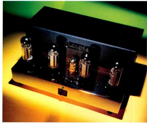
Visually, the Silver 60 has a simple elegance, its black rear cover (which houses the power and output transformers and two filter capacitors) making a pleasing contrast to the chrome chassis. Four output tubes and a small input tube rise from the chassis' projecting apron. The only control features are a large on/off rocker switch and a green LED pilot light on the front of the apron; the output circuit is self -biasing, so no bias adjustment is provided. The rear panel holds a screw -terminal barrier strip for speaker connections (with taps for 1, 4, and 8 ohms), an RCA input jack, an AC line fuse, and an IEC power -cord socket.
The Silver 60's construction is simple, elegant, and traditional. The wiring is point to-point, with Quicksilver's typical neat ness, using the chassis as the ground bus.
Parts are of a high quality. All in all, a very nicely made amp.
=============
ASSOCIATED EQUIPMENT USED
Equipment used during the listening test sessions for this review consisted of:
CD Equipment: Classé Audio DAC 1 and Sonic Frontiers Processor 3 D/A converters, PS Audio Lambda Two Special and Sonic Frontiers Transport 3 CD transports, Sony CDP-707ESD CD player, Panasonic DVD-A310 DVD player, and Genesis Technologies Digital Lens anti -jitter device Phono Equipment: Kenwood KD 500 turntable, Infinity Black Widow arm, Win Research SMC-10 moving -coil cartridge, and Vendetta Research SCP2-C phono preamplifier Additional Signal Sources: Nakamichi ST -7 FM tuner, Nakamichi 1000 cassette deck, and Technics 1500 open-reel recorder Preamplifiers: Sonic Frontiers Line -3 and First Sound Reference II passive, modified Quicksilver Audio LS, and Dynaco PAS -2 Amplifiers: Arnoux Seven -B stereo switching amp, Quicksilver Audio M135 mono tube amps, Manley Labs Stingray stereo tube amp, de Havilland Electric Company Aries single -ended mono tube amps, E.A.R. V20 integrated tube amp, and Sumo Polaris solid-state stereo amp Loudspeakers: Dunlavy Audio Labs SC-IIIs and Tannoy Churchills Cables: Digital interconnects, Illuminati DX -50 (AES/EBU balanced); analog interconnects, Vampire Wire CCC/II and Tice Audio IC -1A; speaker cables, Kimber Kable Bi-Focal-XL and Madrigal Audio Laboratories HF2.5C
=============
TECHNICAL HIGHLIGHTS
The circuit of the Quicksilver Audio Silver 60 is as close to minimal as it can get and still be practical. Signal input is applied to the common -cathode first stage, using half of a 12AT7 twin triode. That stage's plate output is directly coupled to the grid of the second stage, a split -load phase inverter, which uses the other half. The phase inverter's outputs are capacitor -coupled to the control grids of the output tubes.
Two paralleled push-pull pairs of output tubes are used, in an Ultra -Linear circuit configuration. These tubes should have a long useful life, as four of them are used even though power output is relatively low. A common cathode resistor, bypassed with a capacitor, provides self -biasing (cathode bias). The Silver 60 comes with EL34 output tubes, though other types (such as KT88s, 6550s, or 6L6s) can be used. The plate -to -cathode voltage is some what lower than is the norm nowadays, on the order of +385 volts.
Current draw, while not terribly high, is higher than Quicksilver's norm: With EL34s, it's around 55 milliamperes per tube, for output stage dissipation of some 84 watts at idle. Setting the output circuit's operating points for lower voltage and higher current than customary was part of the amplifier's voicing. Over all feedback is taken from the 8 -ohm connection on the output trans former back to the cathode circuit of the first stage.
B.H.K.
===============
Measurements
Unless otherwise noted, all reported results are for the Silver 60 amplifier I used in the left channel (which was distinguished from the other amp by a white band on its input jack); results for both amps were very similar.
Frequency response at the 8 -ohm tap is shown in Fig. 1A, response at the 4 -ohm tap in Fig. 1 B. In each case, I used the NHT dummy speaker load, an open circuit, a matching load (8 ohms on the 8 -ohm tap, 4 ohms on the 4 -ohm), and a resistance of half that load (4 and 2 ohms, respectively).
The curves for the 4 -ohm tap are a bit closer together, signifying slightly better output regulation with load and a slightly B higher damping factor at that tap.
(This is because the turns ratios of many output transformers, including the Silver 60's, yield 9- and 4 -ohm taps rather than 8- and 4 -ohm.)
The Quicksilver's square -wave response (Fig. 2) is fairly good at 10 kHz into an 8 -ohm resistive load on the 8 -ohm tap, and the absence of the usual overshoot, ringing, and increased rise time when a 2 microfarad capacitor is paralleled across the load is commendable.
(Thus, the Silver 60s would be a good choice for driving electrostatic speakers.) The amp's excellent low -frequency response can be gleaned from the small amount of tilt in the 40 -Hz trace. Rise and fall times for a ±5 -volt output into an 8 -ohm load on the 8 -ohm tap were 2.8 microseconds; with a 4 -ohm load on the 4 -ohm tap and the same input drive level, the results were 3.1 microseconds.
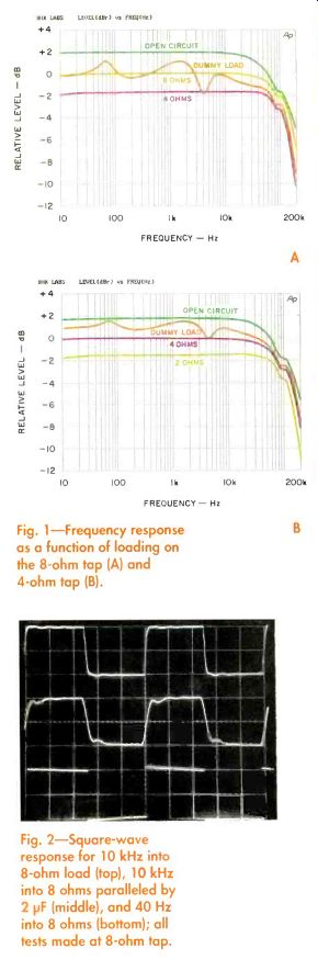
Fig. 1-Frequency response as a function of loading on the 8 -ohm tap (A) and 4 -ohm tap (B).
Fig. 2-Square-wave response for 10 kHz into 8 -ohm load (top), 10 kHz into 8 ohms paralleled by 2 NF (middle), and 40 Hz into 8 ohms (bottom); all tests made at 8 -ohm tap.
Figures 3, 4, 5, and 6 show several aspects of distortion, all measured at the 8 -ohm tap. Figure 3 plots two types of distortion versus power, total harmonic distortion plus noise (THD + N) at 1 kHz for various loads and SMPTE IM distortion for an 8 -ohm load. In Fig. 4, THD + N versus frequency at several power levels, there's a commendably small increase in distortion at each end of the audio spectrum. Figure 5 reveals that the second and third harmonics are dominant through most of the output range and that the fourth and fifth harmonics are essentially out of the picture until about 20 watts. Except for the sixth harmonic, which attains almost the same level as the fourth at 10 watts out (Fig. 6), the higher harmonics drop fairly rapidly to very low levels. The Silver 60's overall measured distortion was not as low as that of some past Quicksilver amps. This is primarily because of the newer circuit's simplicity, the small amount of global feedback, and the designer's optimization of circuit operating points for best sonic performance rather than lowest measured distortion.
As you can see in Fig. 7, the Silver 60's damping factor is relatively constant over the frequency range, even in the low bass, at the 8 -ohm tap. Although the 4 -ohm curve's shape was very similar, overall damping factor was a bit higher, about 4, because of the improved output regulation at that tap.
Dynamic power at the start of the 20 -millisecond IHF tone burst was 68 watts, yielding dynamic headroom of 1.1 dB, but dropped to 64 watts by the end of the burst.
With a 1 -kHz tone, the amps started to clip at about 58 watts, yielding clipping headroom of -0.3 dB.
Voltage gain into 8 -ohm loads on the 8 -ohm tap was 24.79 dB for the amp I used for the left channel and 24.88 dB for the amp I used for the right; corresponding IHF sensitivity for 1 watt into 8 ohms was 163 and 161.3 millivolts, respectively.
Output noise for the left -channel amp was 537.2 microvolts wideband and 99.8 microvolts A -weighted; for the other amp, the results were 873.9 and 126.6 microvolts. The IHF signal-to-noise ratio was 89 dB for the left channel and 87 dB for the right. The AC line current was 1.44 amperes at idle, increasing to 1.7 amperes at 58 watts into 8 ohms on the 8 -ohm tap.
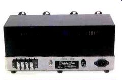
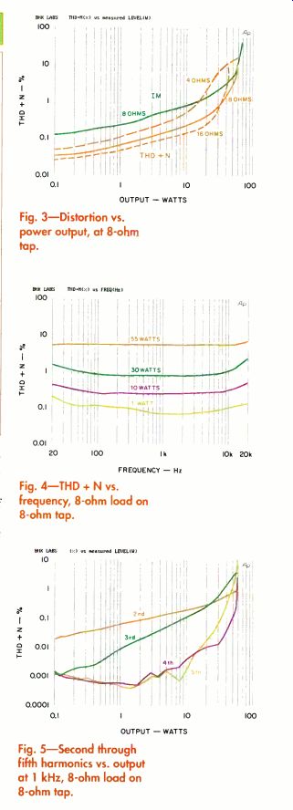
Fig. 3-Distortion vs. power output, at 8 -ohm tap.
Fig. 4-THD + N vs. frequency, 8 -ohm load on 8 -ohm tap.
Fig. 5-Second through fifth harmonics vs. output at 1 kHz, 8 -ohm load on 8 -ohm tap.
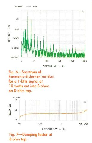
Fig. 6-Spectrum of harmonic -distortion residue for a 1 -kHz signal at 10 watts out into 8 ohms on 8 -ohm tap.
Fig. 7-Damping factor at 8 -ohm tap.
Use and Listening Tests
For my initial listening, I used the Quick silver Silver 60 amplifiers to drive a pair of Dunlavy Audio Labs SC -III loudspeakers (which I reviewed in the July 1998 issue), augmented by a pair of Tannoy Churchill speakers used as subwoofers; the Churchills were driven by a Sumo Polaris stereo power amp via a custom low-pass filter whose input was the output from the Quicksilvers. My preamp for this setup was the First Sound Reference II.
When I received the Silver 60s, they were quite new, with virtually no playing time on them. They sounded good right out of the box, but I knew they would sound a bit better with more hours on them.
And indeed, when I set them up for further listening after I'd made my measurements, they sounded even better.
I was quite impressed with the Silver 60s. Their transparency, space, air, and dimension were right up there with the best. Bass quality, impact, definition, and extension were also quite impressive.
The Quicksilvers drove the Dunlavy SC-IIIs with enough power to play most of my favorite music at considerably higher volume levels than those I use for normal listening. And when I replaced the SC-IIIs with the Churchills, which are 4 dB more sensitive, the Silver 60s made these Tannoy speakers really stand up and shout!
Whether I used the Dunlavy/Tannoy set up or the pair of Tannoys alone, the Quicksilvers sounded amazingly natural and convincing.
The Quicksilver Silver 60s did their thing most competently and without problems.
My only surprise was at how good these little amps were. I liked them a lot, enjoyed a lot of music with them, and most definitely recommend your giving them a listen.
(Audio magazine, 1999)
Also see:
AURICLE --MSB TECHNOLOGY LINK D/A CONVERTER; CREEK 4330SE INTEGRATED AMP
THE AUDIO INTERVIEW -- Bob Carver--the boy wonder...all grown up
ABZ's of Stereo FM--Modern Switching-Circuit Decoder
How Disc Masters Are Made Today
H. H. Scott, Inc. Perfectune (ad)
Tape Transport Maintenance--Part 3
= = = =