by NORMAN H. CROWHURST
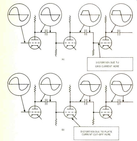
Fig. 14-1. Deductions from stage-by-stage waveform measurement. At (A) the distortion first shown between the 2nd and 3rd stages is due to grid-current loading by the 3rd stage. At (B) a quite similar (but not identical) effect is due to curvature (approaching cut-off) in the 2nd stage.
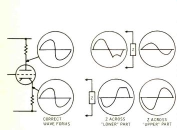
Fig. 14-2. Some of the peculiarities that may show up in measurements associated with split-load phase inverters (here shown with tube). In each of the pairs of waveforms, center and right, the "Z" represents the location of the measuring instrument (voltmeter, scope, or both), while the waveforms are those at both places while the instrument is so connected.
ALL THE MEASUREMENTS discussed in earlier installments concern complete units of equipment: we have not discussed the making of measurements where you have to get "inside" an item of equipment, for either service or development purposes. Yet both of these uses are important in audio work.
Measurements on the old-fashioned tube amplifiers were relatively simple.
although some erroneous conclusions could be drawn even there from incorrect interpretations of the voltage indications observed, using either a voltmeter or a scope. But the transistor circuits multiply the possibility for such misinterpretation, which is one reason why transistors took so long to find extensive application in audio work.
Voltage Readings, Tubes and FET's
We shall regard tubes and FET's (Field Effect Transistors) as essentially similar, because for measurement purposes they have both the same kind of characteristics. Both are essentially voltage amplifiers, or devices in which the controlling input signal is a voltage rather than a current.
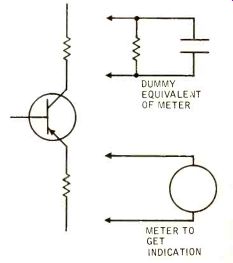
Fig. 14-3. If duplicate identical instrumentation cannot load both outputs
of the split-load inverter identically, use a dummy, so the loading is
identical while each measurement is made.
Only one measurement (across emitter half of load) is shown here. Reverse places to measure other half.
The kind of mistakes sometimes made are obvious-once you have either made them and found your own mistake, or else had them carefully explained to you. Two examples will illustrate. The first relates to finding out where distortion occurs in a multistage amplifier (Fig. 14-1). Checking waveform at various points through an amplifier shows that flattening first occurs at a certain point.
The logical--obvious, but often erroneous-deduction is that the distortion occurs in the stage between the latest point where no distortion is indicated and the one where it first appears. Quite often it is not in this stage at all, but the one following it is the cause. In tube circuits, grid-current loading will flatten the output of the previous stage, although without this loading it would show no distortion at all at this point.
On the other hand, if the distortion is due to cut-off, rather than saturation (grid saturation) , the reverse situation applies: the distortion will show ...
------
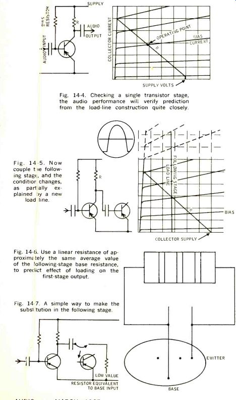
Fig. 14-4. Checking a single transistor stage, the audio performance
will verify prediction from the load-line construction quite closely.
Fig. 14-5. Now couple tie following stags, and the condition changes, as part ally explained oy a new load line.
Fig. 14-6. Use a linear resistance of approximately the same average value of the following-stage base resistance, to predict effect of loading on the first-stage output.
Fig. 14-7. A simple way to make the substitution in the following stage.
--------
... following the stage running into cutoff, not before it [(B) in Fig. 14-1].
The other frequent cause of error in simple amplifier measurements concerns phase-inverter balance (Fig. 14-2). Voltmeters and scopes used nowadays have high input impedances, that do not appreciably load the circuits to which they are connected. But they may have a capacitive input, if only due to the shielded input lead, that produces an effect that is not quite negligible.
Several things can happen. First the loading caused at high frequencies may destroy balance at those frequencies, although such loss of balance does not occur until the external load (due to the measuring device) is connected. This may have a greater effect on one half of the push-pull than the other, due to asymmetrical internal impedance, and thus cause an indicated lack of balance that does not actually happen until the voltmeter or scope is connected.
Also the instrument loading may unbalance the circuit to a point where the "other half" of the load reaches saturation and reflects a change of waveform into the measured half that does not otherwise occur. The best way to guard against these misleading indications is either to use identical instrumentation to measure both sides of the inverter output simultaneously, or to make up a simulated input circuit, so each can be measured with the "other side" similarly loaded (Fig. 14-3). Current Amplification, Transistors Those things, and more like them, are "old hat" to most readers. Now we turn to the problems that only begin to show when we start using circuits primarily built around current amplification, with transistors. If you just dive in and start making waveform and voltage measurements, the results may be very puzzling at first.
To make the picture clearer, we'll assume you are starting from scratch, because it's easier to understand that way.
Suppose you are checking out a simple amplification stage (Fig. 14-4). Bias is chosen to ensure maximum available swing in each direction, so the collector voltage is approximately half the supply voltage, and an input resistance may be used to simulate the driving impedance of a preceding stage. The previous stage, we'll presume, behaves according to prediction--it probably will.
Now we couple the next stage (Fig. 14-5) . Three things may now happen: first, the voltage swing disappears, because the following stage loads the collector circuit right down; second, what voltage is left is quite distorted, mainly because the input resistance of the following stage is quite non-linear (even when its amplification is linear); and third, it may be found that the first stage is running into overload at an input level considerably lower than it could handle successfully before the second stage was coupled.
To check, approximately, the true performance of the first stage when loaded by the second, either the current delivered to the second stage must be measured, which is never as easy to do as measuring voltage and its waveform; or the voltage can he measured across a linear resistance of approximately the same value as the average input resistance of the following stage (Fig. 14-6) . If plug-in transistors are used, inserting of such a substitute resistor value for measurement can readily be achieved by removing the transistor and pushing a pair of wires (of the same gauge) cut from new transistors, into the base and emitter sockets. To these wires an appropriate low-value resistor is soldered, across which the waveform can be measured (Fig. 14-7). This measurement will separate the three effects for ready analysis. Both voltage swing and current swing can now be determined at this point. Voltage swing is measured directly, but means little, because the linear resistance across which it is measured is in reality a substitute for a non-linear resistance which will change both the value and magnitude of the voltage waveform. But the waveform across the substitute resistor will be reliable indication of current waveform, and its magnitude can be calculated from the resistance value used.
If the loading down by this low input resistance representing the following stage asymmetrically increases current swing of the stage being measured (Fig. 14-5), this will allow excessive level and/or distorted waveform to occur at this point, which can be observed across this substitute resistor. Where this occurs, the original current swing (without the loading) can be restored by changing the collector resistor R so collector voltage is much lower, but the same current swing is available (Fig. 14-8). Usually the collector resistor needs to he almost double, but the bias remains almost the same (in current), However, an improved way of obtaining it is to employ voltage feedback, which controls voltage of the operating point without causing appreciable current feedback (Fig. 14-9). The bias resistor will need to have about 1/10th the value needed for the condition of Fig. 14-4.
Putting Stages Together
Operating individual stages under independently simulated conditions, both for source and load resistance, can take a big step toward securing correct operating conditions throughout a multistage amplifier. But things can still happen when stages are connected together that do not show up when the stages are checked separately. This may not seriously invalidate the over-all projected performance, but is far more likely to do so where feedback parameters are involved.
Individual stages can be checked for current gain, available swing, and the cut-off points of coupling networks by this substituted-load process.
Tolerably linear values, such as collector-circuit resistances, are arranged to swamp the effects of non-linear resistances, such as base inputs. If necessary, emitter resistors can to some extent linearize effective base input resistance (Fig. 14-10) by adding an approximately linear value found by multiplying their actual value by the working current gain of the transistor.
So far, so good, but now, when you put the whole thing together, the total response is not the sum of its parts.
Maybe the mid-hand current gain adds up nicely, but the frequency turnovers on which the feedback stability or over-all effect is based don't add up so nicely.
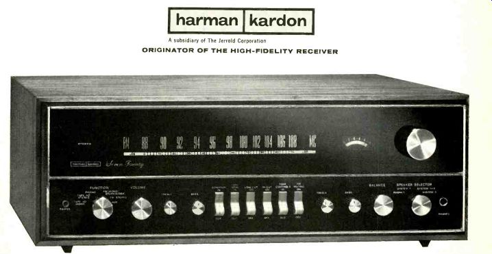
This is because transistors reflect impedance both ways, as well as contributing current and voltage gain. For the emitter-follower (common-collector) stage, this reflection is fairly simple and predictable: impedances, including resistance and capacitance (or inductance, if present) effects are multiplied or divided by the operating current gain of the stage (Fig. 14-11). This can be checked by impedance measurement, each way Fig. 14-12) . There are limits to which this reflection effect follows with any accuracy, even in an emitter follower, which coincide reasonably well with the limits at which its current gain begins to change. This too is fairly predictable and verifiable by measurement.
But most amplifier stages use the common-emitter configuration, which alters the picture. In this mode, the input resistance is lowest when the output load is highest ( voltage swing highest) so as to approximate constant-current output ( voltage rather than current output). When the output is loaded down so output voltage no longer swings, but there is a maximum output current swing, the reflected input impedance is much higher.
This means that output load reflects into the input circuit as an inversion:
high value reflects as a low value, and inductance looks like capacitance, and vice versa. A series capacitor (coupling) reflects an impedance component similar to shunt inductance, and so on.
The same thing happens in the reverse direction, to reflected collector impedances, due to actual base-circuit elements.
------------
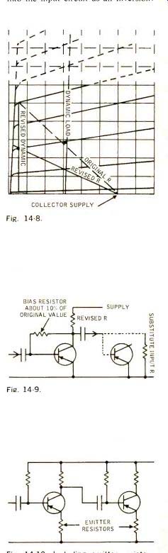
Fig. 14-8. Changing the collector coupling resistor
to get back to the proper conditions, when the following stage is coupled.
Dashed lines show the condition of Fig. 14-5 repeated for comparison
with the revised condition, in solid lines.
Fig. 14-9. A better way of deriving bias, (one that provides voltage feedback), to stabilize the working position shown in Fig. 14-8, without producing appreciable current feedback, in the output-loaded-down condition.
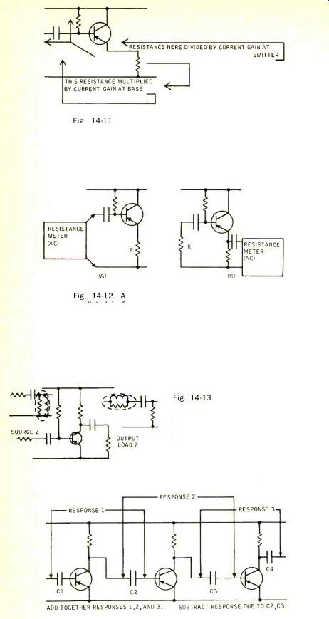
Fig. 14-10. Including emitter resistors to stabilize, or linearize, the base-input resistance reflected to the previous stages.
Fig. 14-11. In an emitter follower, resistances and impedances are reflected both ways, multiplied or divided by the working current gain of the stage, with considerable faithfulness.
Fig. 14-12. A method of checking the results predicted in Fig. 14-11 by actual measurement. The resistance meter should measure a.c. resistance and in (B) provide a current path. In each case, the resistance meter will measure the reflected value change when the real value R is changed.
Fig. 14-13. Equivalent circuit reflection with common-emitter stage. The inset schematics represent the equivalents for the circuit in that "side" of the stage. The elements in the dashed lines are those representing reflected values from the other side.
Fig. 14-14. For reasonable prediction, each stage should be measured with both coupling elements included (responses 1, 2, and 3). When adding the results together, the duplication must be eliminated by subtracting the effects of C2 and C3.
----------------
The equivalent circuit makes it look as if resonance, in either base or collector circuit, if not both, inevitable (Fig. 14-13). But the relative values preclude actual resonance effects. The reflected elements (in this case inductive, due to actual capacitance) are invariably of changing magnitude equivalent to an inductive reactance that does not represent a simple inductance value) and always of an order well removed from resonance, so they merely effect a progressively changing effective value for the actual circuit capacitances.
If prediction is attempted in any terms at all, it should be on the basis of magnitude and phase response, rather than on equivalent circuit values, which are continuously changing with frequency. A careful series of measurements on a stage-by-stage basis can help "put the circuit together" but the prediction is limited, because stages can only be measured integrally: each with both of its equivalent coupling elements; when the whole circuit is "put together," each coupling element is present in relation to both the stage preceding it and the one following it.
If, from the measured stage-by stage responses, added together, the theoretical effects of the individual coupling networks, which are thus included twice each (except the first and last) as part of the preliminary measurements, are subtracted from the whole, an approximation close to the true over-all effect will be predicted, on which over-all feedback parameters can be later figured (Fig. 14-14). Even then, the over-all effect may differ from prediction, as more feedback is applied, because the relative input and output levels are changed at the couplings to those stages, so the response contributed in the presence of feedback differs from that contributed by the same elements in the absence of feedback, or with less of it.
This whole procedure, to be effective, requires close working between measurement and calculation at every stage, to approach a practical operating circuit design. In the next installment we shall pursue this further, by detailing some practical feedback "cutting and fitting."
+++++++++++++
ID-19E/200 is a cardioid microphone for high quality recording and sound reproduction, and provided with bass roll-off switch for exceptionally clear speech intelligibility and excellent output for above average "reach." It features effective front-to-back discrimination and a nonmetallic diaphragm-preventing popping and harshness on close-ups.
TECHNICAL DATA
Frequency range Frequency response Sensitivity Impedance Dimensions Weight 40-16,000 cps. ±3db -53db 200 ± 20%, 7 1/4" long by 1 3/8" diameter 7 ounces Here are two economical microphones for a variety of recording, broadcast and public address applications. An accessory W-24 Windscreen is available for the D-19E/ 200; also fits the D-24E microphone.
Truly noise canceling, the D-58E microphone is the ideal choice for sportscasts, industrial uses or any similar noisy environment.
Send today for data sheets and prices.
D5 8 E is a noise-cancelling microphone limited to the speech range and offers crisp, clear speech reproduction, for maximum intelligibility. It effectively discriminates against any sound originating beyond 5" from the microphone.
TECHNICAL DATA
Frequency range Sensitivity Impedance Dimensions Weight Goose neck 70-12,000 cps.
-58db 200or60 ohm ± 15%
MADE IN AUSTRIA BY AKG GMBH. Norelco PROFESSIONAL SOUND PRODUCTS NORTH AMERICAN PHILIPS COMPANY, INC. Professional Products Division, 100 East 42nd St.. New York. N. Y. 10017
+++++++++++++
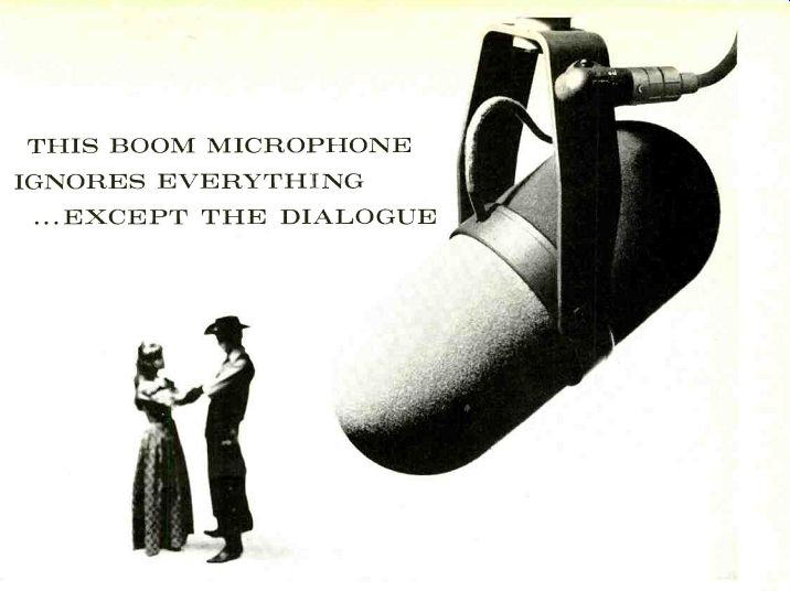
THIS BOOM MICROPHONE IGNORES EVERYTHING
...EXCEPT THE DIALOGUE Consistency of sound track quality on an endless variety of locations and sets can be dramatically improved with the remarkable Shure SM5 Boom Microphone. It "hears" the dialogue rather than the ever-changing character of the surroundings.
Because its cardioid directional pattern is uniquely uniform with frequency and symmetrical about its axis, the SM5 is singularly independent of the effects of environment. Even in extreme shooting situations (such as with tight sets, low ceilings, hard walls, low microphone angles, traffic or air conditioner noise and rumble, and changing distance) the SM5 minimizes sound coloration and ambient noise pickup. Equalization changes-on the set or in transfer-are seldom, if ever, necessary.
The highly effective attached windscreen completely encloses the two-stage mechanical filter, so that there are no external "rubber bands" for the wind to "strum." The absence of response-correcting inductors or impedance transformers assures freedom from hum.
Call on the Shure SM5 to solve your most annoying boom problems! For additional information, write directly to Mr.
Robert Carr, Manager of Professional Products Division, Shure Brothers, Inc., 222 Hartrey Ave., Evanston, Illinois.
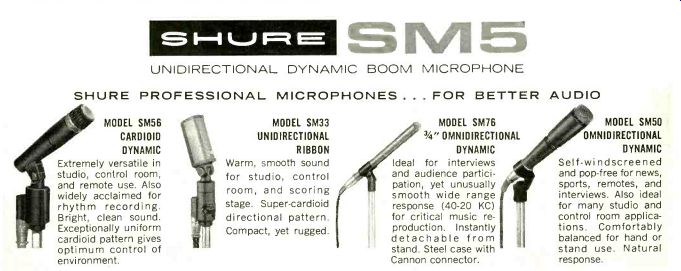
M5 UNIDIRECTIONAL DYNAMIC BOOM MICROPHONE SHURE PROFESSIONAL MICROPHONES . . . FOR BETTER MODEL SM56 CARDIOID DYNAMIC Extremely versatile in studio, control room, and remote use. Also widely acclaimed for rhythm recording.
Bright, clean sound.
Exceptionally uniform cardioid pattern gives optimum control of environment.
MODEL SM33 UNIDIRECTIONAL RIBBON Warm, smooth sound for studio, control room, and scoring stage. Super-cardioid directional pattern. Compact, yet rugged.
MODEL SM76 34" OMNIDIRECTIONAL DYNAMIC
Ideal for interviews and audience participation, yet unusually smooth wide range response (40-20 KC) for critical music reproduction. Instantly detachable from stand. Steel case with Cannon connector.
AUDIO MODEL SM50 OMNIDIRECTIONAL DYNAMIC Self-windscreened and pop-free for news, sports, remotes, and interviews. Also ideal for many studio and control room applications. Comfortably balanced for hand or stand use. Natural response.
+++++++++++++
Meet the Mediterranean, the speaker she won't have to hide to enjoy.
Here at last is cabinetry she can revel in. Rich. Striking. Its deeply grained exterior hand-rubbed to a mellow butternut finish .... accented with antique hardware.
And inside . . . the finest 3-speaker system with Sonic-Control.
But let her see it, hear it for herself. It's Mediterranean the one both of you can live with on demonstration now at University dealers everywhere!
SPECIFICATIONS: 12" ultra-linear woofer, 8" solid-back mid-range, reciprocating flare horn tweeter-20 Hz to beyond audibility 50 watts IPM (Music Power) 8 ohms-1/a and 1/2 sections, 6 and 12 db/octave electrical network 800 and 5000 Hz crossovers continuously variable Brilliance and Presence controls, 3-position variable bass switch-24 3/8" dia., 22 1/2" high-Shipping weight, 74 lbs.
Desk C-73
UNIVERSITY SOUND
A DIVISION OF LTV LING ALTEC. INC. 9500 W. Rena, Oklahoma City, Oklahoma 73101
+++++++++++++++
For the clearest, strongest FM stereo: MOSFET What's the ultimate goal in tuner design? To pull in the clearest, strongest signal from distant and nearby stations-with minimum noise, cross-modulation, and distortion.
You may recall that, in the early 1960's, the nuvistor triode, first used in Harman-Kardon's Citation Ill tuner, represented the state of the art in low-noise, ultra-sensitive front-end designs. Then, a few years later, we were first to discard the nuvistor tube in favor of an all-transistor FM front end of outstanding performance.
Since that first all-solid-state front end, you've heard a lot about newer transistors (field-effect transistors) that further improve FM reception. While early FET's were satisfactory in comparison with previous devices, the difference in over-all FM performance wasn't dramatic. But a few months ago the MOSFET (metal-oxide silicon field-effect transistor) came on the scene, and has literally created new standards in FM frontend technology.
The MOSFET, used in every new Harman-Kardon Nocturne receiver, has proved itself without a doubt the most effective device for increasing FM sensitivity, reducing unwanted signals, and isolating the antenna circuit to assure an improved antenna match under all reception conditions. It is truly the answer to superior FM stereo performance, with none of the disadvantages of tube, transistor, and earlier FET front-end designs.
Sure, the MOSFET costs us more than any other kind of front-end component. But it brings you the satisfaction of spinning the Nocturne dial and feeling those stations lock into place, sure and crisp. Before deciding on any stereo receiver, be sure you listen to Nocturne at your Harman-Kardon dealer's. Harman-Kardon, Inc., 401 Walnut St., Philadelphia, Pa. 19105.
Harman-kardon A subsidiary of The Jerrold Corporation
ORIGINATOR OF THE HIGH-FIDELITY RECEIVER
++++++++++++++++
When a Pioneer Speaks ...it's time to listen!
That's when you'll hear the optimum in tonal quality ... sound reproduction at its faithful best.
You can always count on Pioneer speakers and speaker systems to deliver a quality performance. Every time. All the time.
Made by the world's largest manufacturer of speakers, this premium audio equipment is available at popular prices.
And you can select from many fine models from the unique; handsome metal-grilled CS-24 Auxiliary Wall Speaker to the efficient, compact CS-20, CS-52 and the Ultimate 5-speaker CS-61 Bookshelf System. All carried only by franchised dealers.
A word from you and we'll send literature and the name of your nearest dealer.
(A) CS-62 Bookshelf 3-way speaker system (3 speakers). Oiled walnut enclosure. Meas. 25 3/8" x 15 3/4" x 119 ,, retail price: $142.00. (B) CS-61 Bookshelf 3-way speaker system (5 speakers). Oiled walnut enclosure. Meas. 24 1/4" x 16 s" x 13 1/4", retail price: $175.00. (E) CS-52 Compact 2-way speaker with gold metal trim. Meas. 13 1/2" x (C) CS-20 Compact 2-way speaker system.
Oiled walnut enclosure. Meas. 13 1/4" x 8" x 8 1/2", retail price: $35.00. (D) CS-24 Ultra-thin wall or bookshelf speaker system. Unique metal-grilled oiled walnut enclosure. Meas. 16 1/4" x 10 3/8" x 4 ¾ , retail price: $27.75.
system. Oiled walnut enclosure 8 1/4" x 81/2", retail price: $59.95
PIONEER ELECTRONICS U.S.A. CORPORATION
140 SMITH AVE. FARMINGDALE, LONG ISLAND, N.Y. 11735 (516) 694-7720
+++++++++++++++
Any of these dealers will tell you... find the man who's known one, chances are he owns one still! We're talking about Wharfedale Achromatic speakers, of course. How do we know? Because we have just completed our latest customer experience survey, using warranty cards from persons who purchased Wharfedale speakers in 1960. Of those responding, 95.6% have kept their speakers and are still satisfied, after living with them for six years! You can't beat experience! We started designing and making quality high fidelity speakers 34 years ago. And, you won't find better value. That's why these reputable dealers are glad to demonstrate and recommend Wharfedale. They know that a Wharfedale system stays sold. Isn't that important to you too? See, hear and check the prices off the all-new Achromatic "C" series. The W70C (illustrated) is 3 magnificent 3-way hi and low boy deluxe system, 24 x 23 1/4" x 14 It sails for $179.95. Let us send you a free, full color comparator brochure showing all six Wharfedale Achromatic Systems. Write Dept. HB55, Wharfedale Div. British Industries Corp., Westbury, N. Y. 11590.
+++++++++++++++
Announcing an important Scott innovation in high fidelity , . . Scott Integrated Circuits...now in 4 Scott receivers Hear stations you've never been able to hear before... brought to life with amazing clarity! Integrated Circuits... the computer-born miracle.
Originally developed as a space saving device in giant computers, the integrated circuit ("IC") is a complete circuit in miniature ... often barely larger than a grain of sand. The various elements of the circuit ...transistors, resistors, and wiring ...are permanently carved into a microscopic layer of silicon. There are no lose wires or parts that can change, age, fall out, or wear out. In fact, Scott Integrated Circuits can last literally thousands of years.
More performance in less space.
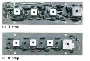
Used in the vital FM tuner IF strip, Scott Integrated Circuits actually incorporate more circuitry in less space. The new Scott IF strip now contains 20 transistors, as compared to four in the previous model.
Scott's previous IF strip, without IC's, gave superb old strip IC IF strip FREE capture ratio and selectivity figures of 2.5 dB and 45 dB, respectively. Scott's new Integrated Circuit IF strip is conservatively rated at 1.8 dB capture ratio and 46 dB selectivity. Independent test reports, however, show the new Scott Integrated Circuits to be consistently capable of an incredible 0.8 dB capture ratio! What Scott IC's mean to you.
Now you can hear more stations with less noise and interference. Weak, distant stations that you never have been able to receive before will suddenly appear with amazing clarity. Outside interference from electric razors, auto ignitions, etc., will be drastically reduced. And, you can count on enjoying this amazing performance for many, many years ...thanks to the absolute reliability of Scott Integrated Circuits.
When will Scott IC components be available? Scott IC receivers are now at your Scott dealer's showroom. Scott IC's are incorporated into the design of the 388 120-Watt AM/ FM stereo receiver, the 348 120-Watt FM stereo receiver, the 344 85-Watt FM stereo receiver, and the 342 65-Watt FM stereo receiver. Your Scott dealer will be glad to demonstrate to you the amazing capabilities of these new receivers.
Scott ... where innovation is a tradition
H. H. Scott, Inc., Dept. 35-03, 111 Powdermill Road, Maynard, Mass. Export: Scott International, Maynard, Mass.
Fact-filled, fully illustrated booklet on Scott Integrated Circuits ... simply circle Reader Service No. 100. Another innovation from Scott, manufacturers of superb components, compacts, kits, speakers, and consoles.
+++++++++++++++
Number 42 in o series of discussions by Electro-Voice Engineers
CARDIOID IS NOT ENOUGH
ROBERT F. HERROLD, III
Microphone Project Engineer It is frequently assumed that a unidirectional microphone exhibiting a perfect cardioid pattern is ideal for reducing unwanted noise pickup. While there is an element of truth in this assumption, normal studio practices usually dictate that a microphone with a polar pattern that deviates from the classic cardioid shape is more effective.
During development of the new Electro Voice Model RE-15 Super Cardioid, it was determined that a cardioid microphone with optimum rejection at 180° off axis could maintain this rejection only within a cone of about 15° to 20°. This meant that the microphone had to be aimed directly away from the offending noise for maximum effectiveness.
The design of the RE-15 was altered to permit a small lobe to exist at 180° (still providing at least 15 dB of cancellation). This placed the point of maximum rejection at 150° off axis, and increased the useful cone of rejection to about 80°. Since typical placement of any microphone on floor stands and booms does not permit maintaining the noise to be rejected exactly and consistently at 180° off axis, this increased area of rejection adds greatly to the usefulness of the microphone.
The Model RE-15 design is a blend of the concept* used in the Model 666 Variable D® microphone and the Model 676 Continuously Variable –D models. In essence, fixed cancellation ports are provided close to the diaphragm for frequencies above 1000 Hz, while a slotted line provides a variable distance port for cancellation of frequencies below 1000 Hz.
As a result of this design the RE-15 offers unusually uniform frequency response at all points of the polar pattern within its useful frequency range. Frequency response at 90° and 180° off axis is within ±2 dB of on-axis response. Thus there is no change in sound character as a performer moves off axis-just a change in sound level.
The RE-15 design also eliminates the polar pattern variations at different frequencies that are typical of single-D designs, as well as the proximity effect common to most cardioid microphones.
The Super Cardioid pattern, plus the uniformity of response has been extensively field tested, and proved more effective than the classic cardioid in the majority of studio conditions.
SETTING NEW STANDARDS IN SOUND
For technical data on E-V products, write: ELECTRO-VOICE, INC., Dept. 373A 602 Cecil St., Buchanan, Michigan 49107
+++++++++++++++++++++
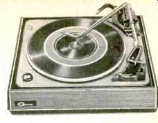
GARARD'S 50 MARK II
A NEW COMPACT AUTOMATIC TURNTABLE WITH HIGH PERFORMANCE FEATURES AT ONLY $54.50 Far from being keyed to the level of budget or even medium priced music systems, the 50 Mark II deserves comparison with the finest and most expensive automatic turntables. Its dramatic impact begins with styling ... functional, handsome and beautifully coordinated. Operating features are equally impressive ... encompassing the latest advances in convenience and performance. The 50 Mark II is one of five new Garrard Automatic Turntables.
For complimentary Comparator Guide describing each model, write: Dept. 4C-1, Garrard, Westbury, N. Y. 11590. New coordinates! Garrard base, richly molded in ebony, t walnut overlay.
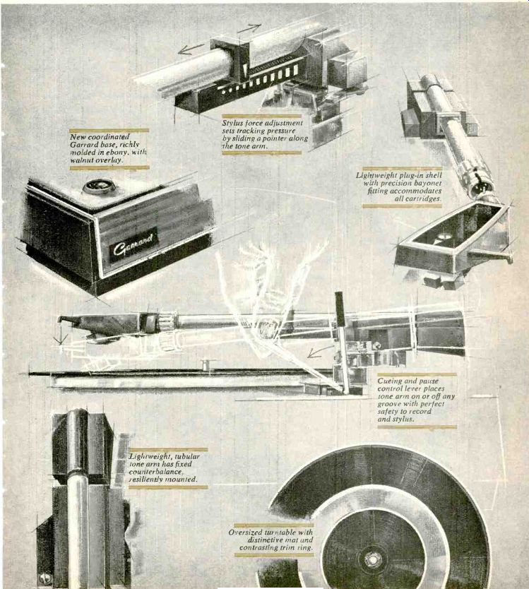
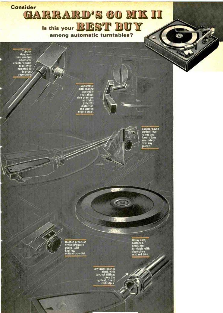
... tone arm has adjustable (counterweight, resiliently mounted to prevent resonance,
Is this your
among automatic turntables? Automate anti-skating assembly neutralizes side pressure on styles ...prevents distortion and uneven record wear.
Built-in precision stylus pressure gauge, with knurled', optical-type dial.
Low mass plug-in shell, with bayonet fitting; takes the lightest, finest cartridges.
Cueing/pause control lever raises and lowers tone arm safely over any groove.
Heavy cast, balanced, oversized turntable with decorative mat and trim.
CONSIDER FEATURES Cueing and pause control. Automatic anti skating assembly. Cast oversized turntable.
Adjustable counterbalanced tone arm.
Precision stylus pressure gauge.
Shielded Laboratory Series motor and other Garrard innovations built into this excellent unit.
CONSIDER PERFORMANCE Tracking as low as V2 gram. Wow, flutter, rumble, and speed accuracy surpassing NAB standards.
CONSIDER VALUE . . only $74.50 less base and cartridge Built to unsurpassed standards...this very successful compact unit, bearing the Garrard name, is a source of utmost satisfaction and continuing pride in any music system.
For complimentary Comparator Guide describing all five new Garrard automatics, write Garrard, Dept. AC-1, Westbury, N.Y. 11590. Two interchange-+¡ able spindles for sure, safe, gentle handling of records (a) short-for single record play (b) long-for intermix automatic play when desired.
-------- Mark of the leader
The ultimate expression of over 50 years of Garrard leadership, this much-imitated but unequaled automatic transcription turntable contains many developments invented, perfected and brilliantly refined by the Garrard Laboratories, and now considered essential for the finest record reproduction.
Heavy, cast 12" anti-magnetic turntable is dynamically balanced with copper weights on underside.
Patented anti skating control, calibrated in half gram markings, is adjusted with springless, sliding weight.
Anti-static, dust repellent turntable mat has safety rings at 12", 10" and 7" positions to protect stylus should automatic switch be activated without record on turntable.
Two interchangeable spindles: short spindle facilitates manual play; long, center-drop spindle handles eight records fully automatically.
Hydraulic cueing and pause control eliminates damage to records or stylus through manual handling.
Low mass cutaway shell compatible with the most advanced, lightest tracking cartridges.
Dynamically balanced, counter-weight adjusted tone arm of Afrormosia wood and aluminum for light weight, low resonance.
Built-in stylus pressure gauge, calibrated in quarter gram intervals, has click-stops for precise, audible/ visible settings.
Just two years ago, the stereo high fidelity world was introduced to the Lab 80, the first Automatic Transcription Turntable. It was instantly acclaimed because of the significant developments it contained. These imparted professional performance capabilities never before anticipated in automatic record playing units. Now, the Garrard Laboratories have refined and surpassed the original model with the Lab 80 Mark II, still priced at only $99.50, less base and cartridge. It is one of five new Garrard Automatic Turntables each of them the leader in its class.
For complimentary Comparator Guide, write Garrard, Dept. AC-1, Westbury, N.Y. 11590.
+++++++++++++++++++
Dynaco
UNCOMPROMISED QUALITY
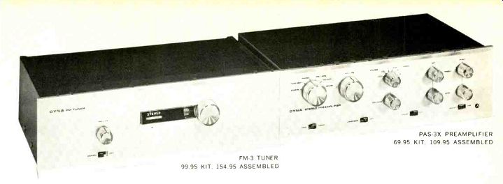
FM-3 TUNER, 99.95 KIT, 154.95
This combination of PAS-3X preamplifier, FM-3 tuner, and Stereo 120 amplifier represents the highest level of quality which can be attained with high fidelity components. It combines the virtues of both tubes and transistors in a flexible modular system without skimping to squeeze it into one unit.
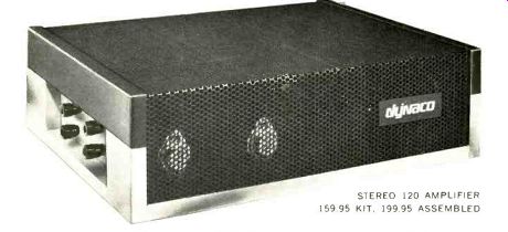
Two of these components have passed the test of time years of increasing public acceptance. The Stereo 120 is an all new design. All have been engineered and produced with the same underlying Dynaco philosophy of offering superlative performance at the lowest possible cost-when you buy it, and as long as you own it. Everyone recognizes that Dynaco is "best for the money." We know that it should be judged regardless of price-Dynaco quality has never been compromised by cost considerations.
PAS-3X PREAMPLIFIER 69.95 KIT, 109.95 ASSEMBLED ISEO QUALITY
Our sole concern is sonic perfection. We don't follow the herd in engineering, styling or promotion. Fads, status and "revolutionary new sounds" never enter our planning. We avoid regular model changes and the planned obsolescence they engender. We take the extra time to do things right the first time. That probably explains why our limited product line has become increasingly popular each year. It's why our kits are so easy to build; why maintenance is so easy; and service problems so few. We constantly strive to improve our products though, and when we do, these changes are available to our customers to update existing equipment at low cost.
Our detailed literature, available on request, gives the full specifications which help to explain why the Dynaco components illustrated (PAS-3X, FM-3 and Stereo 120) will provide the finest sound possible. Specifications are important, but the most complete specifications cannot define truly superb sound. Go to your dealer, and compare Dynaco with the most expensive alternatives, using the very best speakers and source material you can find. Be just as critical, within their power limitations, of our best-selling Stereo 70, Stereo 35 and SCA-35.
Of course, if you are now a Dyna owner, don't expect us to convince you to replace what you already have.
But your friends might benefit!
STEREO 120 AMPLIFIER 159.95 KIT, 199.95 ASSEMBLED
Dynaco. 3912 Powelton Ave. Philadelphia, Pa. 19104, U.S.A.
++++++++++++++++++++
The man with the golden ear 17 1/2 cubic feet of sound in your living room requires two basic essentials. The first is a Golden Ear to catch every nuance. The second, rather obviously, is a permissive wife. Some men have both (unbelievably) and have installed the actual Altec A7 "Voice of the Theatre" in their living rooms. This is the same system that has become standard for recording studios, concert halls and theatres.
However, if your wife is something less than permissive, Altec has the answer.
We have taken all A7 speaker components and put them in a single package.
Half the size. The same high-frequency driver. The same cast aluminum sectoral horn. The same 15" low frequency speaker.
The same crossover network. Frequency response is unbelievably wide ( beyond the range of human hearing, if that's of any interest). The midranges are "in person" and that's where 90% of the sound is. Basses don't growl and groan.
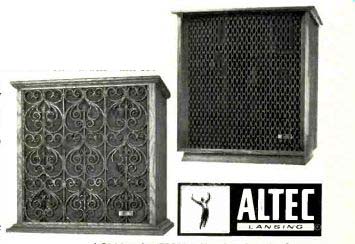
Trebles don't squeal. Styling? The hand-rubbed walnut Valencia has a delicately curved wood fretwork grille. The oak Flamenco is pure Spanish. Send for your '67 Altec catalog or pick one up from your dealer. Compare. Buy. If the wife complains, tell her about your Golden Ear.
A Division of , Yir C Ling Altec, Inc., Anaheim, California
SPECIFICATIONS--FREQUENCY RESPONSE: 35-22,000 Hz; IMPEDANCE: 8/16 ohms; CROSSOVER FREQUENCY: 800 Hz; DIMENSIONS: 29%" H. x 27W' W. x 19" D. (Flamenco is two inches lower); COMPONENTS: 416A 15" low-frequency speaker with a frequency response of 20-1600 Hz and a cone resonance of 25 Hz; 806A high-frequency driver; 811 B high frequency sectoral horn with 90° horizontal and 40° vertical distribution; N800G dividing network with continuously variable HF shelving attenuation.
PRICE: 846A Valencia, $333; 848A Flamenco, $345.
++++++++++++++
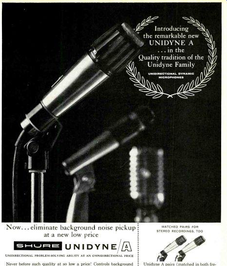
Now... eliminate background noise pickup at a new low price UNIDYNE/ UNIDIRECTIONAL PROBLEM-SOLVING ABILITY AT AN OMNIDIRECTIONAL PRICE Never before such quality at so low a price! Controls background noise confusion, "thumping" sound from percussion instruments, and "hollow" sound associated with omnidirectional microphones.
You'll be amazed and impressed by the clear, life-like tapes you can make with the new Shure Unidyne A ... a low-cost, fine quality, wide-response unidirectional microphone with a truly symmetrical pickup pattern that picks up sound from the front only, at all frequencies. Only $35.40 net.
SEND FOR LITERATURE: SHURE BROTHERS, INC. 222 HARTREY AVENUE, EVANSTON, ILL. MATCHED PAIRS FOR STEREO RECORDINGS, TOO
Unidyne A pairs (matched in both frequency and output) detect the subtle differences that "localize" sound for realistic, spatially-correct stereo tapes.
Only $70.80 net for the factory-matched pair, complete with plugs attached.
(Note: The famed Unidyne II & III are also available in matched pairs).
SHURE MICROPHONES WORLD STANDARD WHEREVER SOUND PERFORMANCE AND RELIABILITY ARE PARAMOUNT
+++++++++++++
When you've got a reputation as a leader in transistor technology, you don't introduce a transistor amplifier that is like someone else's. We didn't. The new Sony TA-1120 integrated stereo amplifier is the case in point. We considered the few remaining shortcomings that have kept today's transistor amplifiers from achieving the quality of performance of the best tube amplifiers and set out to solve them. To do it, we even had to invent new types of transistors. The result: the first truly great solid-state stereo amplifier.
Distortion is lower than in the finest tube amplifiers at all frequencies and power levels.
Signal-to-noise ratio: better than 110 db.
Damping factor is extraordinarily high (140 at 16 ohms). Frequency response: practically flat from 10 to 100,000 HZ (+0 db/-1 db). Plenty of power, too (120 watts IHF at 8 ohms, both channels). With an amplifier as good as this, the preamp section has a great deal to live up to. It does, magnificently! Solid-state silicon circuitry throughout coupled with an ingenious design achieve the lowest possible distortion. Sensible arrangement of front panel controls offers the greatest versatility and ease of operation with any program source.
Finally, to protect your investment in this superb instrument, an advanced SCR (silicon-controlled rectifier) circuit prevents possible damage to the power transistors due to accidental shorting of the outputs.
The Sony TA-1120 stereo amplifier/preamp at $399.50 and the TA-3120 stereo power amplifier, $249.50 are available at a select group of high fidelity specialists who love and cherish them. And will get as much enjoyment out of demonstrating them as you will from their performance. So visit your dedicated Sony high fidelity dealer and enjoy. Prices suggested list. Sony Corporation of America Dept. H 47-47 Van Dam St. L.I.C., N.Y. 11101.
With so many fine amplifiers our first had to be something special.
It is!
Sony
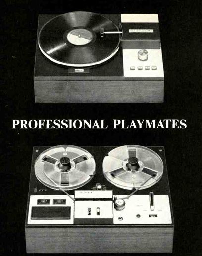
The new Sony Solid State 350 adds professional performance to home entertainment systems Selecting the brilliant new Sony Solid State 350 to fulfill the stereo tape recording and playback functions of your professional component music system will also enduringly compliment your impeccable taste and passion for music at its finest. With an instant connection to your other stereo components, the versatile two-speed Sony 350 places at your pleasure a full array of professional features, including: 3 heads for tape and source monitoring. Vertical or horizontal operation. Belt-free, true capstan drive. Stereo recording amplifiers and playback pre-amps. Dual V U meters. Automatic sentinel switch.
Frequency response 50-15,000 cps-{2db. S.N. ratio plus 50db. Flutter and wow under 0.15%. Richly handsome gold and black decor with luxurious walnut grained low profile base. This remarkable instrument is yours at the equally remarkable price of less than
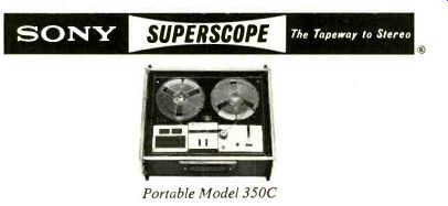
$199.50. Should you want to add portability to all this, there's the Model 350C, mounted in handsome dark gray and satin-chrome carrying case, at less than
$219.50, For information write Superscope, Inc.. Sun Palley, Calif.
SONY SUPERSCOPE--The Tapeway to Stereo Portable Model 350C
-----
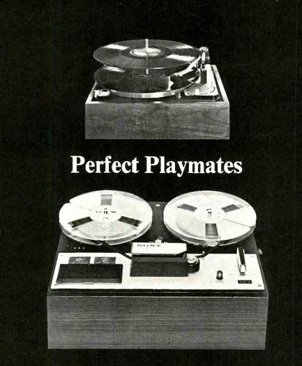
Sony adds an exciting new dimension to home entertainment for less than $14950 Now, from World-famous Sony, the perfect playmate for your record player-the new Sony model 250 solid state stereo tape recorder. With a simple, instant connection to your record player you add the amazing versatility of four track stereo recording and playback to complete your home entertainment center and create your own tapes from records, AM or FM Stereo receivers, or live from microphones-61/4 hours of listening pleasure on one tape ! This beautiful instrument is handsomely mounted in a low-profile walnut cabinet, complete with built-in stereo recording amplifiers and playback pre-amps, dual V.U. meters, automatic sentinel switch and all the other superb features you can always expect with a Sony. All the best from Sony f or less than $149.50. Send today for our informative booklet on Sony PR-150, a sensational new development in magnetic recording tape. Write: Sony/Superscope, Magnetic Tape, Sun Valley, California.
For literature or name of nearest dealer write to Superacope, Inc., Dept. 17. Sun Valley, Catifornia.
SONY SUPERSCOPE--The Tapeway to Stereo
++++++++++++++++
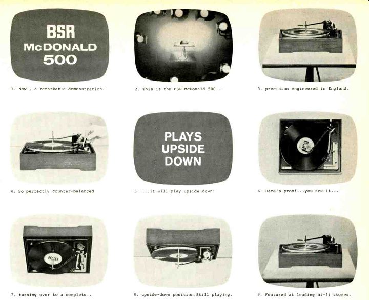
1. Now...a remarkable demonstration.
4. So perfectly counter-balanced
7. turning over to a complete...
2. This is the BSR McDonald 50C ... PLAYS UPSIDE DOWN
5. ...it will play upside down!
8. upside-down position. Still playing.
3. precision engineered in England.
6. Here's proof...you see it...
9. Featured at leading hi-fi stores.
Did you catch this amazing act on the Johnny Carson "Tonight" Show? This almost unbelievable demonstration of the tracking ability of the BSR McDonald 500 automatic turntable is being telecast on the popular NBC-TV Johnny Carson "Tonight" Show as well as the "Today" Show starring Hugh Downs. It demonstrates the BSR precision engineered automatic turntable doing a complete 180° turn ... while it continues to play a record perfectly even when it reaches the completely upside-down position! (The secret is the tone arm that is perfectly counter-balanced horizontally and vertically!) See this remarkable automatic turntable and see its many other unique features. Write for free literature.
McDONALD. 500 Precision crafted in Great Britain BSR (USA) Ltd., Blauvelt, N.Y. 10913
++++++++++++++++++++++
Some plain talk from Kodak about tape:
Uniform magnetic sensitivity (or the lack thereof)
Uniformity for a tape is like kissing babies for a politician. Without it, you're hardly in the running. We take uniformity in all of tape's characteristics very seriously at Kodak. Maybe it's all those years of putting silver emulsions on film that's made us so dedicated to the idea. Uniformity in terms of magnetic sensitivity is one of the most important measures of a tape's performance. Non-uniformity can result in all sorts of bad things like level shifts, instantaneous dropouts, periodic non-uniformity, output variations, distortion, and variations from strip to strip.
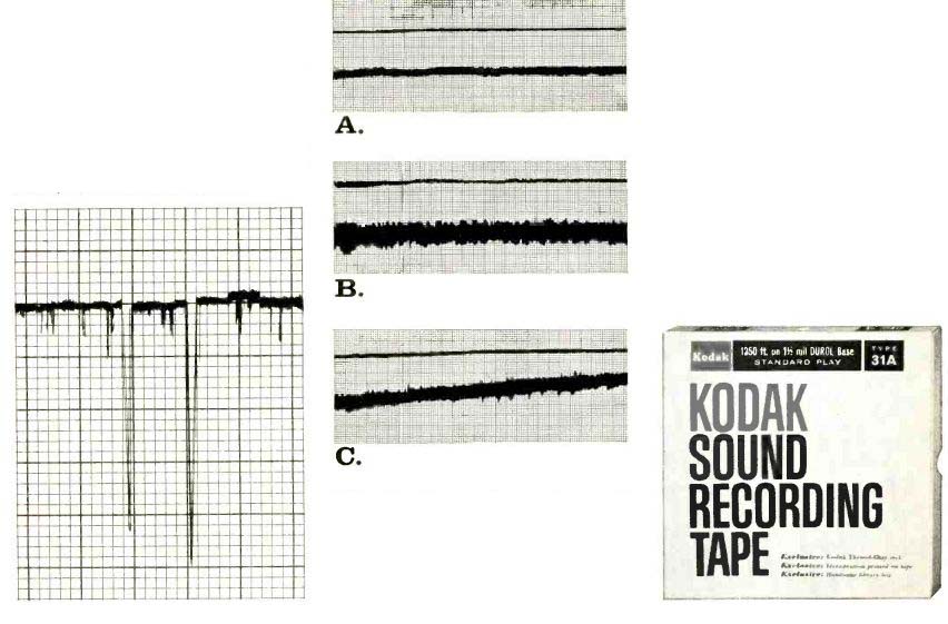
Testing for all these possible flaws on a tape is a simple procedure in the lab. Standard industry practice is to record a long wavelength signal (37.5 mil) at a constant input level. The signal from the playback amplifier is then filtered and the output at particular critical wavelengths is permanently charted by a high-speed pen recorder which registers variations on a chart.
Instantaneous dropouts caused by foreign matter on the tape surface, for example, would look like this:
The long and the short of it:
The low frequency procedure gives a good picture of variations in oxide thickness. We take it one step further ... also test for short wavelength-1.0 mil. This helps evaluate surface smoothness and tape-to-head contact.
Taken together, they aid in evaluating the level of lubrication, slitting, and oxide binder characteristics. The smoother the lines, the more uniform the magnetic sensitivity. Guess which graph below is KODAK Sound Recording Tape (the other two graphs represent quite reputable brands of other manufacture) :
What looks good sounds good.
Congratulations if you picked brand A, Kodak tape. It is notably more uniform
...doesn't vary more than 1/4 db within the reel ... no more than 1/ db from reel to reel.
You benefit as follows:
1. Within-reel uniformity.
(a) Less instantaneous and short term amplitude modulation of the signal, which results in a cleaner signal on playback.
(b) Reduced drift gives less variation in frequency response.
(c) Better uniformity across the strip width (no lengthwise coating lines) results in a more nearly balanced output for stereo recordings.
2. Reel-to-reel uniformity.
(a) Better coating uniformity gives a more uniform low-frequency sensitivity. This allows splicing of sections of tape from one reel with tape from other reels without obvious signal level changes.
(b) Better coating uniformity also results in a minimum change in optimum bias which allows the professional to establish an operating bias nearer the optimum bias.
KODAK Sound Recording Tapes are available at most camera, department, and electronic stores. New 24-page comprehensive "Plain Talk" booklet covers all the important aspects of tape performance, and is free on request. Write: Department 940, Eastman Kodak Company, Rochester, N.Y. 14650.
KODAK SOUND RECORDING
+++++++++++++
Also see: