MANUFACTURER'S SPECIFICATIONS
Power Output: 200 watts per channel, both channels driven into 8-ohm loads at any frequency from 20 to 20,000 Hz with less than 0.25% total harmonic distortion; 300 watts per channel at 4 ohms; 100 watts per channel at 16 ohms, 600 watts at 8 ohms, monophonically.
Intermodulation Distortion: Less than 0.1% at rated output for any combination of frequencies between 20 and 20,000 Hz.
Frequency Response: 20 to 20,000 Hz ±0.5 dB at rated output.
Input Impedance: 50 K ohms.
Input Sensitivity: 1.6 volts.
Hum and Noise: 100 dB below full output, 20 to 20,000 Hz.
Damping Factor: More than 80 up to 1 kHz, 8 ohms; more than 30 up to 10 kHz.
Dimensions: 17 in. W. x 14 in D. x 7 in H.
Weight: 52 lbs. net.
Power Consumption: 11 amps maximum.
Price: Factory wired, $669.00; with meters, $769.00; as kit, $499.00; meter kit $85.00.
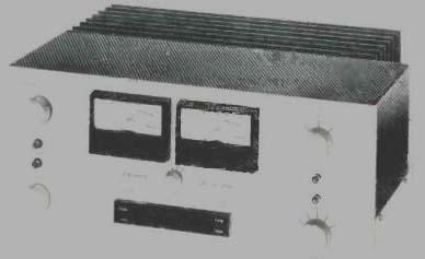
The Dynaco stereo 400 is a rugged, solidly-built 200-watts per-channel power amplifier. The units reviewed were one wired by the factory with MC-4 optional meter and a kit, built but not measured. Most of the circuitry is on printed boards with considerable hard wiring interconnecting the various boards, front-panel controls, and output transistors.
The heat sink on this amplifier is very large and quite effective; it is made of eight 1/8-in. thick, black-anodized, extruded aluminum fins.
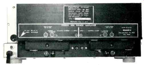
Fig. 1--Rear panel of amplifier.
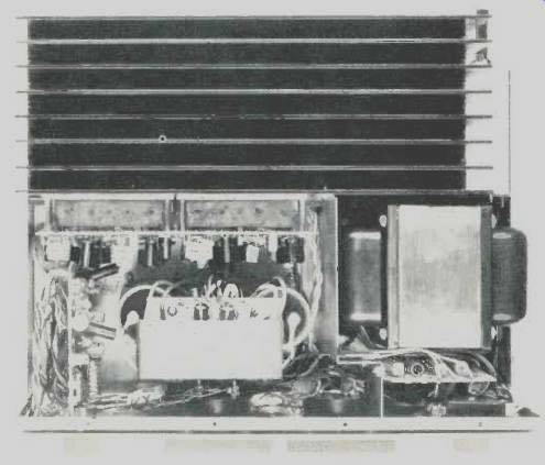
Fig. 2--Interior view.
Front-panel controls consist of two input-gain controls, high- and low-cut filter switches, a four-position meter-sensitivity switch, a five-position Dynaguard control switch, and a three-position (On/Off/On) phase-reversing power switch. Also on the front panel are the two output meters, two speaker fuses, and Dynaguard indicator, overtemperature and pilot lamps. The back panel has RCA input jacks and a pair of dual binding posts for the speaker connections.
While usefully large, the output meters on this amplifier might have been more attractive if they were flush mounted and a bit further apart as on some other amps. I have to admit this is a matter of taste. The zero dB power markings for this meter system are 156, 78, 20, and 5 watts into 8 ohms.
The ranging and marking system this reviewer would have preferred to see is a watts scale, with rated power into 8 ohms marked zero dB, and a range switch which changes meter deflection in 10 dB steps, i.e. full power, 10% of full power, 1% of full power, etc. With this scheme, no conversion of relative dB to power is required.
Circuit Description
Figure 3 shows a block diagram of the main power amplifier section of the Dynaco 400. The differential input amplifier shown in the diagram is preceded by a gain-of-one isolation amplifier, whose purpose is to lightly load the 100 K input level control and provide a low output impedance to drive the high- and low-cut filters and the Dynaguard output-power limiter. The filters are two-section passive RC types and provide ultimate attenuation of 12 dB per octave with normal cutoff frequencies of 50 Hz and 15 kHz. Q1 and Q2 form a differential input pair fed by constant-current source Q3. The push-pull (differential) output of Q1 and Q2 is fed into the input of the second differential amplifier, Q4 and Q5. The output of Q5 has the proper phase to drive the output stage, which is effectively a complementary emitter follower.
The usual practice at the pre-driver point in a power amp would be to have a bootstrapped resistive collector load for the pre-driver, or a transistor current source. Neither of these options uses the opposite-phased signal which is available at the collector of Q4 which would be tied to signal ground. The 400 uses this signal phase, coupling it through a common-base voltage-translator stage, Q6, up to the base of Q7, a common-emitter inverting stage. The collector of Q7 is connected down through the bias regulator to the collector of the predriver, Q5. This accomplishes two desirable objectives. The first is that both push-pull signal phases have been combined in a differential input to the single-ended output predriver circuit. Even harmonics generated in the first and second differential stages tend to cancel in the combined output. The second feature of the circuit is that the output of the predriver can drive the output stage equally hard in both directions. The disadvantage of this scheme is that the signal from the collector of Q4 has to pass through two more potentially distorting devices before it combines with the output of Q5.
The bias regulator circuit, consisting of Q8 and Q9, provides a temperature-compensated voltage difference between the two input drive lines to the output stage. It is a two-stage-shunt voltage regulator instead of the more usual single transistor or diode circuit.
The output stage is effectively a complementary emitter follower with complementary emitter-follower drive. The composite NPN and PNP output and driver devices are made up of two series-connected transistors to increase the safe operating area. The upper driver bases of Q12 and Q15 are driven off voltage dividers from the amplifier output buss up to the respective supplies, plus and minus, for Q12 and Q15 respectively. The action of these dividers causes the instantaneous voltage across the series pairs to be divided about equally between the series devices. Overall negative feedback is applied from the output to the inverting input of the input stage, the base of Q2.
Dynamic voltage/current limiting is accomplished by shunting the output stage drive lines to the output buss through limiting transistors Q10 and Q11. Both voltage and current of the output stage are sensed and applied to the bases of these limiter transistors.
This amplifier has, in addition to dynamic protection of the output stage, a number of other protective circuits that protect both the load and the amplifier. These include fuses in the amplifier output lines, fuses in the B+ supply lines in both channels, the input high- and low-cut filters which keep excessive subsonic and supersonic energy from entering the amplifier (when switched in), a time-delay and output d.c.-detection circuit, and the Dynaguard power-output limiter circuit.
The time-delay and d.c. detector circuit provides a turn on time delay which keeps the speaker relay open long enough to prevent turn-on thumps. If the output line of either channel exceeds a nominal plus or minus 1 1/2 volt d.c., a comparator circuit that senses the output line d.c. level will open the speaker relay and thus protect the speaker from potentially destructive d.c. voltages.
The Dynaguard power limiter circuit operates by reducing the instantaneous peak value of the input signal to the power amplifier. Limiting action commences after a time delay that depends on how much greater the output signal is than the power limit selected. The greater the output power compared to the selected power limit, the shorter the time delay before limiting commences. This delay allows short signal transients to pass unaltered up to the clipping power of the amp while holding the average continuous power to the preselected value or less. The front-panel control switch has five positions: Off, 120,80,40 and 20 watts. When limiting takes place, front-panel indicators (located between the speaker fuses) light up.
The power supply consists of a large power transformer, bridge rectifier, and two 10,000 µF, 80 V capacitors. The ±75 V d.c. developed for the power amp is reduced by Zener regulators to +13 volts for the Dynaguard circuit and the input buffer amp.
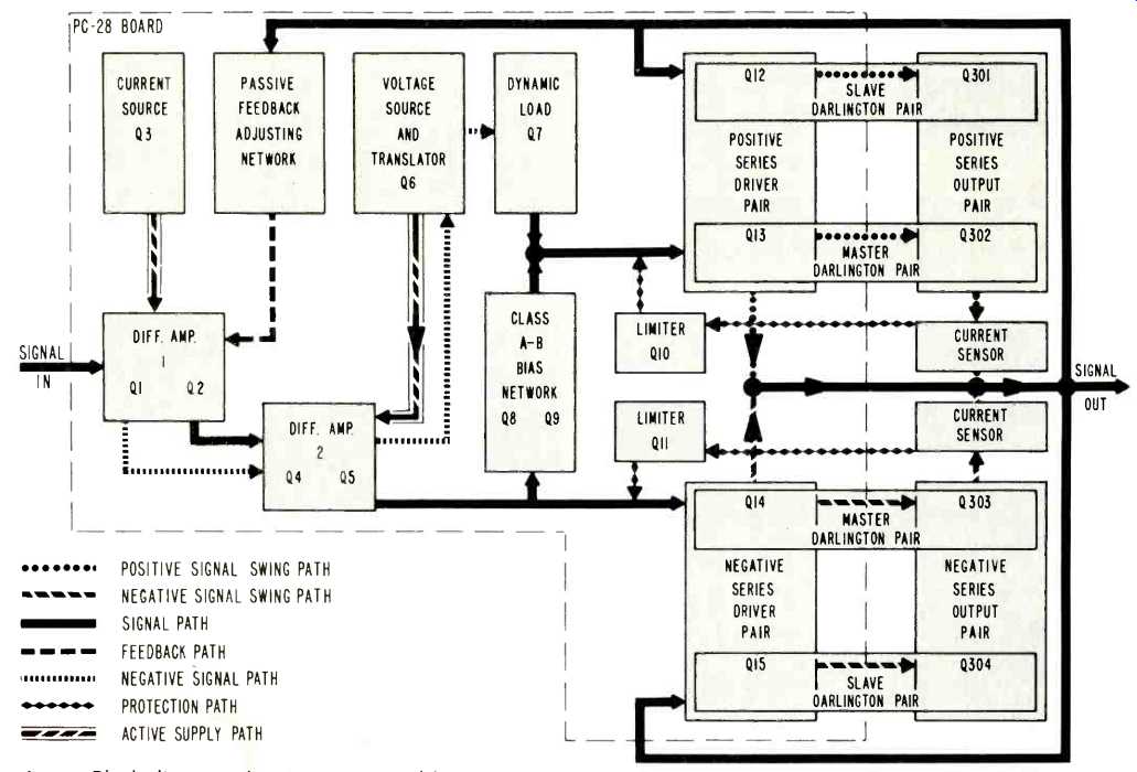
Fig. 3--Block diagram of main power amplifier section.
Kit Builder's Note
Since I'd previously put together a number of kits, I was not surprised to see how thoroughly the manual detailed assembly and wiring, theory of operation, tests prior to plug-in, and tests and checks for qualified technicians. The 40-page manual even included a quick course on soldering, though I wouldn't recommend anyone put this kit together until he'd assembled at least one somewhat simpler project. I'd also recommend that anyone who's not good at soldering, practice soldering several wires compactly to a lug before attempting that job in this kit. The company supplies a 2-x-3-ft. pictorial diagram printed in five colors, showing exactly where every wire and part goes.
About 99% of the small components (resistors, capacitors, transistors, and integrated circuits) were already mounted on the four printed circuit boards. The only major parts not so mounted were the very heavy power transformer, two 10,000 µF power supply capacitors, the protective relay, big circuit breaker, a.c. power switch, input gain controls, and attenuator switches, plus the rear terminal panel, the gold-finished front panel, black perforated metal cover, and the massive heat sink (the biggest in the business, Dynaco says) for the power output transistors.
Altogether there were 14 pages of instructions, and the total number of wiring and assembly steps were 212. Conveniently broken down into some five sections, each took three to four hours. Total time, not counting the hour or so of familiarization nor troubleshooting time at the end, was 19 hours. Someone less at home with a soldering iron would take longer.
The actual assembly and wiring went rather smoothly, in great part because the pictorial diagram is so clear that one could almost put the kit together just using that. Working from the step-by-step instructions, and referring each time to the pictorial diagram, made it quite straightforward.
The only tools needed were a pair of diagonal cutters for cutting and stripping the wires, a pair of long-nose pliers for reaching into close quarters, a medium-sized screwdriver, and a soldering iron. Dynaco supplied solder and six hanks of different colored wire.
When I'd completed the assembly and wiring I went through the preliminary tests Dynaco includes. I found that I had a dead short in one channel. Quickly consulting the instructions In Case of Difficulty-(what to do for) Failure In Preliminary Tests, I found I had one diode wired in backwards (not the cause of the short) and a splash of solder which was shorting part of one PC board to one ground terminal. Correcting these errors enabled the amplifier to pass the preliminary test steps, and connecting up the other components, I had sound! How does it sound-awesome...
Summing up, this is a project most people could successfully accomplish, much like other Dynaco or Heath kits. I would recommend it only to those who have put together at least one other kit previously and who can be extremely careful :n following the instructions to the letter (this applies to all electronic kits). There is nothing esoteric about the assembly or the wiring, even though the circuit is quite sophisticated and the unit physically big, and heavy (52 lbs, net). -C.G.
Listening Tests
The Dynaco 400 was compared aurally to a number of other fine solid-state amplifiers. Cartridges used for record listening were a Supex SG-900 and a Fidelity Research FR-1 Mk Il going through a tube-type phono preamp, specially made by the reviewer, which has the extra gain needed for use with low-output moving-coil pickups.
Overall, the sound of the 400 is as good or better than most of the 150to 300-watts/channel amps available, though at times some of the other amps were able to score points in handling certain sorts of difficult material. Bass was tight and defined and generally was at least as good that produced by these other amps. The midrange and high end were quite good, though the amp was judged at times to have a bit of graininess and edginess and thus not as sweet and clean as might be desired.
Editor's Note: Dynaco informs us that a very recent change in the value of the resistor R305 to 1.8 ohms reducing the Q of the output inductor-resistor combination effects an improvement in high-end sound quality. This is easily made on existing Stereo 400s by adding a 2.2 ohm resistor (2 W. min.) in parallel with each output inductor (choke coil assembly) on top of the relay mounting plate. This will also noticeably improve the square wave trace into a capacitive load, especially at low drive levels.
Measurements
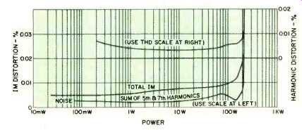
Fig. 4--Harmonic and intermodulation distortion vs. power output, 1 kHz,
8 ohms.
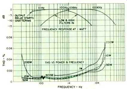
Fig. 5--Frequency response (top) at one watt, with filters in and out (note
that spectrum from 100 Hz to 10 kHz is omitted). Lower curves show distortion
vs. power and frequency.
IM distortion and THD at 1 kHz versus power output are shown in Fig. 4. Both THD and IM are satisfactorily low. THD versus frequency and power is shown in Fig. 5. The ripples in the curves near 120 Hz are due to a small amount of beating between the signal frequency and 120 Hz harmonic of the power supply. Also shown in Fig. 5 is the one-watt frequency response. This was not measured below 5 Hz as the speaker relay started to chatter at about 5 Hz because these low frequencies begin to appear as d.c. to the comparator circuit which controls the output relay.
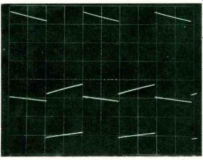
Fig. 6--10-volt (p-p), 50-Hz square wave output, 8-ohm load. Top shown at
20 V/cm; bottom, 5 V/cm.
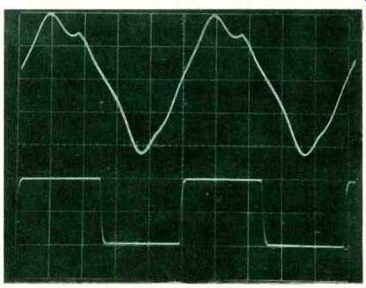
Fig. 7--10-volt, 20-kHz square wave output, 1µF load (top). 10-kHz output,
8-ohm load (bottom).
The first test run on the Dynaco 400 was the FTC power test, running at 1/3 rated power with a 1 kHz test signal for one hour. This test was passed with flying colors and is a tribute to the excellent heat-sink design of the 400. Voltage gain into a 8-ohm load was measured and found to be 26X, or 28.3 dB, with the input controls set at maximum.

Table I-Output Noise (microvolts)

Table II-Dynaguard Limiting (watts)
'Scope photos of the amplifier response with different frequencies and loads are shown in Figs 6 through 9. 50 Hz and 10 kHz square waves with 8-ohm loads at 10 V p-p are good, generally about the same as other top-rated amplifiers we've tested. The 10-kHz, 10-V square wave with a 2µF capacitive load is typical of most solid-state power amps with LR output buffer networks.
The large signal 50-Hz and 20-kHz square waves into 8 ohm loads are excellent. In particular, the symmetry of the 20-kHz response is an excellent commentary on the use of the differential input to single-ended converter predriver stage. The large signal response with capacitive loads isn't as good, as evidenced by the somewhat slower slew rate on the 10and 20-kHz square waves with 2 and 1µF loads. The 400 was not able to deliver a full 200 VA and 20 kHz and at slightly over 100 VA exhibited about 1 percent THD.
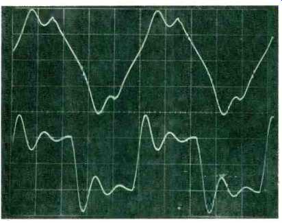
Fig. 8--10-volt, 10-kHz output, 2µF load. V/cm.; bottom, 5 V/cm. Top shown
at 20
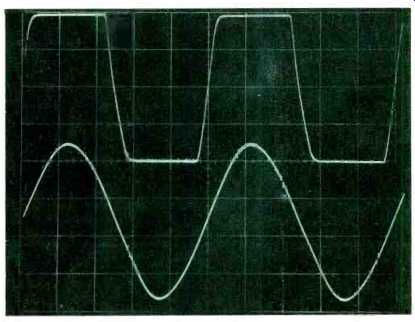
Fig. 9--10-volt, 20-kHz output, 8-ohm load (top). 3C-volt, 20-kHz output,
1µF load; 1% THD (bottom).
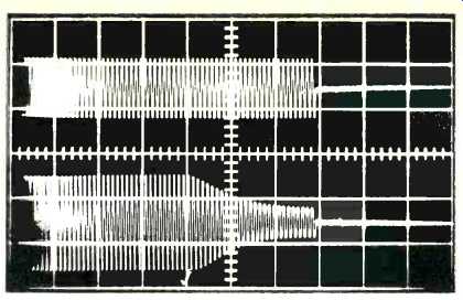
Fig. 10-Input (top) and output (bottom) 90 Hz signal, 100 watt output level,
showing Dynaguard action at 20 position. Total time, 1 second.
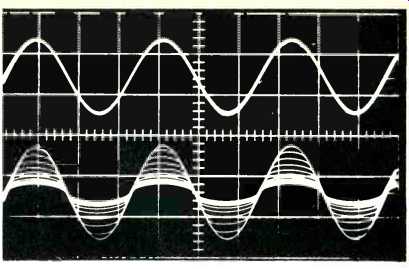
Fig. 11--Input (top) 150 Hz signal. Bottom traces show progressively smaller
output as Dynaguard at 20 setting reduces output from full 200 watts to
one-fifth that level.
Output noise as a function of measurement bandwidth is shown in Table I, with both high and low filters in and out.
Damping factor was slightly greater than 80 from 20 Hz to 1 kHz, decreasing smoothly to 33 at 10 kHz and 19 at 20 kHz.
Power output at on-set of clipping into 4-, 8-, and 16-ohm loads was 324, 221, and 132 watts, respectively.
The performance of the Dynaguard limiter was checked by noting the steady-state power that just sustained limiting and the steady-state power that caused the front-panel indicators to light, both as a function of power levels indicated on the front panel. In general, the power for maintenance of limiting was lower than that which caused the indicators to light and both were somewhat lower than the levels indicated on the front panel. Since the right channel's adjustments were off a bit, so that its limited power was somewhat lower than the left channel's, measurements for the left channel only for 8-ohm loads are shown in Table II.
'Scope photos from the Dynaco manual, indicating some of the dynamics of the Dynaguard limiting action, are shown in Figs. 10 and 11.
To sum up, the Dynaco 400 is another good performer in the 200-watts-per-channel class. Its overall sound is good, and its protective features make it difficult, if not impossible, for someone to blow this amp or a speaker connected to it. Considering the 400's price and performance, particularly when purchased as a kit, this unit represents good value. If one desires an amp in this power class, the Dynaco 400's performance and features should be considered.
--Bascom H. King
(adapted from Audio magazine, May 1975)
Also see:
Dynaco SCA-80Q Amplifier (Equip. Profile, Jul. 1972)
Dynaco PAT-5 Preamplifier (Equip. Profile, Feb. 1976)
Dynaco AF-6 AM/FM Tuner (Equip. Profile, Sept. 1974)
Dynaco A-25XL Loudspeaker (Nov. 1976)
Dynaco Stereo 70 Series II Tube Amp (Nov. 1992)
= = = =