MANUFACTURER'S SPECIFICATIONS
Power Output: 40 watts per channel, 8 ohm loads.
Total Harmonic Distortion: Less than 0.5% from 20 to 20,000 Hz.
IM Distortion: Less than 0.1% up to 40 watts.
Frequency Response: ±0.5 dB from 15 to 50,000 Hz.
Noise: Better than-80 dB, high level; better than -60 dB, phono.
Outputs: Front speakers, 4 to 16 ohms; rear speakers, 8 ohms.
Size: 13 1/2 in. W by 4 1/4 in. H by 10 in. D.
Price: $169.95, kit; $249.95 assembled.
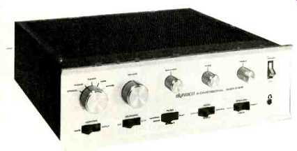
Dynaco products have long had the reputation of being well-designed, with top performance, a minimum of "frills," and a rather simple styling. The SCA-80Q is no exception and as it can be obtained as a kit, substantial savings can be made into the bargain! It is described as a "4-d amplifier" which means that it has a built-in speaker-matrixing circuit to feed difference information to two rear speakers. The method was described at some length in our July, 1970 issue [--Borbely's article in the May, 1972 issue, A Matrix Type Unit For … the arrangement of the connections.] and it is sufficient to say that out-of-phase information is recovered from the two channels and applied to the rear speakers. This information usually consists of hall reverberation or ambience and so this kind of simple matrixing can improve the realism of the reproduction-giving what Dynaco calls a four-dimensional effect. Not to be confused with the CBS SQ, EV or Sansui quadraphonic systems, but of course the 4-d does not need an additional amplifier. In any case, it is an optional facility and can be disregarded.
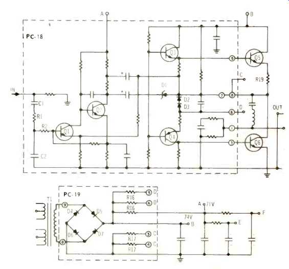
Fig. 1--Basic circuit of power amplifier stages.
Looking at the control panel, the selector switch is on the left, then the VOLUME, BALANCE and TONE controls, with the ON/OFF switch on the right. At the bottom are slide switches for TAPE MONITOR, LOUDNESS, FILTER, MODE, and SPEAKERS. Under the ON/OFF switch is a headphone socket-a must these days.
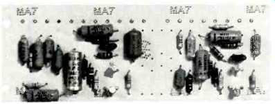
Fig. 2--Preamplifier board.
Circuit Descriptions
At first sight, the circuit arrangement looks very simple and straightforward, but there is an ingenious protection circuit which will be explained later. Two d.c.-coupled transistors are used in the preamplifier with phono input taken to the first one and equalizing applied by a feedback loop from the emitter of number one to the collector of number two in the usual manner. High level inputs-tape, tuner, and so on-are taken to the next stage via the volume and balance controls. This stage consists of another d.c.-coupled pair and the output is taken to a passive tone control network followed by the power amplifier. The basic circuit is shown in Fig. 1. Q1 and Q2 form a d.c.-coupled pair with a stabilizing feedback loop applied between the second emitter to the input base.
Q3 and Q4 ate a complementary pair driving the two output transistors. D1, D2, and D3 form part of the protection circuit and operate as follows: If the current in Q4 rises to equal that in R16 and R17, the diodes no longer conduct and the Zener D1 then conducts and effectively makes a short circuit between the input or Q3 and Q4 and the output from Q5 and Q6. Thus, excessive currents cannot be induced in the output and driver transistors. The protection circuit triggering point is determined by the reference voltage developed by the R16 and R17 bleed resistors. As I said before, an ingenious circuit which works, as I proved to my satisfaction. Power supply is taken from á conventional bridge rectifier and no-load voltage is about 74.
How It Went Together
Although the manual is not as detailed and elaborate as some others, those people with some technical knowledge will have no difficulty in following the instructions. All the boards with the exception of the power supply board are already assembled and so the biggest job is wiring and assembling the front panel controls and mounting the components. Total time I would estimate at 6 hours but it probably could be completed in less. Figure 2 shows a preamplifier and tone control board and Fig. 3 shows the driver stages.
The output transistors are mounted on heat sinks which also serve as holders for the driver board. (See Fig. 4). Incidentally, the boards are pre-tested, so there is little chance that the amplifier will fail to meet specifications.
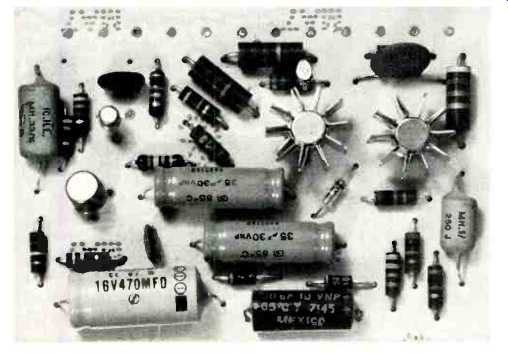
Fig. 3--Driver stages.
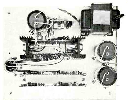
Fig. 4--View of partially completed unit.
Performance
Power output and distortion characteristics are shown in Fig. 5 and 6. It will be seen that the specifications are met with a comfortable margin. Power bandwidth came out at 10 Hz to just over 50 kHz as shown in Fig. 7. The loudness control gave a bass lift only as can be seen from Fig. 8. The tone control curves are shown in Fig. 9. Overall frequency response was excellent, being only 2 dB down at 10 Hz and 1.1 dB down at 100 kHz. This is reflected in the square wave performance as shown in the photos (Fig. 10). Sensitivity was 150 mV (for 56 W) for the high level inputs and 3.2 mV for phono inputs (there are two). Hum and noise was-82 dB for high level and-65 dB for phono. Separation came out at 55 dB at 1 kHz and 48 dB at 10 kHz. I have left the filters until last because the arrangement is a little unusual. The switch is a three-position rocker and the three choices are FLAT, RUMBLE, and NARROW BAND (See Fig. 11). Thus the low frequencies can be cut independently but if a top cut is required then the low frequencies are reduced also. Under some conditions this will undoubtedly give a tonal balance, but there are many occasions when a high frequency roll-off is required to remove distortion or that "chromium-plating" without affecting the bass response.
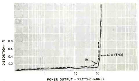
Fig. 5--Power output and THD and IM distortion. Taken with 4 ohm load, both channels
driven simultaneously.
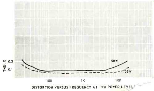
Fig. 6--Distortion versus freq.
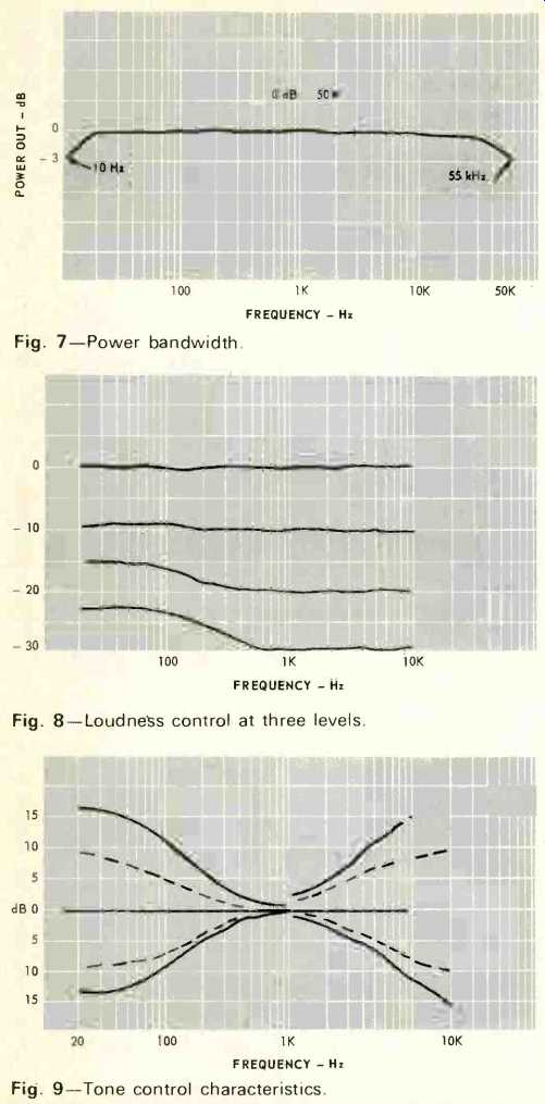
Fig. 7--Power bandwidth.
Fig. 8--Loudness control at three levels.
Fig. 9--Tone control characteristics.
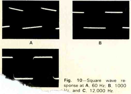
Fig. 10--Square wave response at A, 60 Hz; B, 1000 hz, and C, 12,000 Hz.
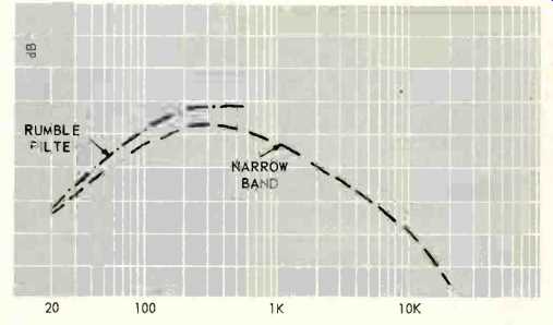
Fig. 11--Filter characteristics.
Listening Tests
In operation, the SCA-80Q performed as well as the measurements indicated, transient response was good and the reproduction was clean with no sign of edginess due to crossover distortion. On an A-B comparison with a most respected tube amplifier (circa 1965), there was no question of the Dyna's superiority. Not only was the bass response tighter but the high frequencies were crisper and more natural sounding. The 4-d speaker positions were tired with mixed results. Some records sounded at least as good as with a SQ decoder--particularly those made by the MS microphone placement--but others did not. Volume level of the rear speakers is 6 dB lower than the front--which is fine for most material---or listening positions for that matter. As I said previously, this kind of simple matrix will not give the sound location of the more elaborate decoders used with encoded discs but it is surprising what a difference those two extra speakers can make. The sound has a more exciting, spacious quality and in many instances switching off the rear speakers will make the reproduction flat and un-natural. Incidentally, the speaker switch has a spring-return null position which enables the four speakers to be balanced accurately--Dyna thinks of everything! The only real criticism I have concerns that filter switch but of course it can be modified quite easily by anyone who feels strongly enough about it.
-T.A.
(adapted from Audio magazine, July 1972)
Also see:
Dynaco SCA-80 Stereo Integrated Amplifier (Aug. 1970)
Dynaco Stereo 80 Basic Stereo Amplifier Kit (Feb. 1970)
Dynaco Stereo 400 Power Amplifier (Equip. Profile, May 1975)
Dynaco PAT-5 Preamplifier (Equip. Profile, Feb. 1976)
Dynaco AF-6 AM/FM Tuner (Equip. Profile, Sept. 1974)
Dynaco A-25XL Loudspeaker (Nov. 1976)
Dynaco Stereo 70 Series II Tube Amp (Nov. 1992)
= = = =