MANUFACTURER'S SPECIFICATIONS:
FM Section
IHF Sensitivity: 1.8 µV.
S/N Ratio: 70 dB.
Selectivity: 75 dB.
Capture Ratio: 1.2 dB.
Harmonic Distortion: Mono, 0.3%; Stereo, 0.4%.
Stereo FM Separation: 1kHz, 40 dB.
AM Section
Sensitivity: 100 µV/meter (internal antenna).
Selectivity: 32 dB.
Harmonic Distortion: 50%
Modulation, 1.5%.
Amplifier Section
Power Output: 70 watts continuous per channel, 8 ohms, 20 Hz to 20 kHz with no more than 0.3 total harmonic distortion.
THD at Rated Output: 0.3%.
IM Distortion: 0.3%.
Frequency Response: 8 Hz to 40 kHz ± 1 dB.
General Specifications
Dimensions: 18 in. W. x 5 3/4 in. H. x 15 in. D.
Weight: 40 lbs.
Power Consumption: 450 watts maximum (100, 117, 220, or 240 V, 50/60 Hz).
Price: $499.95.
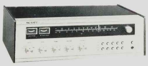
This somewhat abbreviated list of specifications above is no indication of abbreviated performance capability for this top-of-the-line receiver from H.H. Scott, Inc. As many Audio readers are aware, Scott is one of the oldest and most venerated names in high fidelity. Several years ago, when other U.S.-based companies sought to fight rising costs by producing their products abroad, Scott insisted on maintaining a total "made in the U.S.A." stance and found itself unable to compete in the high fidelity marketplace. Since then, the balance has shifted somewhat, and, buoyed by outside financing, the company is very much alive and back in business at its plant in New England. Initial output consisted of many models which were carried over from earlier designs, but the Model R77S represents Scott's first totally redesigned receiver under its new management and engineering team. The new approach seems to be to give the consumer lots of good performance on the inside without cluttering the front panel with superfluous controls and switches (and, apparently, without cluttering the spec sheets with too many technical terms and specifications). The result is one of the neatest and cleanest looking front panels we have seen in some time. Silver in color, it has five machined, rotary, control knobs at the lower left which handle Input source, Bass, Treble, Balance and Volume adjustments. Both tone controls and the balance control have easy-to-feel detent positions at their mid-rotation points (for flat response and equal gain to both channels). At the lower right of the panel is a push-button Power on/off switch and a stereo phones jack. Immediately to the left are two neat rows of five pushbuttons each. The lower row is devoted entirely to speaker selection and, since it is possible to connect three sets of speakers, offers selection of individual sets plus a pair of buttons for 1 & 2 or 1 & 3. There is no provision for operating all three pairs of speakers simultaneously since this could present dangerously low output impedance to the amplifier section.
The blacked-out tuning area lights up in soft green when power is applied, disclosing a long AM and FM dial scale, an illuminated dial pointer (red), and illuminated signal strength and tuning meters. Program source selection is also indicated by means of lit-up words below the dial scale. A rotary tuning knob, equal in size to the other control knobs, is located at the extreme right of the dial area. Flywheel action is moderately effective.
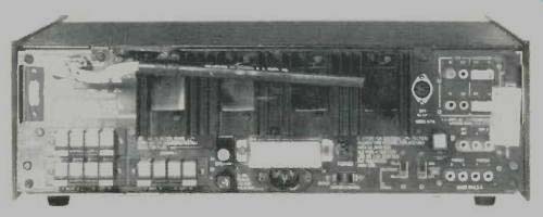
Fig. 1--Rear view of receiver.
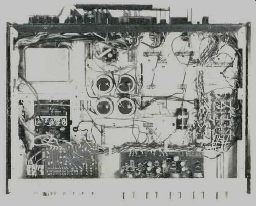
Fig. 2--Internal view of the receiver.
The rear panel, pictured in Fig. 1, shows the three sets of speaker terminals, which are the spring-loaded, push-to insert-cable type, as is the chassis ground terminal.
Screw terminals are provided for 300-ohm FM and external AM antenna connection while a coaxial connector is supplied for 75-ohm FM antenna installation. There are individual speaker line fuses as well as a power line fuse, a switched a.c. receptacle, twin pairs of phono inputs (one pair of which is equipped with a slide switch for varying input sensitivity from 3 mV to 6 mV), Tape In and Out jacks (for the tape monitor facility), extra tape input jacks, and a detector output jack for use with future 4-channel FM adaptors. A pair of jumpers interconnect sets of Accessory jacks. These really constitute a second Tape Monitor circuit interruption point, rather than the more familiar preamp-amp separation facility. There is a slide switch for changing FM de-emphasis from 75 microseconds to 50 microseconds (used in Europe). Scott could have easily (and may yet) provided a 25 microsecond position for Dolby FM instead, since there is no reason for the 50 microsecond position in the U.S. A DIN connector can be used instead of the Tape In and Out jacks if your tape deck is so equipped. Pivotable AM ferrite antenna and power line cord are unpluggable for packing and shipment.
Circuit Description
An internal view of the receiver is shown in Fig. 3, and a complete block diagram of the unit is in Fig. 3. The silver-plated FM front-end features a MOS-FET used for r.f. amplification. The i.f. section includes a pair of 6-pole lumped filters and two high-gain integrated circuits. Limiting is provided by the second i.f. amplifier and the ratio detector. AGC is provided from the i.f. strip in a d.c. feedback loop to the FET r.f. amplifier on the front-end. All multiplex decoding functions are performed by an IC chip which uses a phase lock loop (there are no coils to adjust) and contains the equivalent of 58 transistors and four diodes. The AM tuner section uses an FET r.f. amplifier and mixer and an IC circuit for the i.f. section. AM detection is by a voltage doubler circuit.
Negative feedback is used both for RIAA equalization in the preamplifier and for FM de-emphasis as noted previously. The power amplifiers have differential input with full complementary power-output configuration for direct coupling to the speakers. A dual voltage feedback regulator circuit powers all circuitry except the power amplifiers.
In addition to the speaker fuses, the receiver has a fast acting electronic protection circuit which protects output devices even in the event of a short-circuit across the speaker terminals.
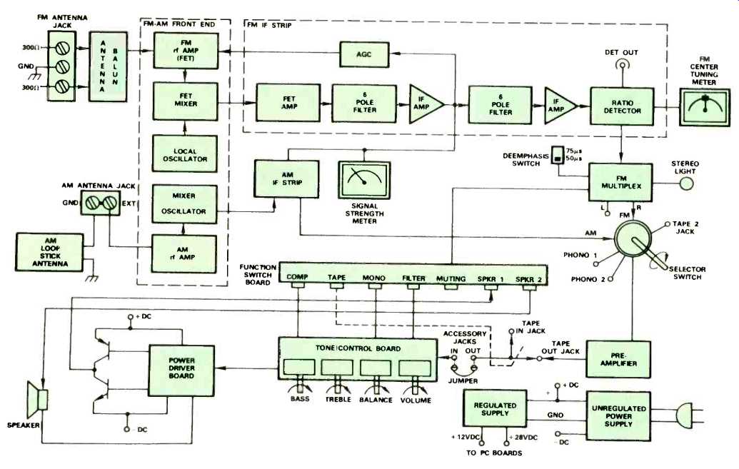
Fig. 3--Block diagram of Scott R77S receiver.
FM Measurements
In reading the instruction manual supplied with the receiver, we noted that some of the specifications listed are at variance with those supplied in the published advertising brochure. For example, the booklet claims 1.9 µV IHF FM sensitivity (which is exactly what we measured) whereas the brochure claims 1.8 µV. Fig. 4 is a plot of signal-to-noise (quieting) and distortion characteristics in mono and stereo for a 1 kHz audio signal. 50 dB quieting in mono was obtained for a signal strength of just under 5µV, while ultimate 5/N measured 71 dB, a bit better than claimed. Maximum S/N in stereo measured 64 dB. THD for strong signals was 0.26% in mono, 0.45% in stereo. Selectivity was considerably better than claimed, measuring 87 dB, while Capture Ratio measured 1.4 dB. Image Rejection and Spurious Response Rejection (not supplied in the specs) were 58 dB and 90 dB respectively.
As shown in Fig. 5, stereo FM separation reached a maximum of 40 dB at mid frequencies, tapering off to 32 dB at 50 Hz and just under 30 dB at 10 kHz. THD was well under 0.5% for all audio frequencies in mono and below 1.0% for all significant audio frequencies in the stereo mode.
Amplifier Measurements
Both the specification sheet and the instruction manual of the R77S were printed prior to the effective date for the new FTC power rule and in addition, the brochure lists rated THD and IM for the power amplifier section at 0.3% while the owner's manual lists 0.5% In order to have a point of reference, our measurements were based on 0.3%. As shown in Fig. 6, the amplifier delivered 75 watts per channel at mid frequencies for 0.3% THD. At all power levels below this point, THD was well under 0.1% and IM distortion was below 0.05%, a figure we would normally expect to find in separate amplifiers of highest quality, rather than in all-in one receivers. Based upon the 0.3% THD rating, the receiver falls short of maintaining full power output capability (70 watts per channel) down to 20 Hz, as can be seen in the graph of Fig. 7. Under those conditions, the power band (as the FTC calls it) extends from 33 Hz to above 20 kHz. If the 0.5% THD rating is to govern, power band (full power at rated distortion) would be stated as extending down to 25 Hz or so. At half power output (35 watts per channel), THD remains consistently well under 0.1% for all audio frequencies.
Phono input sensitivity was measured at 2.8 mV and 7.5 mV, depending upon the setting of the sensitivity switch on the rear panel. Phono input overload was 45 mV for the high sensitivity position and 140 mV for the lower sensitivity setting. Tone control range, as well as loudness compensation and high-cut filter characteristics are plotted in Fig. 8. The filter and loudness circuits are activated by two of the upper row of five buttons on the front panel, other buttons in that cluster taking care of such functions as Tape Monitor, FM Muting and Mono/Stereo switching. The loudness circuit adds boost at both low and high frequencies with major compensation occurring at the low end. Curve shown is for a setting of-30 dB with respect to maximum volume control position. The high frequency cut-off filter has a turnover frequency of about 4 kHz, making it more effective in reducing scratch and hiss than might be with the treble control.
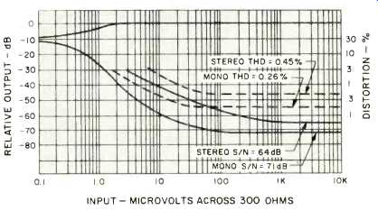
Fig. 4--FM quieting and distortion characteristics.
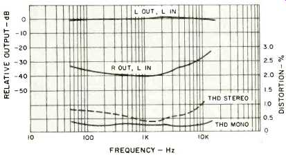
Fig. 5--FM distortion and separation vs. frequency.
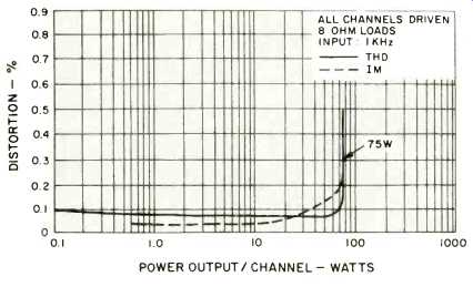
Fig. 6--Harmonic and intermodulation distortion of amplifier.
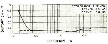
Fig. 7--Amplifier distortion vs. frequency.
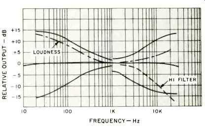
Fig. 8--Tone control range, filter and loudness compensation.
Damping factor was measured at 35, referred to an 8-ohm load. The high level inputs ("Tape 2") have an input sensitivity of 410 millivolts. Hum and noise in the high sensitivity phono position measured 65 dB, while in the low sensitivity setting, a reading of 75 dB was observed for residual hum and noise. All of these readings are excellent, since no weighting curve was applied and all readings were referred to full power output. Hum level in Tape 2 (which is really an AUX position) was 81 dB referred to full output, while with volume control set to its minimum position, residual hum and noise measured 85 dB below full output.
Listening and Use Tests
Scott has chosen just the right threshold points for stereo switching and interstation muting. With a stereo switching threshold set at 7µV, stations received in stereo during our listening tests were sufficiently free of noise (even the weaker ones) to justify that switching level. While station counting has become meaningless in our area (we encounter virtually no interstation regions on the dial, with the exception of a couple of MHz at the low end of the band, where educational FM comes and goes), we can say that reception was clean and low in distortion, and tuning was precise and not nearly as critical as on some competitive units we have measured. Center-of-channel indication on the meter corresponded exactly with minimum distortion points and dial calibration was just about perfect. Interstation muting is set at about 7 microvolts, so that when this feature is used, one is assured that any stations which overcome the threshold are received with well over 50 dB of quieting. FM DX-ers have the option of defeating the mute circuit, but we found this unnecessary and were able to pick up normally weak signals with ease and without having to listen to interstation noise for that privilege.
The Scott R775 is definitely in the "high" power class, and so we used it to drive low efficiency book-shelf speakers in our listening tests. We were able to achieve more than adequate listening levels in a large listening room, and there was no audible evidence of amplifier clipping or distortion, even when records with wide dynamic levels were played.
The receiver is simple to operate and we urge prospective users not to be deterred by the seeming lack of complexity on the front panel. (Some hi-fi buffs still judge a product by the number of gadgets, switches, knobs and levers on the front panel.) Despite its "simple" outward look, the R775 is a sophisticated, up-to-date stereo receiver that ranks with the best of them. It is conservatively designed, meets most all of its specifications, and does very well in those secondary aspects which the company chose not to specify, too. In terms of its price/performance ratio, this Scott receiver is well worth its price.
-Leonard Feldman
(Adaped from Audio magazine, May 1975)
Also see:
Scott (H. H. Scott) Model 477 AM/FM Stereo Receiver (Equip. Profile, Oct. 1972)
Scott Model R-376 AM/FM Stereo Receiver (Equip. Profile, June 1977)
Scott Slimcom 650SL (One-Brand Systems, Jan. 1983)
= = = =