MANUFACTURER'S SPECIFICATIONS
FM Tuner Section: IHF Sensitivity: 1.9 µV. S/N Ratio: 70 dB. THD (Mono): 0.5%. Capture Ratio: 2.5 dB. Selectivity: 40 dB. AM Suppression: 55 dB. 38 kHz Suppression: 95 dB. Spurious Response Rejection: 80 dB. Stereo FM Separation: 35 dB.
AM TUNER SECTION: IHF Sensitivity: 100 µV/Meter. Selectivity: 32 dB. THD (@60% Modulation): 2.0%. S/N: 40 dB. V.F. Rejection: 30 dB. Image Rejection: 48 dB.
AMPLIFIER SECTION: Power Output: 70 watts continuous, 8 ohm loads/channel, both channels driven; 100 watts continuous/channel, 4 ohm loads. THD at Rated Output: 0.5%. Power Bandwidth: 15 Hz to 40 kHz. Damping Factor: 30. Input Sensitivity: Phono, 8 mV/4 mV; Mic, 5.5 mV; High Level; 550 mV. Hum and Noise: High Level Inputs,-75 dB; Low Level Inputs,-65 dB.
General Dimensions: 17 1/2 in. W. x 6 in. H. x 15 1/2 in. D.
Shipping Weight: 30 lbs.
Power Consumption (at 117 V A.C.): 500 watts max.
Suggested Retail Price: $419.90.
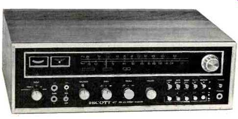
H. H. Scott's rugged high power Model 477 stereo receiver is a good example of how solid-state technology has made possible powerful receivers no larger or heavier than units offering half as much power just a few years ago. The front panel of the receiver, shown above, differs in styling from earlier Scott designs in that it is primarily matte black in color, highlighted by a heavy anodized aluminum edge frame and dial frame. Metal knobs and push buttons of matching color result in a clean uncluttered look, despite the abundance of controls. Along the lower half of the panel are rotary knobs for selection of INPUT, and for BALANCE, VOLUME, BASS and TREBLE levels. The tone control knobs are of the dual concentric type (with clutch action for simultaneous rotation), affording individual channel adjustment of bass and treble. At the right end of the panel are two banks of push buttons. The upper five buttons are of the push-push type and activate the LOUDNESS,TAPE MONITOR, MONO/STEREO MODE, HIGH FREQUENCY FILTER and FM MUTING circuits. The lower five buttons are of the interlocking type (pushing one button releases any other previously depressed button) and control choice of speaker pairs. Up to three pairs of stereo speaker systems can be connected to the 477, but only two pairs are selectable at any given time. Buttons are marked 1, 2, 3, 1&2 and 1&3. A separate push-push POWER on-off button is located at the extreme right end of the panel, above the usual stereo headphone jack. Near the selector switch are TAPE IN and OUT jacks wired in parallel with those to be found on the rear panel and a pair of microphone input jacks which utilize the phono-preamp circuitry for low-level preamplification.
With power applied to the unit, the blacked out upper portion of the panel becomes illuminated to disclose well calibrated FM and AM dial scales, a signal strength meter as well as a center-of-channel tuning meter. Function indicator lights below the dial scale indicate selected program source and there is a stereo indicator light as well. A large tuning knob, coupled to an effective flywheel, completes the front panel layout.
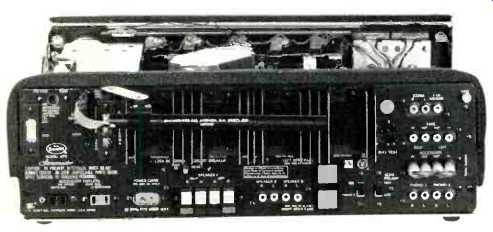
Fig. 1--Rear panel of the Scott 477
The rear panel (shown in Fig. 1) is a good deal "busier" looking than the front panel. At the left end are antenna terminal strips for external AM or 300 ohm FM antenna transmission lines. There is also an antenna jack for connection of 75 ohm antenna plugs usually used with coaxial types of transmission lines and a slide switch for selecting the correct antenna impedance. A pair of a.c. convenience receptacles (one switched, the other unswitched) are located below the antenna strips. The main speaker terminals accept the stripped end of your speaker cable by simply pressing on a spring-action button which discloses a small hole into which the bare wire ends can be pushed. Releasing the button clamps the wire in place. Connection of the second and third sets of speakers is made by means of phono-tip plugs. A circuit breaker reset button eliminates the need for a line fuse, but two speaker fuses are supplied in just about the cleverest fuse holder we have run across. Pressing the lower portion of the square fuseholder cap releases the fuse-no unscrewing required. A pair of slide switches select phono or microphone inputs and equalization as well as phono input sensitivity. There are the usual jacks for TAPE IN and OUT, extra high level inputs, PHONO 1 and 2 and a FOUR CHANNEL DECODER jack intended for some future demodulator-decoder which may be required when and if the FCC approves some form of discrete four-channel FM broadcasting. A pair of short jumper cables interconnect IN and OUT jacks labeled ACCESSORY. With the jumpers removed, these would be the points at which you could connect such extras as a matrix four-channel decoder or any of the other "accessory" products which require another "circuit interrupt" point. A four terminal test jack for easy access to bias voltage and a grounding terminal complete the rear panel layout.
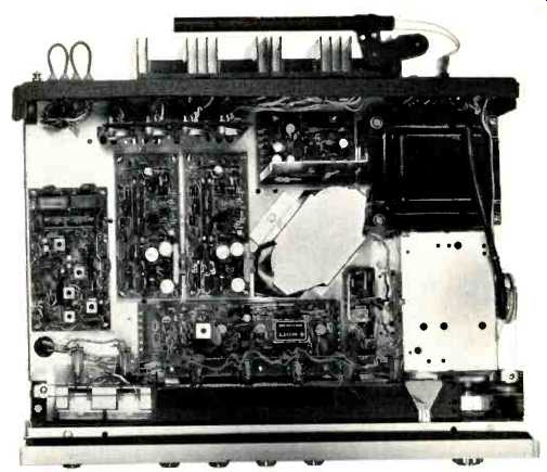
Fig. 2--Interior of the Scott 477. Note the modular PC board approach to
design.
Circuitry
H. H. Scott was among the first companies to pioneer the modularized approach in component high fidelity manufacture and in the Model 477 they have refined this approach even further. We counted no less than 12 individual board modules, not including the input antenna balun. Many of these modules can be seen in the top view of the inside of the 477 chassis shown in Fig. 2. This approach, besides reducing the amount of point to point wiring and soldering, enables Scott to offer rapid servicing, if required. If you ever have to send a Scott unit such as this to the factory or an authorized service station for repairs, instead of "trouble shooting" the defective module, it is replaced by an identical module for a flat fee of $10.00, speeding the return of your unit. Solderless "tension wrap" connections are used wherever possible, eliminating a good deal of hand soldering and attendant "cold solder joint" possibilities.
The front-end of the 477 employs an FET r.f. amplifier for FM and another FET as an r.f. AM amplifier. Mixer and oscillator stages are bi-polar NPN devices for the FM section. Three high-gain IC's are used in the FM i.f. section along with a six-pole interstage filter which does away with all i.f. alignment except touch-up of the ratio detector transformer. The AM i.f. section consists of an input FET, followed by a high-gain IC stage and a dual-diode detector.
The multiplex module of the 477 utilizes nine bipolar transistors and an FET in one of the most sophisticated stereo decoder circuits we have examined. It takes into account background noise and signal strength before automatically switching from mono to stereo reception when a stereo broadcast is tuned in. A bridge demodulator circuit plus 38 kHz notch filters at the left and right outputs account for the excellent 38 kHz rejection figures cited in the manufacturer's specifications (and easily met in practice). A single 17-pin dual inline IC is the main component of the stereo preamplifier section of the receiver, with equalization components mounted external to the IC on a small p.c. board located close to the low level input jacks. Tone control circuits are of the feedback (Baxandall) type and utilize an FET for each channel. Further voltage amplification, driver circuits and electronic protection for drivers and output stages are incorporated in two six-transistor modules (one for each channel). The input stage of each of these modules takes the form of a differential amplifier, with its inherent stabilizing characteristics (both thermal and signal-level). Complementary-symmetry output stages are operated from positive and negative 44 volt supplies which permit direct coupling to the loudspeakers at zero d.c. potential. All lower voltage supplies are electronically regulated by another pair of module boards.
Electrical Measurements
While IHF FM sensitivity was 2.5 µV, only 5 microvolts of signal input was enough to provide 54 dB of quieting-an excellent figure. Ultimate quieting was a remarkable 75 dB, and mono harmonic distortion measured a low, low 0.12% at 100% modulation (this compared to 0.5% claimed). These important characteristics are plotted in Fig. 3. Here, then, is a receiver whose FM distortion characteristic is as good as its amplifier THD characteristic-quite a rarity. THD in FM at other frequencies (not plotted) was measured and found to remain below 0.3% over the useful audio spectrum.
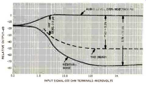
Fig. 3--Mono FM characteristics.
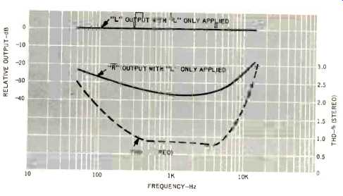
Fig. 4--Stereo FM separation and THD versus frequency.
Stereo separation, shown in Fig. 4, exceeded published specs by a couple of dB at mid-band frequencies, decreasing to about 25 dB at 50 Hz and 10 kHz. As you can see in Fig. 4, something new has been added to our reports. As we promised, we have begun to measure THD at various frequencies in stereo, and a word about these measurements is in order.
It is a fact of "stereo multiplex life" that when trying to recover high audio-frequency stereo information, beat frequencies occur at audio frequencies above about 6 or 7 kHz.
For example, a 10 kHz signal may beat with the ever-present 19 kHz sub-carrier frequency to produce an unwanted tone of 11 kHz. While this tone is not, strictly speaking, "harmonic" distortion, it will nevertheless be measured on a conventional harmonic distortion analyzer. The instantaneous presence of such "beats" when listening to music is far less objectionable than the "percentages" would seem to indicate, since they are "random" and rather momentary. Nonetheless, some receivers exhibit this undesirable characteristic more than others, and we shall be reporting on it in future reports for comparative purposes. Since this is the first such presentation, and since any figure of 3% THD might frighten the reader (that figure is observed at 15 kHz in Fig. 4), we must advise readers that we have measured percentages as high as 10 and 15 percent at 15 kHz on competitive equipment! Evidently, this is a much overlooked area in design and achieving a figure which never exceeds 3% at any useful frequency is a compliment to Scott engineering, rather than the other way round. Note, too, that throughout most of the very important mid-band region, stereo THD is well under 1%.
Continuous power output with 8 ohm loads turned out to be 72.6 watts per channel at mid-frequencies, a bit better than claimed, while IM distortion, for which no manufacturer's spec is provided, measured 0.5% at exactly 70 watts output per channel. (In all cases, both channels were driven.)
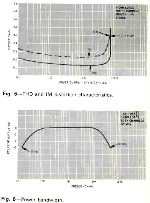
Fig. 5--THD and IM distortion characteristics.

Fig. 6--Power bandwidth.
These characteristics are plotted in Fig. 5. Power bandwidth of the 477 extends from 15 Hz to 42 kHz, as shown in Fig. 6. Figure 7 is a plot of harmonic distortion versus frequency for power/channel levels of 50 watts and 1 watt and at no frequency or power level between the two extremes did THD exceed rated 0.5%.
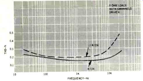
Fig. 7--Frequency versus THD at 1 watt and 50 watts per channel.
Tone control, loudness compensation, and high frequency filter characteristics are plotted in Fig. 8 and are conventional but satisfactory. The filter switch, in addition to providing a six dB roll-off characteristic, also "cross-feeds" stereo information between channels, reducing stereo separation somewhat but greatly cancelling stereo FM noise which appears under weak signal conditions.
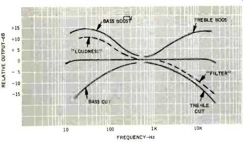
Fig. 8--Tone control, loudness, and high filter characteristics.
Listening Tests
Musical reproduction in our test set-up using the Scott 477 was flawless. We did, however, find that it was easier to get the volume level up to where we like it in the FM mode than it was when listening to recordings, where we were pretty close to the top of the volume control. We attribute this to the somewhat low gain of the phono inputs (4.0 mV and 8.0 mV). Some 2 to 2.5 mV for the high gain inputs is more typical of receivers these days, since a great many cartridges put out that order of voltage and since so many people use low-efficiency speakers. We did "make it" with our set-up (which includes both a nominally 2 mV rated cartridge and about as low-efficiency speakers as you can buy), but with not too much to spare on the volume control.
The superiority of the FM circuitry was quite apparent. We logged 44 stations with the muting circuit activated and some 47 with the muting defeated. Interestingly, however, the three new stations received when we defeated the mute circuit were quite listenable. Considering the fact that they must have been coming in at signal strengths below 6 microvolts (the threshold point of the mute circuit on the unit we tested), one can begin to see how important that early, steep quieting characteristic really is. A word of caution about the tuning characteristic of this unit: If you detune a stereo station significantly, the automatic stereo switching circuit flips back to mono. This may actually be a blessing in disguise, for, with that degree of mis-tuning, the stereo separation would be off anyway and distortion would probably be higher than you'd like to hear. In any event, we found that the center-of-channel meter coincided exactly with the maximum signal strength indication on the companion meter, so this should provide no problems to the user.
We ran the 477 for several hours per day for more than two weeks at high power levels (both on the test bench and under musical reproducing conditions) and found that heat is no particular problem for this hefty receiver.
In summary, if you feel you need 70 watts per channel capability in a receiver and have just around $400.00 to spend, this product of the many years of Scott experience and engineering skill should not be overlooked. Always noted for their expertise in r.f. and FM design, they have now produced a first-class high-power solid-state amplifier in a price category that speaks well for American-made products. More power to the good people in Maynard, Massachusetts!
-Leonard Feldman
(Adaped from Audio magazine, Oct. 1972)
Also see:
Scott R77S AM/FM Stereo Receiver (Equip. Profile, May 1975)
Scott Model R-376 AM/FM Stereo Receiver (Equip. Profile, June 1977)
Realistic (Radio Shack) Model STA-225 AM/FM Stereo Receiver (Dec. 1975)
= = = =