Akai Model AA-1050 AM/FM Stereo Receiver
MANUFACTURER'S SPECIFICATIONS
FM Tuner Section
IHF Sensitivity: 1.8µV. S/N Ratio: Better than 75 dB, mono. Selectivity: Better than 100 dB. Capture Ratio: 1.0 dB. THD: Mono, less than 0.15%; stereo, less than 0.3°%o. Image Rejection: 95 dB. I.F. Rejection: 100 dB. Spurious Rejection: 90 dB. Stereo Separation: 1 kHz, better than 40 dB. Muting Threshold: Variable, from 3µV to 300 µV. AM Tuner Section
IHF Sensitivity: 180 µV/M (internal antenna); 8µV (external antenna). Selectivity: 30 dB. Image Rejection: 55 dB. I.F. Rejection: 45 dB. S/N Ratio: Better than 50 dB. THD: Less than
0.6V0. Amplifier/Preamplifier Section Power Output: 50 watts per channel min. rms, at 8 ohms, from 20 Hz to 20 kHz. Rated THD: 0.15'ío. S/N Ratio, IHF: Phono, 80 dB; AUX, 90 dB. Input Sensitivity: Phono 1 & 2, 3
mV; AUX, Tape, 150 mV. Phono Equalization: RIAA ±1.0 dB. Tone Control Range: Bass, ±10 dB at 100 Hz; treble, 1-10 dB at 10 kHz. Filters: High cut,-10 dB at 10 kHz; low cut,-8 dB at 50 Hz.
General Specifications
Dimensions: 18.9 in. W x 6.1.in. H x 15.4 in. D. Weight: 28.6 lbs. Suggested Retail Price: $450.00.
Akai Electric Company, Ltd. of Japan, whose products are sold by Akai America Ltd. in the U.S., is perhaps best known in this country for its fine line of stereo tape decks, both open reel and cassette. The fact is that the company also produces an extensive line of purely electronic products, including both stereophonic and quadraphonic receivers. Interestingly, at a recent industry trade show, Akai was one of the few companies (if not the only one) to introduce two new four-channel receivers at a time when other companies were backing away from this format.
The Model AA-1050, tested for this report, is the company's top stereo receiver. Its styling follows the new format adopted by so many better known brands, in that the old, traditional blackout dial treatment has been replaced by a bright gold dial area, of narrow but extra long dimensions, which blends nicely with a brushed aluminum front panel. Numerals, screened in a contrasting dark color, are highly visible even when the unit is not powered and the only other items within the dial area are the familiar stereo indicator light and an AFC light just below it. FM calibration is linear, with markings evenly spaced at every half of a Megahertz. A good sized tuning knob, coupled to an effective flywheel is located to the right of the dial area. Separate cutouts in the panel below the left section of the dial disclose signal strength and center-of-channel tuning meters which are also well illuminated when power is applied. Adjacent to the meters are the low and high cut filter pushbuttons and an audio muting button which reduces overall listening level by a fixed 20 dB when depressed. Next come four tiny indicator lights which denote program source selected, the FM muting switch and an associated small rotary control which varies muting threshold. Along the lower edge of the panel are a Power on/off switch, headphone jack, speaker selector switch (with every possible combination of two out of three or one out of three pairs of speakers which may be connected to the receiver, plus an "off" position for headphone-only listening), Bass, Treble, Balance and Volume rotary controls, a Loudness switch, Mono/Stereo Mode switch, a Tape Monitor switch (with positions for dubbing as well as monitoring of either of two tape decks which may be connected to the unit) and a program selector switch. The selector switch includes positions for mono as well as automatic FM listening, and in the latter position the stereo multiplex circuits automatically are switched in which a stereo FM transmission is received.
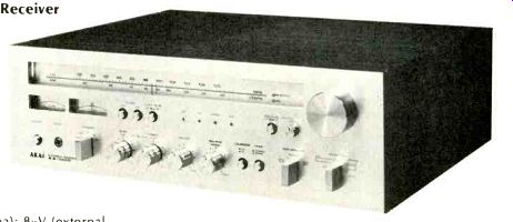
The rear panel of the Model AA-1050, pictured in Fig. 1, has separate terminals for 300-ohm FM and external AM antennas, as well as a coaxial connector and clamp for 75-ohm transmission lines. Dual phono input pairs, AUX inputs, and the two sets of Tape out and in jacks are neatly clustered together below the pivotable AM ferrite bar antenna, while the three sets of speaker connection terminals (of the spring-loaded type which require insertion of the stripped wire ends of speaker cables) are located at the opposite end of the rear panel, each set color coded for proper phasing of speaker wires. One switched and two unswitched a.c. convenience outlets are also located on the rear panel for connection of other components. A DIN multiple-pin connector parallels the Tape-1 input/output jacks for those tape decks that are equipped with that type of plug.
Akai does not supply a schematic diagram with the Model AA-1050, so it was not possible for us to study the circuitry in detail. We did, however, remove the vinyl-clad wood cabinet supplied with the unit and examined internal construction and layout (see Fig. 2). A separate, sealed front-end, employing a four-section FM tuning capacitor and a three gang AM tuning capacitor, is used, and it is mounted directly above the tuner board, well towards the rear of the chassis and close to the antenna input terminals. Both the tape and selector switches are coupled via long shafts from their desirable rear-of-chassis locations to eliminate needlessly long shielded wire harnesses. Power supply parts, including a good-sized power transformer, are centrally located and well ventilated, as are the power amplifier p.c. module and vertically mounted output transistors and heat sink assembly at the opposite end of the chassis from the tuner board. Smaller, secondary p.c. modules up front take care of low-level tone control and voltage amplification circuits, and there is a minimum of inter-module wiring, all neatly dressed and properly tied down to prevent variations in performance from unit to unit. Rather surprisingly, the heat sink assembly is not black colored (as are so many others, for better heat transference), but this does not seem to bother the receiver thermally, as evidenced by our later heat run and power output tests. A protective metal screen covers the power output area, providing additional heat conduction and preventing the possibility of minor electrical shock in the event that inquisitive enthusiasts insist upon removing the main wood cover, as we did.
FM Performance Measurements
It is always a pleasure to come across an FM tuner or the FM tuner section of a receiver that meets its usable sensitivity spec. As readers of our previous test reports know, this spec is not all that significant, but so many manufacturers publish one number and are content to "pass" production sets which fall somewhat short of meeting that number. In the case of our sample, IHF usable sensitivity measured exactly 1.8 µV (10.5 dBf) as claimed. More importantly, 50 dB of quieting in mono was reached with a quite low signal input of only 2.5 µV (13.35 dBf) in mono. Usable stereo sensitivity was 3.2 µV (15.5 dBf) and switching to stereo occurs at a very low 2.0 µV (11.4 dBf) with 32 µV of signal (35.5 dBf) required for 50 dB of quieting in the stereo mode. Signal-to+noise ratio in mono reached 73 dB for strong (65 dBf) signals and 67 dB in stereo. Only the distortion figures were at all disappointing for, even though 0.41% (mono) and 0.25% (stereo) are acceptably low numbers, both are short of the figures claimed by Akai (0.15% in mono, 0.3% in stereo). We suspect that the set was slightly out of alignment (particularly the FM detector section) since the center-of-channel meter needle always ended up slightly off-center when minimum distortion was achieved. That's okay for lab tests, but a consumer guided by the meter would not normally tune for lowest distortion because of this slight misalignment. We also noted that distortion in stereo was lower than in mono, a situation which usually connotes the addition of two larger values of distortion which tend to partially cancel each other. The built-in AFC circuitry of the Akai AA-1050 is such that it operates when tuning is close to optimum (at which time the "AFC" light on the front panel lights up), but we found that with the AFC light on, it is possible to detune the set sufficiently to cause significant increases in THD readings.
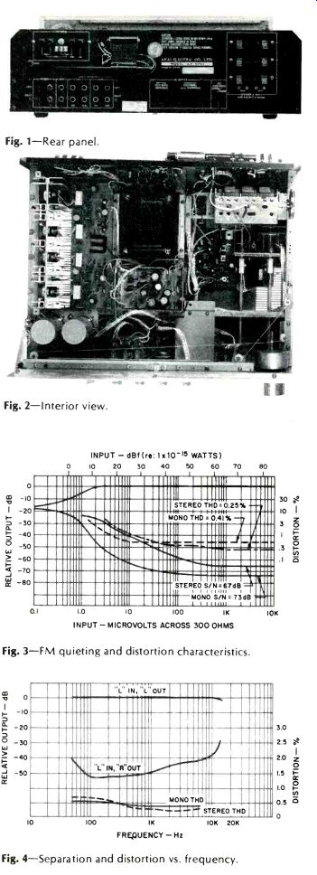
Fig. 1-Rear panel.
Fig. 2-Interior view.
Fig. 3-FM quieting and distortion characteristics.
Fig. 4-Separation and distortion vs. frequency.
Results of our quieting and distortion measurements versus signal input are plotted in Fig. 3, while distortion versus audio frequency and stereo separation for the FM section are shown in the graph of Fig. 4. While THD in mono and stereo were a bit on the high side, they did remain fairly constant at all tested frequencies up to 6 kHz, indicating a lack of "beats" in the stereo mode at higher audio frequencies. Separation was outstanding, reading nearly 50 dB at 1 kHz and an unusually high 40 dB from 50 Hz to nearly 10,000 Hz. Other specifications measured include a capture ratio reading of 1.2 dB, alternate channel selectivity of 88 dB, image and i.f. rejections of just over 95 dB and spurious response rejection of 90 dB, exactly as claimed.
All in all, a very fine set of measurements for an FM tuner section in a receiver in this price category.
Amplifier Section Measurements Although Akai's basic published statement of power output is quoted correctly, they also publish a "power bandwidth" which is listed as extending from 7 to 70,000 Hz. This, of course, is the "Old" IHF power bandwidth statement which is superseded by the FTC's definition of that term. In the FTC's version, power bandwidth means the extreme frequencies at which full power can be delivered at rated distortion (in this case, 20 Hz to 20 kHz, as stated in the basic power disclosure), whereas the older definition meant the frequencies at which half-rated power can be delivered.
Be all that as it may, the Akai AA-1050 did deliver its full rated 50 watts down to 20 Hz and all the way up to 33 kHz, with both channels driving 8-ohm loads, at the listed 0.15% total harmonic distortion. At mid-frequencies, power output increased to 58.8 watts per channel for around 0.3% THD, the point at which clipping was observed. The harmonic content at the clipping point is displayed on our spectrum analyzer 'scope face reproduced in Fig. 5 and is seen to include primarily third-harmonic content, with lesser contributions of higher order harmonics down some 75 dB below the fundamental signal (equivalent to about 0.018% each). IM distortion (which reached 0.28% at 50 watts output) and THD are plotted against power output in Fig. 6. THD versus frequency is shown in Fig. 7 and remains virtually constant over the entire audio range from 20 Hz to 20 kHz.
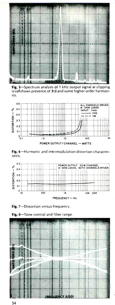
Fig. 5-Spectrum analysis of 1 kHz output signal at clipping level shows presence of 3rd and some higher order harmonics.
Fig. 6-Harmonic and intermodulation distortion characteristics.
Fig. 7-Distortion versus frequency.
Fig. 8-Tone control and filter range.
Preamplifier Section Measurements
Input sensitivity in Phono 1 or Phono 2 of the Akai AA 1050 (both circuits are identical) measured 3.1 mV, while high-level AUX and tape required 142 mV input to drive the amplifier to rated output. Phono overload occurred at a very respectable 142 mV. Signal to hum and noise in phono referred to measured input sensitivity was an excellent 73 dB. Translated to the 10 mV input which Akai and most others use as a reference, this would be 83.2 dB, much better than the 80 dB claimed. Considering the fact that our measurements were made with no weighting curve, the measured results become even more outstanding.
Hum and noise referred to high level input sensitivity (but again with no weighting curve applied) was 82 dB, and residual hum and noise (with volume control at minimum) measured 90 dB below full output. Overall frequency response measured from AUX inputs to power amp outputs was within 1 dB from 13 Hz to 50 kHz, and response was down 3 dB at 7 Hz and 62 kHz. RIAA equalization was within 0.6 dB of the prescribed playback curve from 30 Hz to 15,000 Hz with maximum deviation occurring in the 50 Hz region.
Tone control range of bass and treble controls is shown in the 'scope photo of Fig. 8 and conforms closely to published specs. Also shown in this photo is the action of the low-cut and high-cut filters, superimposed upon the maximum tone control setting curves. While the low-cut filter achieves approximately 15 dB of attenuation at 20 Hz with less diminution of upper lows than does the bass control rotated fully counterclockwise, the high-cut filter follows the maximum treble cut response almost exactly and therefore offers little additional benefit as a noise-reducing device.
Loudness control action is illustrated by the group of curves shown in Fig. 9 and, as can be observed, a moderate amount of treble emphasis is included in this circuit along with the usual bass enhancement at lower listening levels.
Using and Listening
To The Akai AA-1050 Controls on the receiver handle well, although we felt that the variable muting action should have allowed a lower
threshold, given the fact that it is variable and could be adjusted to suit specific requirements. As it is, most sensitive threshold setting results in muting being overcome at a relatively high level of 20 µV (31.4 dBf), while in its extreme clockwise position, it takes nearly 600 µV (60.9 dBf) to overcome the muting. Dial calibration was excellent-within 0.1 MHz at all points, and station pulling ability was consistent with the previously measured specifications.
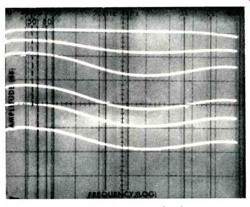
Fig. 9-Response of audio section with loudness switch "on", at various settings of volume control.
The excellent dynamic range capability of the phono section of the AA-1050 was clearly discernible during record listening, both in terms of high signal handling capability and low levels of hum and noise (actually, hum turned out to be lower even than the low random noise generated by the preamp circuit, the converse of what usually occurs in pre amp-equalizer sections). We found that the tape monitoring switch with its separate dubbing positions is a practical way in which to combine both monitoring and dubbing functions in a single, easy-to-use and easy-to-understand rotary control.
While the amplifier section of the Akai AA-1050 may not be the most powerful of any stereo receiver on the market, it is a strong contender for that honor in its price class. Not too many years have passed since the time one would have had to go to a separate amplifier to get this much power.
Distortion remains low at the frequency extremes and is fairly free of higher order harmonics.
The Akai AA-1050 certainly appeals to the eye and to the ear and its price is fully justified by its performance.
Leonard Feldman
===============
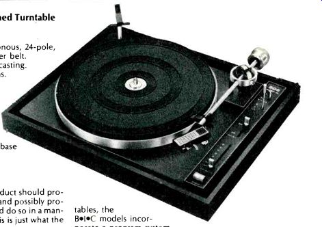
BIC Model 960 Belt-Drive Programmed Turntable
Manufacturer's Specifications
Speeds: 33 1/3 and 45 rpm. Motor: Synchronous, 24-pole, 300 rpm. Drive: Precision ground elastomer belt.
Platter: 12-in. non-ferrous, machined die-casting.
Wow and Flutter: Better than 0.05% w rms.
Rumble: Better than-65 dB DIN. Tone Arm: Tubular aluminum. Length: Pivot to stylus, 216.2 mm (8.51 in.) Weight: 12 lbs. Dimensions: 151/4-in.
W x 12 11/16-in. D (motor board); on base with dust cover, 17 1/16 in.
W x 14 11/16 in. D x 7 in. H; with dust cover raised, 16 H. Price: $159.95; walnut base
$16.95, dust cover, $9.95.
It is only logical that a newly created product should provide all the facilities of previous examples and possibly provide some desirable additional facilities, and do so in a manner which would simplify construction. This is just what the new line of BIC turntables has done.
Readily adjustable stylus force, equally adjustable anti skating settings, cueing control, automatic operation-all these desirable features are present, as they are in most all good turntables. But in addition, the often troublesome idler drive is replaced with a belt drive which reduces the almost direct connection between the motor and the platter, but the motor itself, usually an 1800-rpm device, is here replaced with a synchronous 300-rpm unit, thus reducing the motor's contribution to rumble from 30 Hz to a low 5-Hz signal, which is below audibility.
Fig. 1-Top view of the 960 chassis with the platter removed.
In addition to the features which appear in most turntables, the BI.0 models incorporate a program system which gives the owner seven possible manual and single play automatic options. This feature involves a control knob with the seven operating positions and Off. In the automatic mode, the user simply sets the control lever to the number of records on the spindle, and the unit plays them, returns the arm to its rest, and shuts the motor off. If the manual mode is desired, the user places the control at Man, and the unit plays the one record, returns the tone arm to the rest, and shuts the motor off. If the user wants to play the same record four times, he sets the control to "4," and the record is played the four times, the arm returned, and the motor shut off. This can be done for any number of plays from one to six.
During automatic operation the record which is playing can be rejected and the next one dropped onto the platter by depressing the "cycle" button-an operation which requires a force of less than 100 grams and a travel of only 1/16 in.-so slight a motion and force as not to disturb the tone arm by the jarring common to most turntables.
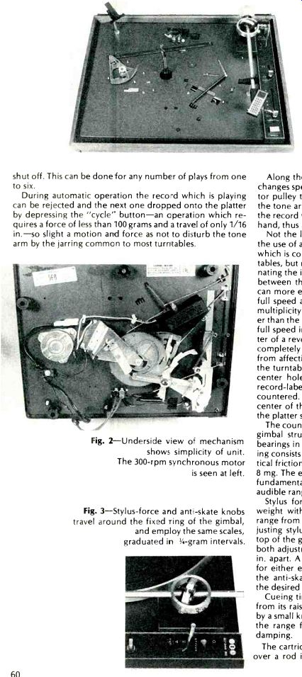
Fig. 2--Underside view off mechanism shows simplicity of unit. The 300-rpm synchronous motor is seen at left.
Fig. 3--Stylus-force and anti-skate knobs travel around the fixed ring of the gimbal, and employ the same scales, graduated in 1-gram intervals.
Along the control panel are also located the lever which changes speed by moving the belt from one level of the motor pulley to another, and the stylus-lift lever, which raises the tone arm for cueing or to permit dropping the stylus to the record with greater precision than can be done easily by hand, thus avoiding possible record scratches.
Not the least of the virtues of the BIK 960 turntable is the use of a 300-rpm synchronous motor and the belt drive, which is commonly used on high-quality transcription turntables, but rarely on automatic models. In addition to eliminating the idler, the belt drive serves to provide an isolation between the motor and the platter so the rotating platter can more effectively act as a flywheel, yet permits reaching full speed at less than of a revolution. Furthermore, the multiplicity of poles-24-provides a smoother flow of power than the usual four-pole design. While the platter reaches full speed in less than a revolution, it stops in about a quarter of a revolution, all of which aids in cueing. The motor is completely shielded to avoid any external magnetic field from affecting the cartridge. A manual spindle rotates with the turntable during manual play, eliminating wear on the center hole of the record and possible drag in cases of record-label extension over the hole as is sometimes encountered. For automatic play, a fixed spindle supports the center of the records, while a platform at the upper left of the platter stabilizes the record stack.
The counterweighted aluminum tone arm is mounted in a gimbal structure with vertical pivots consisting of needle bearings in a hardened ball race and the horizontal mounting consists of a brass shaft resting on a lateral ball race. Vertical friction is less than 5 mg, and horizontal friction is 6-to 8 mg. The effective mass of the tonearm is 18 grams, and its fundamental resonance is from 8 to 9 Hz, again below the audible range.
Stylus force is adjustable-after balancing the counterweight with the stylus-force control set at "0"-over the range from 0-to-4 grams in 1/4-gram steps. The levers for adjusting stylus force and anti-skating are located along the top of the gimbal ring, with the same indications serving for both adjustments, and the 1/4-gram divisions are about 1/16 in. apart. A separate lever on the main control panel is set for either elliptical or conical styli, and the calibrations on the anti-skate control are automatically compensated for the desired stylus.
Cueing time-that period required for the stylus to drop from its raised position to the record surface-is adjustable by a small knob directly in front of the tone-arm mount over the range from 1-to-3 seconds by varying the degree of damping.
The cartridge shell is fitted with a locating hole which fits over a rod in the arm, and with an angle-adjusting screw which permits setting the cartridge at the preferred 15-deg. angle. This is done by a screw in the shell which has an eccentric projection that fits into a hole in the tonearm head.
The screw nay be turned with a small screwdriver to achieve the desired angle when the nut which secures the shell to the arm is loosened. In addition, to compensate between the angle offered by the cartridge when playing a single record or a stack of six records, a slide in the top of the shell is moved to the M or A positions (for manual or automatic), resulting in a slight shift in the cartridge position in the shell.
The electrical connection between the shell and the arm is made by a 4-pin plug on the arm which engages a socket in the cartridge shell. This ensures a noise-free connector which is not likely to develop the problems often resulting from the sliding contacts commonly used in cartridge shells.
A generously sized, stainless-steel finger lift completes the shell's features. A rest provided on the main chassis serves to accommodate the arm during normal operation, and to hold the arm firmly when the tone arm lock is engaged for transporting or moving the turntable. Two wing nuts hold the entire chassis firmly to the base during any transporting of the unit, but in normal operation the wing nuts are loosened permitting the chassis to float on its four elastomeric mounts.
Two molded projections are located at the rear of the base and when the smoked lucite dust cover is placed in position, they serve as a hinge point for raising the cover, which will remain in the raised position with no screws, bolts, or other connecting devices. There are two optional bases available-one of oiled walnut, and another of molded plastic with a matte finish. Both have the safety/hazard transparent bottom cover.
The chassis is extremely compact extending only 1 5/8 in. below the mounting board, and 4 15/16 in. above with the multiple-play spindle in place, or a total of 6 9/16 in. above the surface on which the turntable rests. With the dust cover in place, the overall height is 6 7/8 in., or with the dust cover raised, 16 in.
The paired audio output cable appears to be of the same size as a typical a.c. cord, but in reality it is a low capacitance cable, resulting from an extremely fine center conductor within the shield, with a capacitance of 20 pF/ft., thus being compatible with CD-4 cartridges.
The 980 model is essentially identical with the 960, but is fitted with a solid-state electronic drive and speed control which furnishes the drive power to the motor in place of the usual a.c. line supply. Its frequency, generated by a Wienbridge oscillator, can be varied ±3% from the usual 60 Hz, resulting in an adjustable speed over the same range. A control knob located at the left front of the chassis controls this frequency, and the neon stroboscope light, illuminated by line frequency, shows when the speed is adjusted to the normal value. The stroboscope is viewed through an opening in the chassis by way of a built-in angled mirror. It's price is $199.95 with base and cover the same.
Performance
With its compactness, appearance, wide range of adjust ability and its many other features, how does the 960 perform? That is the crucial question.
Simply stated, its performance provides the user with a simple, yet effective means for handling records-either singly or in a stack. The programming feature permits playing a stack through and then stopping the unit with a much simpler mechanism than is required for the more conventional types. And, of course, it is generally accepted that belt drives are freer of wow and flutter than most other types-with the exception of the expensive direct-drive units, and even with some of these we have encountered a form of flutter which shows up instantly if the platter is removed, thus eliminating the flywheel effect of the platter's Wow and flutter were measured separately, with the former measuring 0.04%-this resulting from measurement of frequencies below 6 Hz-and flutter-frequencies between 6 and 250 Hz-at 0.03%, and a total over the range from 0-to-250 Hz measuring 0.05%. Range of speed control on Model 980 was measured by reproducing a 1000-Hz record and feeding the output to a counter, with the range extending from 967 Hz to 1031 Hz, or just slightly over ±3%. Model 960, with no means of varying speed, reproduced the 1000-Hz tone at 1001 Hz.
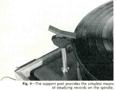
Fig. 4--The support post provides the simplest means of steadying records on the spindle.
Rumble, which is probably the most important figure in any report on a turntable, measured 48 dB below the standard level of 3.54 cm/sec at 1000 Hz. Converted to normally reported figures, this means a rumble figure of-66 dB, since rumble measured on a flat system is generally accepted as being 18-to-20 dB lower than the acoustically perceived level. This is borne out by using the DIN test record No. 45544, "Rumpel-mess-schallplatte," and the specified measuring techniques, which produced a figure of-64 dB. Cycling time for 331/3-rpm records was measured at 15 seconds, with the cueing adjusted for a 3-second delay. Speeding up the cueing delay reduced the cycling time to 13 seconds.
On the whole, the BIC 960 and 980 turntables appear to provide everything a critical user could want, and at prices which do not create too large a dent in the budget. The measured performance certainly places these machines in the superior category, while their thoughtful designwork makes them easy to operate.
C. G. McProud
===============
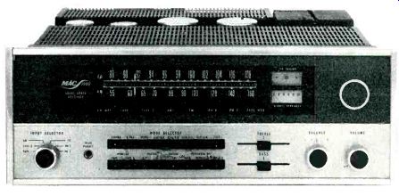
McIntosh MAC-1900 AM-FM/Stereo FM Receiver
MANUFACTURER'S PUBLISHED SPECIFICATIONS
FM Tuner Section
IHF Usable Sensitivity: 2.5 µV (13.4 dBf), mono. S/N Ratio: 70 dB, Mono.
THD: Mono, 0.3%; stereo, 0.7%. Capture Ratio: 1.8 dB. Selectivity: 55 dB. Spurious Rejection: 90 dB. Image Rejection: LIC dB. Stereo Separation: 34 dB (at 1 kHz). Frequency Response: 20 Hz to 15 kHz ±1 dB. AM Tuner Section Sensitivity: 75 µV, external antenna.
S/N Ratio: 45 dB. THD: 1.0 : 30 dB.
Image Rejection: 65 dB.
Frequency Response:-6 dB at 3500 Hz.
Preamplifier/Control Section Input Sensitivity: Phono 1 & 2, 2.0 mV; Tape 1 & 2, 250 mV. Hum and Noise: Phono 1 & 2, 76 dB below 10 mV referenced input; Tape 1 & 2, 90 dB below rated output. Bass Control Range: ±16 dB at 20 Hz. Treble Control Range: ±16 dB at 20 kHz. Low Filter : -18 dB at 20 Hz, 12 dB/octave slope. High Filter: -18 dB at 20 kHz, 12 dB/octave slope.
Power Amplifier Section
Power Output: 55 watts per channel, continuous power, into 8 ohms, at any frequency from 20 Hz to 20 kHz with no more than 0.2% total harmonic distortion; 40 watts into 4 ohms and 30 watts into 16 ohms, all other conditions remaining the same. All ratings with both channels driven. IM Distortion: 0.2% for any combination of frequencies between 20 Hz and 20 kHz. Hum and Noise: 95 dB below rated output. Damping Factor: 56 at 8 ohms.
General Specifications Dimensions: 16 in. W x 5 '/ in H x 15 in. D. Weight: 33 lbs.
Suggested Price: $949.50.
It was 1965 when Audio Magazine last published a test report dealing with a piece of McIntosh high fidelity equipment. Certainly, this omission was not prompted by any desire on our part to ignore the products of that highly reputed manufacturer whose products have been well received by loyal purchasers since 1949. The fact that McIntosh Laboratories, Inc., has been able to survive and prosper in an era of fierce competition and intense advertising and promotion is in itself ample testimony to the power of word-of-mouth advertising. McIntosh owners, fiercely loyal to the product and the company, have on many occasions accused this and other publications of deliberately ignoring that firm's products because of their policy of limited advertising in this and other hi-fi publications.
What few readers realize is that the conspicuous absence of McIntosh test reports in these pages over the last several years was primarily due to McIntosh's own reluctance to permit "less than qualified" test reviewers to "measure" the equipment on "less than professional" laboratory equipment. We are happy to report that, after representatives of the company had an opportunity to examine our test facilities, they have reversed their earlier decision and, from time to time, we hope to make up for their overly long absence from these pages.
The MAC-1900 tested for this report is not a new product.
It has been in production for some six or seven years, and we were therefore particularly anxious to see how it would "stand up" against more recently designed receivers.
The ruggedly designed black and gold front panel extends beyond the chassis width and height, making custom installation simple; the MAC-1900 is normally supplied less wooden enclosure. FM, AM and logging scales, plus twin tuning meters in the dial area, are augmented by a series of illuminated rectangular areas below, which denote program source selected, tape monitor circuit activation, and stereo FM reception. A large tuning knob to the right of the dial area is coupled to a smooth and effective flywheel, dial string, and pointer combination. The pointer center is brightly illuminated.
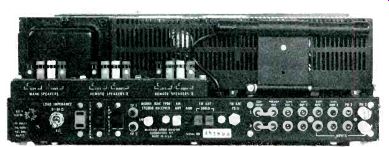
Fig. 1-Back panel.
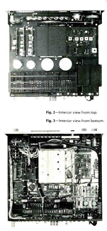
Fig. 2-Interior view from top.
Fig. 3-Interior view from bottom
The lower section of the front panel includes a six-position input selector switch and rotary balance and volume controls. The counterclockwise position of the volume control turns off power to the entire receiver. Horizontally oriented linear slide controls take care of bass and treble adjustment, and a slight detent in each slide helps locate mid position for flat response. Two banks of pushbuttons handle all other control features. The upper bank of eight buttons handles a variety of reproduction modes including: stereo, reverse, channel source to both speakers, combined channels to any single speaker, and mono. A loudness switch completes this row of buttons. The lower bank of pushbuttons selects high and low filters, either or both tape monitor circuits, FM muting, and up to three separate pairs of loudspeakers which might be connected to the receiver. With speaker buttons in the Out position, sound is heard from the appropriate set of speakers, so that to turn any or all sets of speakers Off it is necessary to depress one or more buttons in this group.
The rear panel of the MAC-1900 is pictured in Fig. 1. All speaker connection terminals are mounted upright, which makes connection very easy since stripped speaker-wire ends are simply inserted in the spring-loaded, push-button terminals horizontally, as the speaker cables would normally be dressed. Care must be taken, however, not to strip and insert too great a length of wire which might project through to the opposite side of the terminal and make contact with metallic structures on the topside of the chassis.
The rear panel of the chassis contains three convenience a.c. outlets, two pairs of phono inputs, two sets of Tape Out and Tape Monitor (high level) inputs, antenna terminals for connection of external AM, 300-ohm FM or 75-ohm FM antenna transmission lines, a chassis ground terminal, and a pair of jumpers which connect between Preamp Out and Main Amp In jacks. Jumpers can be removed for independent use of these two sections of the receiver. A pair of jacks labeled TP-1 and TP-2 are intended for connection of McIntosh's Maximum Performance Indicator, a special scope/meter product sold by McIntosh that is useful in testing and evaluating audio system performance. A power line fuse and a pivotable AM ferrite bar antenna complete the rear panel layout.
The MAC-1900 is supplied less wooden enclosure but all components are fully shielded and enclosed in black finished metal covers, two of which were removed for the photo of Fig. 2 which is a top view of the chassis layout. The fully shielded r.f. front-end can be seen centered in the chassis with the i.f. section to the right and three of the many circuit boards vertically mounted at the left. A view of the underside of the chassis is shown in Fig. 3 and the orderly harnessed wiring is clearly discernible, as are additional circuit modules.
Circuit Highlights Two stages of r.f. amplification (one a dual-gate MOS-FET, the other a JFET) are used in the FM r.f. section, and tuning is accomplished by means of a four-section variable capacitor (three additional ganged sections handle AM tuning). The mixer also uses a JFET, while the local oscillator is a bi-polar device. A monolithic silicon differential/cascode amplifier, in the form of an IC, serves as the first i.f. amplifier stage and is located within the r.f. housing. The FM i.f. section uses two additional IC's and two quad-tuned, link-coupled filters for a total i.f. gain of over 120 dB. Filters are sealed and require no realignment. A true Foster-Seeley discriminator is used as an FM detector. (Seeing it was like meeting an old reliable friend after an absence of several years.) The stereo decoder section of the receiver is fairly conventional in design and employs a bridge-type switching demodulator.
Special attention is paid to SCA filtering.
The AM section, in addition to employing a separate r.f.
amplifier and two i.f. stages, incorporates a 10-kHz adjacent channel filter (another nicety that has been "overlooked" in so many receivers where AM is designed in pretty much as an afterthought). The phono-equalizer sections use three transistors per channel for the 42-dB mid-band gain required, so that feedback is applied even at 20 Hz where maximum bass boost is required by RIAA playback curves. A differential amplifier is used at the high-level input stages, and tone controls are of the familiar negative feedback type. Tone controls and associated components are mounted on a double-sided plated through printed circuit board.
The power amplifier sections also use a differential input stage, one input of which is the negative feedback voltage from the power output stages. The output section is a direct coupled, series push-pull amplifier. Circuit protection is afforded based first upon temperature of output transistor cases (a sensing device turns off a.c. in the event of thermal problems) and by McIntosh's Sentry Monitoring Circuit, which restricts drive to the output stages if power dissipation exceeds safe limits because of excessive mismatching or shorting of the outputs. Output signals are direct coupled, thanks to the dual polarity 40-volt supplies. An additional supply powers the driver stages, while two more regulated voltage supplies handle tuner and preamp stages.
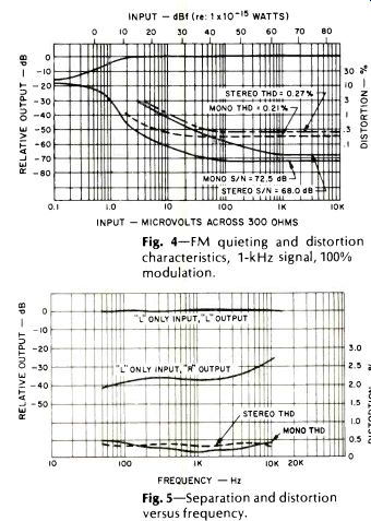
Fig. 4-FM quieting and distortion characteristics, 1-kHz signal, 100% modulation.
Fig. 5-Separation versus frequency. 10K 20K and distortion
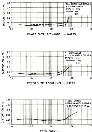
Fig. 6-Harmonic and intermodulation distortion characteristics with 8-ohm loads.
Fig. 7-Harmonic and intermodulation distortion characteristics with 4-ohm loads.
Fig. 8-Harmonic distortion versus frequency.
FM Performance Measurements
Although McIntosh has modified its specification sheet to fully conform with the new FTC rule on power output disclosures, their statements regarding FM performance have not been up-dated to reflect requirements of the new IHF/IEEE tuner measurements standards. For example, signal strength figures are only quoted in microvolts (instead of dBf), and many of the new required stereo performance figures are absent. As we soon learned, these omissions are not the result of inadequate performance in these areas. Usable mono sensitivity, guaranteed to be better than 2.5 µV (13.4 dBf)--all McIntosh specs are stated as "limits" which every set is guaranteed to make or better-actually measured 2.0 (11.4 dBf). Stereo usable sensitivity (not quoted by the manufacturer) turned out to be an excellent 3.0 µV (14.9 dBf). The 50-dB quieting level in mono was reached with an input signal strength of 3.0 µV (14.9 dBf), while in stereo the signal strength required for this degree of quieting was an impressively low 25 µV (33.4 dBf). Best signal-to-noise ratio in mono reached 72.5 dB, passing the 70-dB mark at just under 50 µV (39.4 dBf), while in stereo best S/N was 68 dB. Quieting and distortion characteristics for a 1-kHz signal in mono and stereo at 100% modulation are graphed in Fig. 4.
THD in mono reached a low of 0.21%, while in stereo THD was almost as low, with a reading of 0.27%. Stereo separation, while not as great as in some more modern receivers which use phase-lock-loop MPX circuitry, exceeded mid-band specs and measured 37 dB at 1 kHz.
Separation and mono and stereo distortion at other frequencies are plotted in the graphs of Fig. 5.
The single failing that we noted in the stereo section of the Mac 1900 was its poor rejection of sub-carrier products at the tape output (and even at the speaker output) terminals. Such high frequency output components were down about 35 dB at the tape output terminals and might cause problems when recording FM stereo programs "off the air" on tape decks not equipped with separate MPX filters, especially when Dolby encoding is used. On the other hand, 75 microsecond de-emphasis was just about perfect all the way out to 15,000 Hz-a situation very seldom encountered on tuners and receivers which sharply filter out 19-kHz and 38 kHz residual products.
Other performance measurements all turned out to be better than published specs as well, with capture ratio reading 1.5 dB, alternate channel selectivity readings of 62 dB, image rejection of 83 dB, and spurious response rejection in excess of 100 dB-the limit of our measuring capability.
Amplifier/Preamplifier Measurements
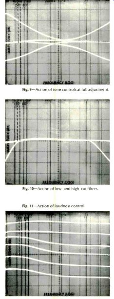
Fig. 9--Action of tone controls at full adjustment.
Fig.10--Action of low- and high-cut filters.
Fig. 11--Action of loudness control.
Figure 6 is a plot of distortion versus power output per channel with power delivered to 8-ohm loads. McIntosh's conservative ratings are even more apparent in the amplifier and preamplifier sections of this receiver than in the tuner section. Some 66 watts per channel was delivered by the amplifier before rated THD of 0.2% was reached. At Mac's rated output of 55 watts per channel, THD was still a mere 0.035%, while IM distortion measured just under 0.1% for that level of power output, reaching its rated value of 0.2% for 70 watts per channel of output power.
McIntosh is one of the few manufacturers which has continued to offer a 4-ohm power output rating in this era of FTC amplifier power regulations. In an addendum sheet supplied with the owner's manual, power output into 4-ohm loads is listed at 40 watts per channel. While this may seem contradictory to the laws of physics (nearly all solid-state amplifiers deliver greater power into 4-ohm loads than into 8 ohms), one must remember that the FTC power rule (specifically, the preconditioning requirement) places severe thermal limitations on amplifiers which might actually be expected to deliver much more power under musical or short-term high-power listening conditions. That, in fact, is just what happens if one measures the Mac 1900 at 4 ohms without regard to the one hour preconditioning requirement. It then delivers 72 watts per channel at mid-frequencies and not much less at the frequency extremes before reaching the 0.2% THD point. Power versus THD and IM for 4-ohm load conditions is plotted in Fig. 7. Figure 8 is a graph of THD versus frequency for a constant 55-watt output level per channel into 8-ohm loads. At the 20 Hz extreme, THD is still a very low 0.054%, while at 20 kHz THD reaches 0.13%--still well below the 0.2% nominal THD rating. At the 55-watt output rating, McIntosh could well have specified the power band as extending all the way from 16 Hz to 28 kHz had they been willing to "push" the published specs as far as some other manufacturers.
As for the preamplifier and control sections of the Mac 1900, we measured an input sensitivity for both sets of phono inputs of exactly 2.0 mV, as claimed. Phono overload at 1 kHz occurred at an input level of 110 mV (not the highest we have ever recorded, but certainly high enough for all practical purposes). Hum and noise in phono, referred to actual 2.0 mV input sensitivity was an amazingly high 72 dB. Translated to a 10 mV input reference, the figure becomes an incredible 86 dB! RIAA equalization was accurate to within 0.5 dB from just under 100 Hz to 15,000 Hz but was off by about 2 dB at the 30 Hz frequency extreme.
Bass and Treble control range is depicted in the sweep frequency plots of Fig. 9, while the precise characteristics of the low- and high-cut filters are similarly plotted in the 'scope photo of Fig. 10. Loudness control action, in 10-dB increments beginning from full clockwise rotation of the volume control, is depicted in the sequential traces of the storage 'scope photo in Fig. 11. Hum and noise measured via the high-level (tape) inputs of the MAC 1900 measured 92 dB, while residual power amplifier noise and hum was 96 dB referred to full power output.
Listening and Use Tests
One can argue about the importance of "super-low" distortion, ultra wide-band frequency response (the MAC-1900 rolls off 3 dB at 8 Hz and 45 kHz), ultra high damping factors (the MAC 1900 has a damping factor of 56 at 8 ohms), and the need for super-high phono overload capability all day long, but the proof, after all, is in the listening. And the MAC-1900 "listens" extremely well. Bass is tight and well defined and, rated power notwithstanding, we were able to drive several low-efficiency speaker systems (which are reputed to require higher input power than the MAC-1900 provides) to bigger-than-life sound pressure levels with no audible evidence of amplifier clipping or other forms of audio misbehavior. In terms of absolutes, the FM tuner section does not measure as well in many respects as do some of today's brand new tuners and receivers, but then again we come back to the question of program sources available from FM stations, the majority of which are far poorer than the inherent performance capability of the tuner section of this relatively "old" McIntosh design. We should note, by the way, that the AM tuner section of this receiver is extremely well designed for its time or even in terms of what is generally provided as an AM section on most of today's competitive AM/FM receivers.
All of which brings us to the suggested retail price of the MAC-1900, which seems, at first glance to be out of line if measured on a watts/dollar basis. Talk to any Mac equipment owner, however, and you will rarely hear a complaint about the high initial cost of McIntosh equipment. The Mac loyalists inevitably end up talking about long-term reliability, quality of parts used in construction (we heartily concur here), absence of service problems and "down time," and total willingness of the company and its selected dealers to render prompt and complete service if the need ever does arise. These components of the "McIntosh Mystique" are hard to translate into dollars and cents, to be sure, but sufficient numbers of Mac enthusiasts have been able to justify initial costs of McIntosh equipment to make that company one of the longest lived and highly respected in the United States and abroad.
Leonard Feldman
(Audio magazine, 1976)
Also see:
Audio In General (Depts) (June 1976)
Energy-Time Test/Richard C. Heyser
Making Records/Ralph Cushino
= = = =