
MANUFACTURER'S SPECIFICATIONS
FM Tuner Section
Usable Sensitivity: 10.8 dBf (1.9 µV), Mono.
50-dB Quieting: Mono, 16.2 dBf (3.5 µV); Stereo, 37.3 dBf (40 µV).
S/N: Mono, 76 dB; Stereo, 74 dB.
Stereo Threshold: 28.8 dBf (15 µV).
Muting Threshold: 20.8 d Bf (6 µV).
Frequency Response: 30 Hz to 15 kHz, +1,-2 dB.
Distortion @ 50-dB Quieting: Mono, 0.6 percent; Stereo, 0.9 percent.
THD @ 65 dBf; Mono, 0.4 percent; Stereo, 0.5 percent.
Capture Ratio: 1.5 dB.
Adjacent Channel Selectivity: 10 dB
Alternate Channel Selectivity: 80 dB
I.f. Rejection: 100 d B.
AM Suppression: 65 dB.
Image Rejection: 100 dB.
Spurious Rejection: 100 dB.
Stereo Separation: 100 Hz to 10 kHz, 40 dB.
38-kHz Suppression: 55 dB.
Power Amplifier Section
Power Output: 40 watts average continuous per channel, 8 ohm loads, 20 Hz to 20 kHz.
Rated THD: 0.09 percent.
Rated IMD: 0.09 percent.
Damping Factor: 50 at 8 ohms.
S/N @ Min. Volume: 86 dB, unweighted.
Preamplifier Control Section
Input Sensitivity: Phono, 2.8 mV; Tape, 190 mV.
Phono Overload: 90 mV.
S/N: Phono, unweighted, 66 dB re: rated input; Tape, 82 dB.
Frequency Response: 8 Hz to 50 kHz, -1.5 dB.
Bass & Treble Control Range: ±15 dB @50 Hz and 10 kHz.
Low& High-Filter Cutoffs: -3 dB @ 70 Hz & 8 kHz, at 12 dB/octave.
General Specifications
A.C. Power Requirements: 120/220/240 V, 50/60 Hz, 270 W (at full power).
Dimensions: (51 cm) W x (14.3 cm) H (30 cm) D.
Weight: 21 lbs. (9.53 kg).
Price: $565.00.
--------------
Every time we have occasion to unpack a Tandberg receiver (or any other of their products, for that matter), we are impressed by the ultra-clean design of the front panel, its logically arranged controls, and the distinct feeling of elegance that it exudes. The TR-2040 is no exception and is configured much like the earlier (and lower powered) TR-2025. The softly illuminated blue dial area is linearly calibrated every 0.5 MHz, and there is a channel-number scale as well (though few American users know that FM channels are assigned sequential numbers). To the right of the scale are signal-strength and center-of-channel tuning meters, also illuminated for easy visibility. The light-colored section of the panel, below the dial area, contains the major controls which include a rectangle-shaped power On/Off push button; rotary master volume, balance, bass, treble and tuning controls; two tape monitor switches; a phono selector switch; the FM pushbutton, and five more rectangular buttons labeled P1 through P5 for selecting preset stations. Tuning in these favorite stations is accomplished by means of tiny rotary controls just below each of the five preselect buttons. When these buttons are used, the signal-strength meter becomes an approximate-frequency indicator while the center-of-channel meter continues to aid in precision tuning. At the very bottom of the panel and to the left of the preset potentiometers are a phone jack, muting pushbutton, stereo-mono switch, low- and high-filter switches, speaker selector buttons (up to two pairs of speakers can be connected to the TR-2040), and a loudness button.
Connections on the rear panel of the unit caused us a few problems. While conventional screw terminals are provided for the external FM antenna connection (either 300-ohm or 75 ohm coaxial), all other connections require special multi-pin plugs-DIN type for the phono input and tape out/tape in connections and polarized plugs for speaker connections. We quickly discovered the latter plugs in a separate envelope but were a bit distressed at the microscopic hole through which one is supposed to thread the "hot" speaker leads. If, as we have all been preaching, one should use heavy-gauge speaker wires with good equipment, a user is likely to have problems trying to squeeze all the strands of an 18-gauge wire into this tiny hole provided in the accessory plugs. We also found adapter cables for the phono and tape sockets and had no trouble hooking up the phono inputs. The adapter for the tape DIN connector, however, had its pins so far recessed in to the shell of the connector that there was no way we could make contact to the female counterpart on the rear panel, since the shell of the adapter plug was stopped by the rear surface of the chassis itself. While we were able to come up with properly fitting DIN connectors from our stock of cables, we would like to see Tandberg pay just a bit more attention to what can be a terribly aggravating problem.
Happily, that is the complete extent of our criticism of the layout and engineering of this beautifully crafted set. As always, removal of the cabinet sections is easy, and complete access for servicing is gained once the cabinet sections are set aside. Most of the circuitry is p.c. board mounted, and all shielded cabling coming from controls and the like terminates in positive fitting plugs which pop onto clearly labeled terminals at various points on the p.c. board surface.
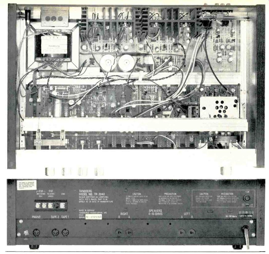

Power heat sinks are vertically mounted towards the center rear of the chassis and seemed adequate for the power levels of which the TR-2040 is capable. Power transformer and other power supply parts are about as far away from low-level signal circuits as they could be, and the layout is in all ways typical of Tandberg quality. No schematic was provided with the unit, so we cannot comment regarding actual circuitry used except to note that varactor tuning is employed in order to provide those preset station settings. The "tuning" controls are nothing more than potentiometers of high precision which pick off the proper voltage to apply to the capacitor like varactor diodes.
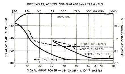
Fig. 1--Mono and stereo quieting and distortion characteristics in the FM
section.
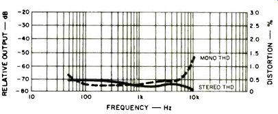
Fig. 2--Distortion vs. frequency.
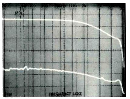
Fig. 3--FM frequency response and stereo separation, including 75 µS de-emphasis.
(Vertical scale is 10 dB per division.)
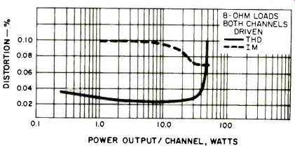
Fig. 4--Distortion vs. power output.
FM Tuner Section Measurements
We should emphasize what a reading of the manufacturer's published specifications already highlights. Tandberg has gone all out to comply with every last tuner specification called for in the new IEEE/IHF Tuner Measurement Standards. Furthermore, that company's penchant for conservatism in ratings holds true for this receiver. The 50-dB quieting point was attained with a signal input of only 14.74 dBf (3.0 µV across 300 ohms) in mono and 36.1 dBf (35 µV) for stereo. Best signal to noise in mono was 74 dB; 71 dB in stereo (both a bit short of claims, but certainly high enough to qualify as among the best). At 1 kHz, THD in mono measured 0.26 percent, well below the 0.4 percent claimed, while in stereo the THD for a 1-kHz signal was just as good, 0.26 percent against 0.5 percent claimed. Quieting and distortion characteristics in mono and stereo are plotted in the graphs of Fig. 1. Figure 2, a plot of frequency versus distortion in FM, discloses that at all but the 10-kHz test point, THD is almost as low in stereo as it is in mono. At the low-frequency end of the spectrum, it actually proved to be somewhat lower. The sudden rise in THD at 10 kHz in stereo is really more a function of stereo "beats" showing up than of true harmonic distortion.
Separation measured 47 dB at 1 kHz, 40 dB at 100 Hz, and 32 dB at 10 kHz. A complete plot of frequency response (including the 75 microsecond de-emphasis roll-off) and separation is shown in the spectrum analyzer 'scope photo of Fig. 3. Accurate design of the 19-kHz notch filter (note the slight rise at 15 kHz) accounts for the excellent response all the way out to 15 kHz which was down only 0.5 dB as against 2.0 dB allowed in the specs. Other FM section measurements made included a capture ratio reading of 1.3 dB, alternate channel selectivity of 83 dB, and AM suppression of 65 dB, better than or exactly as claimed. We measured 100 dB for image, i.f., and spurious rejection as claimed, but since that is the limit of our test equipment, one or more of these figures may actually be higher. Muting threshold was set a bit higher than claimed, at 10 µV (25.2 dBf), while stereo threshold measured 17 µV (29.8 dBf). Center-of-channel indications on the tuning meter corresponded exactly with lowest distortion tuning points as observed on our distortion analyzer, a good indication of the care that had been exercised by the factory during final alignment of the receiver.
Power Amplifier Section Measurements
At mid frequencies, the TR-2040 delivered 50 watts per channel into 8-ohm loads with both channels driven to its rated THD of 0.09 percent. At that same output, IMD measured 0.07 percent. Strangely, however, the IMD increased slightly at lower power output levels, though not enough to be audible under any musical listening conditions. Results of IM and THD measurements versus power output are shown in Fig. 4. Distortion at actual rated output (40 watts per channel) was a very low 0.029 percent for 1 kHz, increasing to 0.04 percent at 20 Hz and 0.05 percent at 20 kHz, as shown in the graph of Fig. 5. Damping factor measured 50 at mid frequencies, as claimed. Full power for rated THD was obtained over the frequency limits of from 17 Hz to 33 kHz. If one were to rate the unit on the basis of FTC rules from 20 Hz to 20 kHz, it would qualify for a 41.4 watt rating as opposed to the 40 watts per channel claimed.
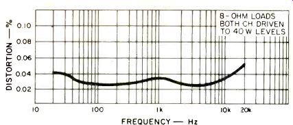
Fig. 5--Distortion vs. frequency with 8-ohm loads, both channels driven
to 40-W levels.
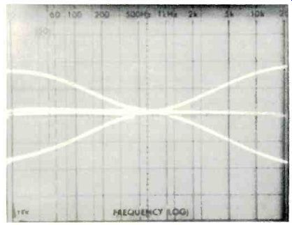
Fig. 6--Bass and treble control range. (Vertical scale is 10 dB per division.)
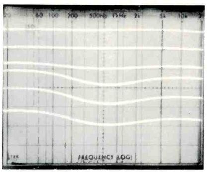
Fig. 7--Loudness control action in 10-dB increments of master volume control.
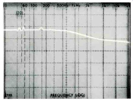
Fig. 8--Equalized RIAA phono response. (Vertical scale is 2 dB per division.)
Preamplifier and Control Section Measurements
The tone controls of the TR-2040 offer perhaps more range than will be needed for most applications, greater than ±15 dB at 50 Hz and 10 kHz, as illustrated in the spectrum analyzer scope photo of Fig. 6. We suggest, therefore, that users of this receiver not arbitrarily crank these controls up to maximum boost positions (something that a great many neophytes still tend to do), since doing so might well overload the amplifier, even at nominal listening levels. When set to their flat positions (by eye, as there are no detents on the tone controls), overall response from the tape inputs to speaker outputs was flat, within 1 dB from 8 Hz to 50 kHz. The 3-dB down points occurred at 6 Hz and 80 kHz. Since there is no AUX input pair on this receiver, all high-level measurements were made using the tape playback input, which required depressing the appropriate tape monitor button on the front panel. Via those inputs, high-level sensitivity was 190 millivolts for rated output. Signal to noise via the high level inputs measured 93 dB (unweighted), referred to rated input sensitivity and rated output. Loudness control action is depicted in the graphs of Fig. 7.
Phono input sensitivity measured 3.2 millivolts for rated output, and signals levels of up to 100 millivolts were handled by the phono preamplifier section (at 1 kHz) with no evidence of overload distortion. Signal-to-noise ratio in phono mode measured 72.5 dB, again referred to actual input sensitivity levels. The RIAA playback curve was plotted using an inverse RIAA characteristic as results are shown in the spectrum analyzer scope photo of Fig. 8. Note, that in this presentation, the vertical scale has been magnified to 2 dB per division.
Nevertheless, the dip in response above 1 kHz amounts to a bit more than 1.5 dB at the high-frequency extreme-a little high for a set of this overall quality. We found that a slight rotation of the treble control to the " 1 o'clock" position corrected this discrepancy almost perfectly out to 15 kHz.
Listening and Use Tests
The Tandberg TR-2040 is one of those special receivers which can neither be judged by power output nor price alone. Evaluated on a pure watts/per dollar basis, the cost seems fairly reasonable. Listened to without regard to price or power, one comes away convinced that this Scandinavian company knows something about high-fidelity sound reproduction and human engineering that many other firms seem to have missed somewhere along the line. One is not as conscious of the equipment as one is of the music, which is totally devoid of what one might call electronic coloration.
Surprisingly high sound levels are achieved with no evidence of overload or amplifier clipping-further proof that the continuous power rating of an amplifier tells little about how "loudly" it will reproduce musical signals. We might have preferred just a bit more gain in the phono section (to match FM levels without having to readjust the volume setting when switching from one program source to the other) but there was ample reserve on the master volume control to take care of this minor matter. A higher output cartridge would probably take care of this problem too (ours had an output of 2.0 mV for 3.54 cm/sec. velocity), but we would not recommend an overly hot cartridge for this unit because its overload reserve, though adequate, is not huge.
Hum and noise perceived during listening tests were both so low as to be totally unobtrusive, even during quietest recording passages on the direct-to-disc records we now use for auditioning all phono circuits of products we test. Transients in music are reproduced effortlessly by this receiver, while bass is tight and well defined. We seemed better able to single out specific musical instruments in orchestral works than we are typically able to do with most receivers in this power class. All in all, the Scandinavian alternative of which Tandberg speaks in some of its advertising is truly an alternative worth very serious consideration.
-Leonard Feldman
(Adapted from: Audio magazine, Jun 1978)
Also see:
Tandberg Model TR-1055 FM/AM Stereo Receiver (Jul. 1974)
Tandberg TR 1020 Receiver (Feb. 1973)
Tandberg 3080A FM Receiver (Equip. Profile, July 1989)
Tandberg Compact Disc Player (Nov. 1987)
Tandberg TCA 3018A Preamp and TPA 3026A Amp (Apr. 1987)
Tandberg 3008A Preamp and 3009A Amp (Jan. 1986)
= = = =