MANUFACTURER'S SPECIFICATIONS
FM TUNER SECTION: IHF Sensitivity: 2.0 uV (1.6 uV typical). S/N: mono, 68 dB; stereo, 66 dB. THD: Mono, 0.2%; Stereo, 0.3%. Selectivity: 80 dB. Capture Ratio: 0.9 dB. Frequency Response: 20Hz to 15,000 Hz (-3 dB). Separation: 40 dB.
AM TUNER SECTION: IHF Sensitivity: 600 µV /Meter (internal antenna); 60 µV (external antenna). Selectivity: 45 dB. IF Rejection: 52 dB. Image Rejection: 39 dB. THD: 1.0%.
AMPLIFIER SECTION: Power Output: 55 watts/channel, 8 ohm loads, both channels driven, any frequency from 20 Hz to 20 kHz. THD: 0.2%. IM: 0.2%. Power Bandwidth: 4 Hz to 40 kHz. Damping Factor: (1 kHz): 55; (20 to 20,000Hz): 50. Frequency Response: 7 to 70,000 Hz,-1.5 dB. Input Sensitivity: Phono, adjustable from 2 mV to 8 mV; Tape 1 and 2, adjustable from 150 to 600 mV. Phono Overload: 100 mV. Preamp Output Level: 2.0 V. Main-amp Input Level: 220 mV.
GENERAL SPECIFICATIONS: Dimensions: 17 in. W x 41/4 in. H x 12 in. D.
Weight: 23 lbs.
Price: $579.90 (cabinet included).
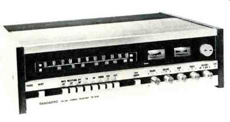
The Tandberg Model TR-1055 is more than just a worthy addition to that company's line of receivers which began with the TR-1020 reviewed here more than a year ago. It is a superb product in every sense of the word and is NOT just a higher powered version of the earlier entry. The sole criticism you will find in this entire review has to do with the listed specifications presented by this reputable manufacturer from Norway--and that is a two-fold criticism. First, the company failed to give us enough specifications, omitting such important numbers from their instruction booklet as AM suppression, Spurious Response Rejection, Image Rejection and IF Rejection. Since all of these parameters turned out to be excellent, Tandberg could have done themselves a lot of good by being more complete in their tabulation of performance specifications.
Second, those specifications that are listed are almost without exception too conservative for the highly competitive U.S. market where manufacturers tend to squeeze every last watt and microvolt (and then some) out of their products! Seriously, though, the TR-1055 is a handsome receiver--inside and out, and resembles the earlier TR-1020 in panel layout and execution. Clean aluminum extruded bars break up the long expanse of panel into easy-to-use and read sections, with a well illuminated AM and FM dial scale, a signal strength and center-of-channel meter and a large tuning knob occupying the upper section. Below the meter area are a series of illuminated words which light up to tell you mode of operation and presence or absence of such extra circuits as filters and loudness control in the audio chain. The center "bar" is legibly and boldly marked with the names and functions of the pushbuttons and rotary controls located directly below. These include a power on/off switch, muting switch, stereo/mono FM switch, five program selection buttons (FM, AM, Phono, Tape 1 and Tape 2), tape monitor button and volume, balance, bass, treble and speaker selector in the form of easy to grip rotary knobs. This row also contains the usual phone jack and a "Tape 3" jack which, besides enabling you to connect a tape recorder directly via the front panel is special in another way.
The lower bar of aluminum which looks for all the world like an immovable part of the front panel is in reality a hinged flap which, when pulled down reveals such secondary controls as a mono/stereo selector, a mono-L(eft) selector, mono-R(ight) selector, rumble filter switch, loudness control switch, a pair of high-frequency filters and a unique pre-amp record button which allows you to use the aforementioned Tape 3 jack without bypassing tone, volume, balance and filter controls for altering the tonal response of the recording in process. We honestly can't think of a single control facility that Tandberg might have added to this panel-and yet, when that flap is swung back into place, the Tandberg TR-1055 looks uncluttered, clean and elegant. Incidentally, in case the flap is closed and you're not sure of how the Tape 3 jack is in the circuit (bypassing controls or not) a light in the dial area lets you know that at a glance too.
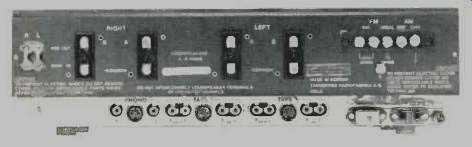
Fig. 1--Rear panel.
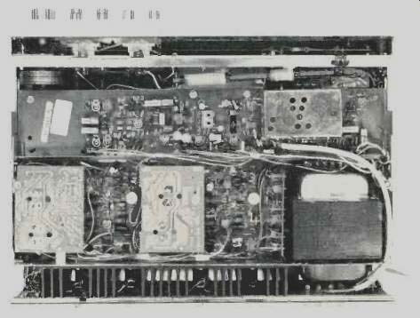
Fig. 2--View of the chassis.
The rear panel of the TR-1055, pictured in Fig. 1, contains conventional phono tip input and tape output jacks, with each pair of jacks supplemented by a standard DIN socket. Speaker connections for two sets of stereo speakers also provide a dual option-regular screw terminals or polarized sockets. By connecting corresponding plugs to your speaker cables you are assured of correct phasing if speakers should have to be unplugged and reconnected for any reason. The rear panel also contains preamp-main-amp jumpers which permit you to separate the two sections and insert a variety of auxiliary products such as equalizers, reverb units and the like. Antenna terminals are provided for either 75-ohm or 300-ohm transmission lines and a pair of a.c. outlets (one switched, the other unswitched) and grounding terminals complete the back panel layout.
But there is more! If you lift up the chassis and look under it you will find three input level controls (one for phono, and two for the pair of "Tape" inputs). These permit you to equalize the levels of these program sources with respect to the built-in AM and FM facilities but, more important, they permit you to adjust overall levels so that the front panel loudness control circuit, when used, becomes a precision device for aural compensation at low listening levels, rather than the "extra bass boost circuit" which it has been degraded to in less ambitious designs. To repeat-Tandberg thought of everything this time!
Figure 2 shows the inside of the chassis, which is a model of orderliness and careful circuit layout. There are separate modules for the low-level preamp circuits, tape selector board, tone control circuits, power amplifier circuits, AM tuner circuit, FM--i.f. and MPX circuit and left and right power supply sections. An interesting innovation is Tandberg's use of two separate rectifier systems to power left and right channels. There are even small separate modules for circuit fuses and the various pilot lamps discussed earlier. The FM front end contains a pair of dual gate FET's plus two conventional r.f. transistors and tuning is accomplished electronically through the use of four back-to-back varactor diode pairs. The i.f. section contains, in addition to two stages of amplification tuned by permanently aligned solid state filters, a multi-purpose CA-3089 IC which amplifies, hard limits and quadrature-detects the composite audio signal. Although this IC requires only one tuning coil, Tandberg has elected to use a double-tuned, primary-secondary quadrature coil arrangement for greater linearity and lower distortion in the recovered audio. The heart of the MPX circuit is a single IC which operates in the phase-lock-loop mode and requires no coils or alignment. Nine additional transistors are used in this circuit and twin-T notch filters effectively reject carrier products from the output lines. Tone control circuits are of the feedback type, and two degrees of filtering slope rates are provided for the two hi-cut circuits. Each power amplifier section is fully direct-coupled from input to output, with a differential amplifier in the input stage for proper bias stability. Thermally activated switches as well as mechanical relays interrupt connection to the speakers in the event of overloads, shorts or other problems which might otherwise damage the set.
Tuner Section Measurements
IHF sensitivity of our sample measured 1.7 µV-more like the 1.6 µV "typical figure" stated by Tandberg than the "nominal" 2.0 µV listed. 50 dB of quieting was achieved with an input signal strength of just under 4.0 µV, while ultimate quieting reached exactly 70 dB as opposed to the 68 dB claimed for mono FM. Mono and stereo quieting and THD curves are plotted in Fig. 3. In stereo, S/N reached 65 dB with no external high frequency filters connected between the outputs and our measuring equipment. This means that not only was the random noise level down by that amount, but that all sub carrier products (19 kHz, 38 kHz, etc.) were also suppressed by at least that amount.
The ultimate THD measurements constitute a "first" in our laboratory. This is the first time we have measured identical values of THD for both mono and stereo performance-0.2%! Who said it couldn't be done? Tandberg claims only 0.3% for stereo-but our sample proved to be better than that. A couple of other firsts are represented in the graphs of Fig. 4, where mid-band separation for stereo FM reached an incredible 50 dB--the theoretical limit of our stereo generator. Separation remained well above 35 dB all the way down to 50 Hz, decreasing to about 30 dB at 10 kHz. THD in stereo at very low frequencies approached 1.0%, but at the higher frequencies, THD was the same for both mono and stereo, approaching 0.5% at about 10 kHz with no evidence of "beats" observed in either the meter readings or the 'scope display used to examine the distortion components.
Other measurements made of FM performance were a capture ratio of 0.9% (as claimed), selectivity of 85 dB (better than claimed) and spurious response rejection in excess of 90 dB. Automatic switching to stereo takes place with an input signal strength of 5 µV, while the muting circuits are adjusted to allow reception of signals of 3µV or higher.
The AM section, while not the most sensitive we have measured, proved to have excellent selectivity and relatively low distortion--0.8% for 30% modulation. AM tuning, unlike the FM arrangement, is done by means of a conventional variable capacitor and i.f. stages in this section are tuned by means of conventional interstage transformers. I.f. rejection measured 52 dB as claimed, while image rejection was a bit better than 40 dB. Calibration of both the AM and FM dial scales was extremely accurate from one end of the band to the other.
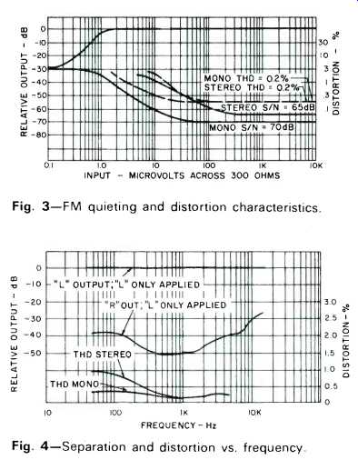
Fig. 3--FM quieting and distortion characteristics.
Fig. 4--Separation and distortion vs. frequency.
Amplifier Measurements
Harmonic and Intermodulation distortion characteristics of the amplifier section of the TR-1055 are shown in Fig. 5, the former with an input signal of 1 kHz applied to the Tape 1 inputs. Under these test conditions, with both channels driven and connected to 8-ohm loads, power output reached 66 watts for the rated THD of 0.2%. Tandberg makes no claims with respect to this measurement, preferring to quote power output over the entire frequency range from 20 Hz to 20 kHz at 55 watts.
Figure 6 is a plot of power bandwidth which extends from 4 Hz to 60 kHz (as opposed to the 40 kHz limit claimed by the manufacturer). Note that at 10 Hz, the curve crosses the 0 dB level, corresponding to 55 watts. At the high end of the audio range, the amplifier actually produces a bit more than 55 watts. At the rated power output, THD at 20 kHz measured 0.08%, as shown in the continuous frequency vs. THD graph of Fig. 7. While we normally present frequency vs. THD curves for three different power levels (full power, half power and 1 watt levels), there was no point in showing the lower output curves in the case of this receiver, since even at full power output, THD was below 0.2% for all measured frequencies.
At the one watt level, the curve would have actually crossed the "full power" curve because of residual hum. Residual hum measured via the Tape input terminals was-76 dB with reference to full output. Phono hum measured -66 dB with reference to a 2 mV input signal and with the input sensitivity adjusted for maximum sensitivity. Since most magnetic cartridges will produce more than 2 mV nominal output with typical record groove velocities of 3.14 cm/sec., this hum figure is quite impressive and must be interpreted in the light of actual cartridge outputs rather than with respect to the high sensitivity circuits of the phono preamplifier of the TR-1055.
Overall frequency response was flat within 1.5 dB from 4 Hz to 70 kHz. At 100 kHz, audio response was down 2 dB. Phono overload occurred at anywhere from 35 mV to 100 mV, depending upon the setting of the input sensitivity control.
Tone control, loudness, and filter response characteristics of the Tandberg receiver are plotted in Fig. 8, and if you want to see how filters should be designed for greatest effectiveness, take a look at the steeper sloped hi-filter and the low-cut filter curves. Note that at 80 Hz and 8 kHz the filters have just barely begun to cut into the response, while at 30 Hz (a prominent "rumble" frequency) and at about 17 kHz, attenuation produced by these two filters is some 15 dB. The alternate hi-filter has a more gradual slope and is intended for use when moderate high frequency attenuation is desired. Alternatively, both high filters may be used in tandem, which results in a somewhat steeper attenuation of highs with a lower crossover frequency.
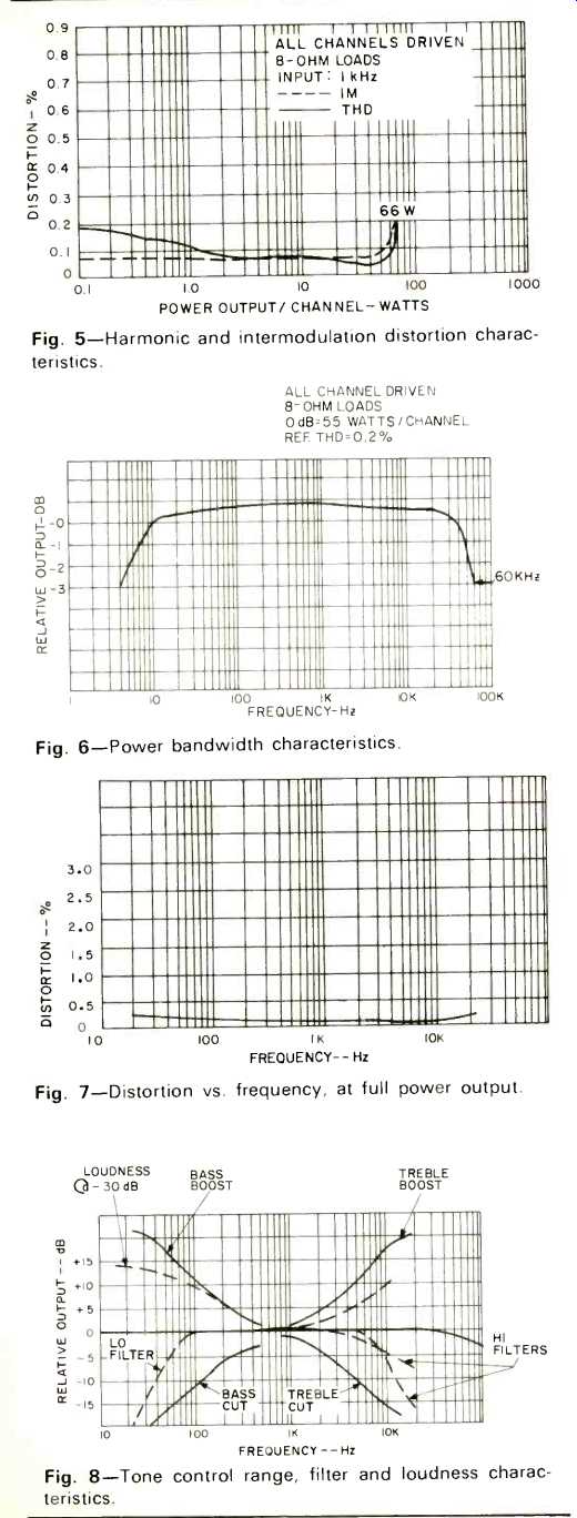
Fig. 5--Harmonic and intermodulation distortion characteristics.
Fig. 6--Power bandwidth characteristics.
Fig. 7--Distortion vs. frequency, at full power output.
Fig. 8--Tone control range, filter and loudness characteristics.
Listening Tests
Before describing our reactions to the Tandberg TR-1055 under actual listening conditions, there is a useful, additional "surprise" on the front panel which we found. When you pull out on the speaker selector knob, the signal strength meter becomes a power output indicating meter. Since it is calibrated in arbitrary numerals from 0 to 20, Tandberg thoughtfully supplies a chart in the owner's manual which relates meter readings in this mode to actual power output, depending upon speaker impedance. A very handy addition for such a powerful set if you have any doubts about the power handling capacity of your associated speaker systems.
We were not surprised to find that FM performance, and particularly stereo FM, was superb. The very excellent capture ratio of this unit actually resulted in audibly better stereo FM--particularly from those stations where we ordinarily detect small amounts of multipath distortion even with "best" antenna orientation. Not a single "usable" signal was blocked by the introduction of the muting circuit, thanks to its very low but effective threshold setting of 3µV.
As for the amplifier section, the availability of full power even down to 20 Hz made an audible difference as we tried to drive our low efficiency speaker systems to louder and louder listening levels. We must confess that they "gave up" before the amplifier section of the TR-1055 did--especially on low, low bass passages of music. This was confirmed by continued monitoring of the amplifier's output waveform while listening to different program material. There's enough reserve power here to really take advantage of dual location of pairs of speaker systems--even low efficiency types. We did find that the treble emphasis afforded by the loudness control was a bit much for us, and so if you use the loudness control at low listening levels you may want to turn your treble control down to about " 10 o'clock" to offset this slightly exaggerated treble emphasis. Chances are, though, that when you are working with this powerful unit, you're not going to spend much time listening to "background music"--it's just too fine an instrument for "casual" listening.
-Leonard Feldman
(Adapted from: Audio magazine, Jul. 1974)
Also see:
Tandberg Model TR-2075 Stereo AM/FM Receiver (Equip. Profile, Mar. 1976)
Tandberg TR 1020 Receiver (Feb. 1973)
Tandberg 3080A FM Receiver (Equip. Profile, July 1989)
Tandberg Compact Disc Player (Nov. 1987)
Tandberg TCA 3018A Preamp and TPA 3026A Amp (Apr. 1987)
Tandberg 3008A Preamp and 3009A Amp (Jan. 1986)
= = = =