David Lane Josephson
With this installment, Mr. Josephson concludes his article on microphones, the first two portions of which appeared in December, 1973, and July, 1974.
Brass, Woodwinds, and Percussion
Small brass instruments, such as trumpets, saxophones, etc., can be miked effectively by the use of one decent quality capacitor or dynamic unit located roughly four feet out from the bell of the instrument. It should be remembered that the recording mic pickup, where the aim is for the highest accuracy of the live sound, is different from the public address type of mic placement where the aim is for reinforcement of the sound level. Brass instruments can produce very intense spikes and transients of sound which will distort and overload the mic if placed too close.
Woodwind pickups may be made in basically the same manner as brass pickups. The woodwinds are generally a part of a group, which will be covered later. Individually they may be miked with good quality dynamic or velocity units, placed roughly four feet from the instrument. At this distance proximity effect isn't troublesome and unidirectional mics may be used.
Percussion instruments, such as drums, must be miked with great care. Sharp, spiky instruments, such as snares and cymbals, should always be miked with capacitor units, such as the Neumann KM-83. Bass drums may be miked with just about anything at all, and many recordists use general purpose cardioid dynamics for this purpose, located just inside the drum itself, if it is open from the rear, or right in front if it is closed. A general stereo drum pickup may best be made with two high quality omnidirectional dynamic or capacitor mics, such as the Shure SM-76 or Neumann KM-83, directly over the drum set. These can be mixed for mono or one mic may be used.
Bands Rather than individual instrument pickups, discussed above, the amateur recordist's most common pickup will probably be small musical groups of one kind or another. These may be miked with the multi-track technique, using individual instrument pickups mixed into two or four channels (during recording or later on by playback of a multi-channel tape), or else a general pickup using two mics with an accent if needed may be used. Either will give a pleasing stereo effect.
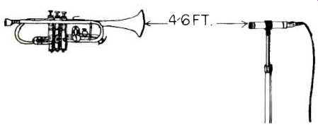
Fig. 4--Single mic pickup of brass instrument. Omnidirectional or unidirectional
capacitor or dynamic preferred; mic must be able to accurately reproduce
spikes of sound from these instruments. For this reason, capacitor mics are
preferred.
Generally, the multi-track technique is preferred by commercial recording studios simply because it allows the musicians to come into the control room and decide for themselves where they want the various instruments placed in the stereo illusion.
Each individual microphone is assigned to one channel on a multi-track tape (anywhere from 4 to 32 channels or more), the playback signal from which is then mixed down into quadraphonic or stereo.
For very simple but pleasing monaural recording, one single spot in the recording hall or studio may usually be found where the direct signal from the band will balance with the reflected sounds from the ceiling, floor, and walls. Several old and well respected record companies used this method exclusively, and it produced some of the clearest recordings ever made. The theory behind this simple approach is that if more than one microphone is used per channel, the same.
signal of audio will arrive at all of the microphones used to feed a given channel at different times, thus producing phase differences when all the microphones are mixed together that make the tape sound tinny and rather weird. If the distance from one microphone to another microphone used to feed the same channel (at the time of recording or later, in a multitrack mix) is more than six or eight times the distance between the microphones and their respective sound sources, however, the incident sound striking the wrong microphones will be low enough in level so this audio multipath distortion won't happen. With the two mics used for a stereo pickup, though, this isn't a problem since the mics are used to feed separate channels.
There are generally two schools of thought regarding the general binaural stereo pickup, using two microphones, with accents if needed. One method is to form an equilateral triangle, each side as long as the width of the band being recorded, and the apex somewhere out in the audience. Two mics are used, located exactly midway between floor and ceiling (if the ceiling were 20 feet high, each mic would be 10 feet off the floor) and about ten feet from the apex of the triangle and pointed toward the front. The main problem with this type of pickup is that if the hall is too reverberant or the audience too noisy, the reflections and audience noise may be louder than the band being miked. Mics should be high quality unidirectional capacitors or dynamics, with capacitors used if at all possible. This brings us to the other general pickup mic technique. Two mics are used, omnidirectional capacitor or dynamic (good quality dynamics being almost as good as capacitor mics if they are omnidirectional) units, mounted at most two inches off the floor at the very edge of the stage.
The diagram shows how they should be placed. This technique can result in a surprisingly accurate stereo pickup that is acoustically pleasing as well. Shure and Electro-Voice both make stands for this purpose; the Shure being a wire tripod in sizes for ¾- and 1-in. diameter mics, the Electro-Voice being a hunk of foam with a cutout for a mic. In any case, the point is to get the microphone as close to the floor as possible without actually touching it, to eliminate any possible reflections. The basis for all this trouble is that the prime reason most amateur band recordings are tinny and lack depth is the sound reflections from the floor, walls and ceiling that cause the audio multipath distortion mentioned above. This is caused by the same sound arriving at one mic at different times. First there is the direct sound from the instrument, followed by bounce signals from the walls, floor and ceiling.
If the distance is great enough, this is heard as reverberation, but if the difference between the direct path and the bounce path is relatively small, then the bounce signal is heard as multipath. The zero-reflection principle may also be used with the mics on the walls or the ceiling, whichever is closer to the instruments being miked and whichever is the most reflective.
For any live pickup, it helps immensely to experiment during a rehearsal with placement of mics. The walls and floor, for example, may be so heavily deadened already that the extra floor noise picked up with the zero-reflectance technique would cancel out any clarity that might be gained. On the other hand, it may be found that the room is so reflective than an elaborate multi-track pickup would result only in a hodgepodge of mushy sound. A considerable amount of liveness may be tolerated in a rehearsal that need not be expected in the actual performance-the audience makes a perfect sound absorber.
If it is found that one particular section of the band is weak when the microphones are placed best for the overall pickup, that section may be reinforced with an accent mic. This can be any half-decent unidirectional unit, since its prime purpose is reinforcement in volume level of a section of the band already audible through the main mics.
Performance Techniques
Small classical music ensembles, such as string quartets or chamber music groups, should be miked with a plain general pickup. The mics used are usually velocity or omnidirectional capacitor units. The mics are usually arranged around the instruments, in their usual performance setup, rather than the other way around. Each individual instrument may be miked separately and mixed later if necessary. With a decent ensemble (where mistakes in volume balance are not a problem), this shouldn't be required.
Orchestra pickups may be made with either single-mic techniques or multi-tracking. The same equilateral triangle scheme used for bands should be used, at least as a start in experiments. The zero-reflectance technique with the mics at the front of the stage generally won't work, since the instruments to the rear are much too far away from the mics.
A zero-reflectance pickup with the mics on the ceiling might work-this writer hasn't seen any examples of this technique being used for orchestra pickups. The mics should be "flown" from the ceiling by nylon fish line or by their own cables.
Hangers, such as the Neumann Z-68, will eliminate the strain placed on the mic connector itself (which might end with the mic dropping on the audience). High quality unidirectional capacitor mics, such as the Neumann KM-84, should be used.
As with band recordings, an accent mic may have to be added to reinforce a weak section of the pickup. This is often the string section, where the subtle harmonics are easily lost as the distance between mic and instrument increases.
Drama pickups present an entirely different problem. A common technique is to place four or six mics, usually unidirectional dynamics, in the footlights of the stage. The left two or three are mixed into the left recording channel, and the right group go to the right channel. Often only two mics will be sufficient. If the mics are not too heavily coupled to the floor by way of their stands, foot stomping and other noises are effectively eliminated. The Shure and Electro-Voice floor wave stands are excellent for this purpose. It is also possible to mount a pair of mics in the proscenium arch, using a pair of decent unidirectional capacitor or dynamic units.
When the actors can project and be heard effectively in the audience, there should be no trouble in securing a decent pickup from the stage. Microphones may be hidden on the set or on the performers for reinforcement. If there is a particularly intimate scene in the play, it may be worthwhile to plant a mic in the set near where this is to take place, and fade this accent mic in when needed for reinforcement or special effects.
Usually, if a working rapport is built between the recordist and the company producing the play, there is a far better chance of the recording coming out as everyone had wanted.
This way the recordist can begin from a point of knowing what the desired mood and impressions are ... and can place mics and ride level accordingly.
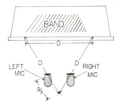
Fig. 5--Stereo pickup using equilateral-triangle placement. Two mics shown
may be replaced with a pair of mics, as shown in Fig. 7, for a Blumlein-type
or "X-Y" pickup, or with one mic at the apex of the triangle for
mono. Distance "D" is the same for all sides of the triangle, and
the distance between the mics and the apex is one-third of that or D/ 3.
Mics can face either straight forward or can face the two angles on the stage.
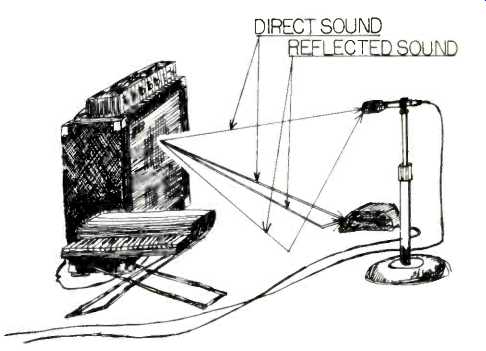
Fig. 6--Illustration of the zero-difference of floor-wave mic technique.
Note that the difference between the direct sound distance and the reflected
sound distance is greater with the mic mounted on a stand. Double lines indicate
sound paths to the floor mic in a block of foam.
A very puzzling thing to be on the lookout for in drama pickups are singing filaments. The light dimmers used for many low-budget theaters have very poor output filtering for the SCR hash (noise made when the silicon-controlled rectifiers switch on and off), which doesn't do the dimmer or the lights any harm, but causes a 1,000 Hz or so tone to be emitted from all the lamps on dimmers-especially when dimmed to very low levels. This may be picked up from as far away as 20 feet, and it is nearly impossible to filter out. The recordist should make absolutely certain that the theater in which he is to record has quiet dimmers-or else don't go near the ceiling with the mics. A piece of # 14 insulated wire about 30 feet long, scramble-wound on a wood or plastic core and placed in series with each dimmer output, should solve the problem.
Most amateur recordists attempt at one time or another to produce live actuality tapes--bird sounds, sporting events, sound effects. These require only a fertile imagination and halfway decent equipment to produce. Almost all of the commercially available sound effects records were produced in a studio, using equipment made especially for sound effects. But for the amateur with limited resources, improvisation is the only way.
Surprisingly good bird and wildlife sounds may be recorded with a wooden salad bowl used as a parabolic reflector and an omnidirectional dynamic mic, hooked up to a decently quiet portable tape recorder like a Sony 800 or a Nagra. The mic is suspended in the focus of the parabola, and moved closer in for sounds further away and vice versa.
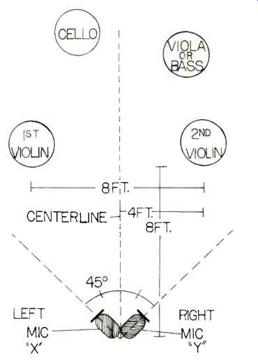
Fig. 7--Stereo pickup of a string quartet, using the "X Y" or
semi-binaural technique. This placement also results in a good ambience level
for Dynaco or SQ quadraphonic encoding. Ideally, the mics should be at the
same vertical point, the only difference being their horizontal angle from
the center line. This can be done by mounting the two mics one above the
other on a stand, or by mounting the right mic on the left and vice versa,
but with the left mic pointing left and the right pointing right. An ideal
single mic for this pickup is the Neumann SM-69fet, which includes both mics
needed in a single case.
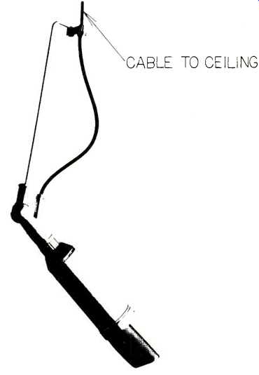
Fig. 8--Neumann Z-68 auditorium mic hanger. With this fixture or a homemade
one like it, the mic may be hung from the ceiling without having the entire
weight of the mic on the mic connector. The cable itself is more than strong
enough to support any mic, but the connectors can often come loose under
strain. A hanger like this also permits the mic to be angled for best pickup.
Extra Hardware
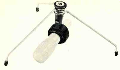
Fig. 9--A typical zero-reflectance mic stand, the Shure S-55P. The mic should
be adjusted so that its grille is about /e-in. from the floor.
Microphone stands are probably the most taken-for granted single item in the whole bunch of equipment used for recording. Many recordists have never thought of making their own mic support equipment, but it's entirely possible. Desk stands are the easiest to make. A female 5/8-27 flange and a length of threaded pipe are available for far less than a good desk stand and may be mounted on a piece of wood-it doesn't have to look like all the other desk stands in the world. Floor stands are usually best bought unless you're a fairly competent wood and metal worker--the Atlas MS-25 and CS-52 being among this writer's favorites. The cheap imported units sold under various house names universally tend to be too light, and sheer weight (or extension of legs) is often what makes a stand tip-proof in any particular situation. The combination of a general purpose stand, such as the Atlas MS-25, with a small boom attachment, total cost roughly $35.00, can handle almost any basic miking placement. The stand itself (floor stands tend to be curiously universal in this respect) will rise a little over five feet, and the boom will add an extra two feet of useful reach from that. The boom itself is close to three feet long, but this full length cannot be utilized with any but the lightest mics. An integral stand/boom unit, such as the Atlas BS-36 or the Neumann M/G-35, are larger and considerably more stable units of the same basic stand-plus-boom genre.
There are a number of ways to support a microphone besides hand-holding or mounting on a stand which rests on the floor. Many low-budget noncommercial radio stations "fly" their microphones, even huge velocity mics like the RCA 44-BX, from ropes or nylon lines strung from the ceiling. This is often a utilitarian approach when boom stands are out of financial reach for the recordist. An array of sturdy hooks and lengths of nylon rope is probably just as useful as a bunch of boom stands--and much cheaper. A very useful kit of gear to have around for the floor stand user is a variety of mic fittings and adapters. Unfortunately for the recordist, the 5/8-27 thread that has been adopted as standard for mic stands in this country is a custom thread, and this recordist has not been able to locate taps or dies for this thread anywhere. RCA has the right idea by making most of their professional mics mount on 1/2-in. pipe stands-this can be adapted from any mic stand, and is easily available anywhere for custom stand making. For the recordist with factory-made stands, however, a collection of threaded pipes, female-to-female couplers, lengths of running thread, flanges, swivels, etc., which are available from almost all electronics parts dealers, will be very useful.
The zero-reflectance (floor wave) miking technique has spurred its own separate collection of mounting hardware. Shure makes two models of stands (which look like ordinary tripod-type desk stands except the mic is under the legs instead of on top), one for 1/4-in. diameter mics and one for 1-in. Electro-Voice has a block of urethane windscreen foam, known as a mike mouse, that can be stretched to fit any stick-type microphone, and which has the added advantage of protecting the mic should it be kicked or fall off the stage.
Phasing
Most primers on microphone technique insist that all mics must be phased identically. This means that if all the mics used for a given pickup are given a positive pulse of audio, a positive pulse of electricity will appear at the "hot" lead of each mic output. If a mic is out of phase, its output will be a negative pulse. The phase may be reversed by transposing the two signal leads on a low impedance mic or reversing the two mic element leads inside a high impedance mic. In general, common phasing is a good idea, but reversing the phase of one mic in a pickup may save that particular mic placement.
Boominess and excessive reverberation in a room may often be eliminated by placing an additional mic at least six times as far away from the main mic(s) as they are from the sound source(s). This echo-suppression mic is then mixed 180-degree out of phase with the others. The sound arriving at the echo suppression mic from the sound source itself will be insignificant, but the sound arriving as a bounce signal will arrive at just about the same time and at the same level as at the main mic(s). Thus the output phase will be roughly the same-when they are mixed out of phase, anything arriving at one mic will automatically be cancelled out from the other mic-in this case, the echoes, reverberation and some of the background noise will be cancelled out. Experiment with the placement of the echo-suppression mic for best results.
Another bunch of accessories the amateur recordist would do well to have are various materials for suppressing noise: blocks and sheets of open-cell urethane foam, shock mounts, and some filters and attenuators. Most commercial windscreens consist of plain open-cell urethane foam, the same as is used in the newer automobile air filters. The differences between open-cell and closed-cell foam is that the walls of the air bubbles in the foam have disappeared in open-cell foam and are still solid in closed cell foam. As a result the open-cell foam can pass air while reducing its velocity, while the closed-cell foam cannot and is good for insulation and mattresses. The open-cell foam may be purchased in sheets 2-in. thick and wrapped around a mic to eliminate wind and breath noises at far less than the cost of a commercially made molded-foam windscreen. One thing that is extremely important when using windscreens with directional mics is to be sure that all open ports and vents in the case are windscreened just as well as the front grille. These ports are often more sensitive to wind and breath noise than the front of the mic, which is often windscreened inside already. The vents and ports may be found by looking for open holes, slots, and extra grilles anywhere on the mic case.
A shock mount is a device designed to isolate the mic from picking up any noise from its support. These are usually tubes of metal which hold the mic rigidly, suspended from a ring of metal by rubber bands. The ring is then mounted to the stand.
Other designs use sheets or rings of rubber between the two rings or tubes. This is another item that may be made by the mechanically talented recordist. A number of microphone companies have recently come out with filters, attenuators, and phase reversers that fit in the line from a microphone to the mixer or recorder. The Shure line includes attenuators (which reduce the audio level from very high output mics to avoid distortion), high-pass filters (to eliminate bass accentuation), and phase reversers (two jacks with the two signal wires reversed in going through). Electro-Voice's line consists of variable filters and fixed attenuators.
A decent mixer is almost a necessity for anything but the strictest single-mic mono recording. Having a unit with low impedance balanced inputs, reliable level meter and extras like a level-set oscillator, low-cut filters, and quiet potentiometers, can be a real pleasure. The Shure M-67 and M-68FC are good versatile units as is the Sony MX-16 series. Several other manufacturers put out mixers that can serve the amateur well. The circuits for any of this basic audio mixing and switching gear are very simple, and they may easily be built from scratch.
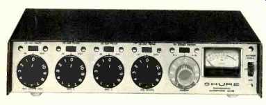
Fig. 10--An ideal small mixer for recording, the Shure M-67. This unit
has four inputs; all may be used for low impedance balanced mic inputs; #1
may be switched to built-in tone oscillator for level correction, #4 may
be switched to 600-ohm balanced line input. All inputs may have low-cut filter
switched in (about 10 dB down at 100 Hz) for rumble suppression or voice
tailoring. The unit has mixing buss jack so that more than one mixer can
be paralleled for more inputs; all have the same output; meter on each reads
only levels going out of that particular submixer. Outputs at both mic level
and 600-ohm balanced line level (up to about +12 VU).
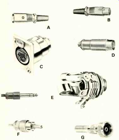
Fig. 11--Microphone connectors. Balanced types include Cannon male cord
plug, A; Cannon female cord plug, B; Cannon female chassis jack, C, and DIN
type, D, which has female counterpart. Unbalanced connectors include phone
plug and jack, E; phono plug, F, and Amphenol screw type, G.
Microphone Cables
Getting the signal from the microphone to the mixer or recorder is almost as important as getting the mic in the right place to begin with. Most cables consist of two plastic- or rubber-covered conductors twisted together, shielded with braided strands of fine bare wire, and the whole encased in a plastic or rubber jacket. High impedance mics are universally unbalanced, and only one conductor plus shield is used. Foil shielded cable should never be used for mic lines, or anything else that must move from time to time. The foil cracks and shrivels up very easily, destroying the shield. Most foil cables have a single "drain wire" running along with the foil shield, but if the foil disintegrates, the drain wire isn't much of a shield.
Most professional microphone lines are connected to one another and to the mic and recorder by round three-pin connectors 34-in. in diameter known as "Cannon XLR connectors." There are two fiercely warring schools of thought on this subject, the resilient (original Cannon) proponents and the rigid (old Cannon and new Switchcraft) people. As shown in the photo, the pins of the connector are set in a plastic insert inside the metal shell. The new series of Cannon connectors, as made by Cannon, have the pins set in a block of rubber. In the first Cannon connectors and in the present Switchcraft and Amphenol connectors, the pins are set in rigid plastic or bakelite. The resilient rubber connectors are supposed to make contact better since they can move around, but the new Switchcraft connectors have captive shell screws (means they can't get lost) and a ground lug that connects to the shell. This writer hasn't noticed any difference in reliability or noise between the rigid and resilient, although the rigid types may melt during soldering, and sometimes crack, while the rubber ones don't. The other type of microphone connectors in use today are mainly for high-impedance mics. The 'phone plug and its miniature counterparts are simply rods of metal with isolated tips. The ground wire is connected to the shell, and the signal wire goes to the tip. There is no way these 'phone plugs can be locked to the equipment as can Cannon connectors, and they will pull out if tripped over. The original high impedance mic connector, and one that is still in use, is the Amphenol MC-1 series, and its equivalents. This uses a 5/8-27 threaded ring which screws the male and female sections together, the center of the two being the signal lead.
These, being unbalanced only, are for high impedance mics only. Amphenol also makes several types of multi-conductor connectors secured with screw rings which are used widely on the mic end of cables and in communications gear but not much for audio recording. One final word to the wise about connectors--avoid plastic like the plague. Plastic-shelled phone plugs and Cannon-type connectors will always break if stepped on or bashed against the floor (which too often happens), and the molded plastic connector-plus-cable assemblies are constantly falling apart. What's worse is that there is no way to remove the plastic potting compound and solder the pieces together again. Take a few extra minutes and make up your own cables with good metal connectors and decent shielded cable--it'll save you many hours of grief at the recording site.
(Audio magazine, Aug. 1974)
Also see:
Microphones Vital Link in the Recording Chain--Part 2 (Jul. 1974)
Microphones--The Vital Link in the Recording Chain--Part 1 (Dec. 1973)
A Microphone Primer: Basic Construction, Performance, and Applications (Dec. 1972)
A Microphone Primer: Conclusion (Feb. 1973)
Mike Technique and Sound Effects (Dec. 1974)
Recording in 2 and 4 Channels (Dec. 1973)
Electro-Voice microphones (Jan. 1973)
= = = =