by DON DAVIS
Air Absorption
Higher frequencies, those between 1000 and 10,000 Hz, attenuate progressively more rapidly than do the lower frequencies. This frequency-discriminative characteristic is caused by air absorption and humidity. As frequency increases and humidity decreases, the attenuation increases beyond that predicted by the formulas already given.
Figure 8 allows the calculation of the expected additional attenuation when the frequency and relative humidity are known. Typically at distances of 50 to 70 feet this additional absorption causes the desired acoustic response to exhibit a gradually sloping response starting about 2500 Hz and being about 5.0 to 6.0 dB lower at 10,000 Hz than at 1000 Hz. Air absorption plus the typical random incidence response of 1/2-inch condenser measuring microphone results in a house curve at 70 to 100 feet that looks like Fig. 9.
Equivalent Acoustic Distance (EAD)
Equivalent acoustic distance (EAD) is the maximum distance from a performer that still allows a clear intelligible understanding of his message without the use of a sound system. Obviously this distance will vary with the:
1. Acoustic output of the performer.
2. Hearing acuity of the listener.
3. Ambient noise level.
4. Ratio of direct-to-reverberant sound.
Very useful charts have been compiled in recent years for showing the expected effects of performer-listener separation in given ambient noise levels. In considering typical noise levels in even the quietest environments versus a normal talker's acoustic output, twenty feet of performer listener separation would appear to be a practical maximum for an EAD. See Fig. 10.
The Effect of Multiple Microphones
The number of open microphones ( NOM) directly affects the acoustic gain of a sound reinforcement system. Every time the number of open microphones is doubled, the potential acoustic gain (PAG) drops 3 dB. 10 logo NOM=loss in gain
This assumes, of course, that the microphones are in the reverberant sound field of the loudspeaker.
Calculating the Needed Acoustic Gain
There is an almost universal tendency today to under-design the typical sound reinforcement system in spite of the fact that it is possible to calculate quite accurately the actual needed acoustic gain ( NAG) . Knowing the actual acoustic gain .required can ensure against excessive measures being undertaken merely as a technical tour de force.

where AD, =the distance in feet from the talker to the farthest listener used as r in the formula 10logoL\4f) + (R)Jte' AEAD = the equivalent acoustic distance in feet used as r in the same formula NOM = the number of open microphones used as NOM in the formula: 10 logo NOM.
+6 dB =working "headroom" below unity gain.
See Figs. 11 and 12 for definitions of D2, D.., and D,.
For an example, in a room where S= 100,000 f9, a=0.12 and the loudspeaker array had a Q=5, we could calculate the following deltas for Do = 125': eDo =-34.96 EAD = 8': oEAD =-21.86 NOM = 2: oNOM = +3.01 Converting oDo and EAD to opposite signs for use in the NAG formula, we find 34.96-21.86+3.01+6 dB=22.11 dB.
NOTE. The used throughout this paper denotes the dB equivalent of the parameter, rather than its usual application as a change or difference. En.
Calculating the Potential Acoustic Gain
The potential acoustic gain (PAG) is that maximum amplification possible at unity gain expressed as a relative advantage at the farthest listener's ears. For example, the actual unity gain would remain the same for any given microphone loudspeaker separation but the apparent acoustic gain at the farthest listener will increase if the loudspeaker is placed closer to the listener than the talker is.
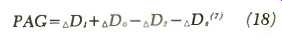
eq (18)
where oD1 = the distance in feet from the microphone to the loudspeaker is converted by means of:
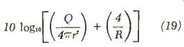
eq (19)
D1 should be made equal to or greater than D, whenever possible in order to ensure that the microphone is in the loudspeaker's relatively stable reverberant field, hence at a distance allowing maximum acoustical separation. D, should not, however, exceed 45 feet or time-delay problems will be encountered. 1:1>D,< 45'. where AD,=the distance in feet from the loudspeaker to the farthest listener converted by means of formula 19.
D: should not exceed 4D, if the ratio of direct-to-reverberant sound at the farthest listener's ears is not to exceed-12 dB. Solutions to situations where D, exceeds 4D, are:
1. Shorten D,. For example, use overhead distributed systems in place of a single-source array, thereby substantially shortening the D, to any given listener at the expense of realistic directional localization.
2. Increase the Q of the loudspeaker array.
3. Increase the a of the space.
4. Increase the physical size, thus surface area, of the space. (At the drawing board stage this can often be considered seriously.) In any case, D2 4D, is the rule.
D,=the distance in feet from the talker to the microphone converted by means of the above formula.
Shortening D. is the easiest way to increase PAG substantially.
----------
[* Knudsen and Harris, Acoustical Designing in Architecture, Wiley, New York, 1950. ]
[ Don Davis, New ways to look at needed and potential acoustic gain, Altec Lansing Technical Letter No. 198, 1969. ]
[ H. F. Hopkins and N. R. Stryker, A proposed loudness-efficiency rating for loudspeakers and the determination of system power requirements for enclosures. Proc. IRE, March, 1948.C. P. Boner and R. E. Boner, The Gain of a Sound System, JAES, Vol. 17, No. 2, April, 1969. ]
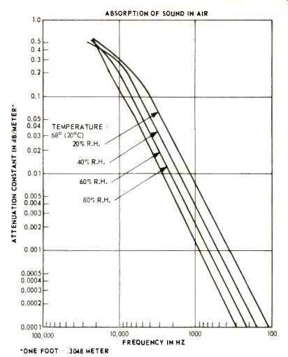
Fig. 8-The effect of humidity and frequency on air absorption of sound.
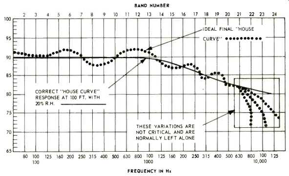
Fig. 9-A typical "house curve" considering air absorption and microphone characteristics.
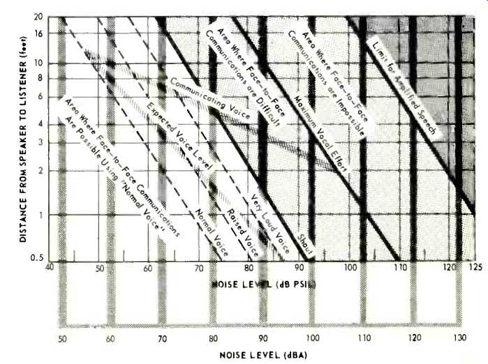
Fig. 10-Establishing an EAD by considering the ambient noise level.
---------
Despite overwhelming popular belief in the ability of cardioid microphones to increase acoustic gain, it is normally easiest to reach maximum acoustic gain using a high-quality omnidirectional microphone. In a properly designed sound reinforcement system every effort has been made to maximize acoustic gain by providing the greatest possible acoustic attenuation between the loudspeaker array and the microphone. This is done by placing the microphone in the far reverberant sound field of the loudspeaker array. Hence, the sound arriving at the microphone impinges randomly on it and its directivity is not of any use.
The proper use of directional microphones is to discriminate against nearby unwanted noise sources that are at a distance substantially less than D, for the space. For example, in our theoretical building we calculated a needed acoustic gain (NAG) of 22.11 d$. By applying the above rules we can now find:
1. D,=40 ft. (D,=34.29 and D,?D,< 45'; therefore, 40' makes a completely logical choice for DI.)
2. D,=119 ft. 4D,=137.17' and D,< 4D,.
[...]
=============
(Audio magazine, Oct. 1970)
Also see:
Computer-Aided Audio Calculations (Nov. 1983)