

MANUFACTURER'S SPECIFICATIONS:
FM Tuner Section
Mono Sensitivity: 12.0 dBf (2.2 NV).
50-dB Quieting: Mono, 18.3 dBf (4.5 NV); Stereo, 38.3 dBf (45 pV).
S/N: Mono, 75-dB; Stereo, 68 dB.
Muting Threshold: 20 dBf (5.4 pV).
Frequency Response: 30 Hz to 15 kHz, +0.5,-1.5 dB.
THD: Mono, 0.1 percent at 1 kHz; Stereo, 0.15 percent at 1 kHz.
Capture Ratio: 1.5 dB.
Selectivity: 70 dB.
Spurious Rejection: 90 dB.
Image Rejection and I.F. Rejection: 85 dB.
AM Suppression: 55 dB. SCA Rejection: 70 dB.
Stereo Separation: 45 dB at 1 kHz, 30 dB at 10 kHz.
Amplifier Section
Power Output: 104 watts per channel, 8 ohms, 5 Hz to 20 kHz, with no more than 0.1 percent THD (150 watts per channel, 4 ohms).
Damping Factor: 100 (1 kHz, 8 ohms).
IMD: Less than 0.004 percent at rated output.
Frequency Response: Phono, RIAA ±0.3 dB; High Level, 10 Hz to 30 kHz +0, -1.0 dB.
Input Sensitivity: Phono, 2.0 mV; High Level, 100 mV.
Phono Overload: 120 mV.
S/N: Phono, 83 dB "A" Weighted; High Level, 94 dB; Main Amp, 115 dB.
Bass and Treble Control Range: ±12 dB at 20 Hz and 20 kHz.
Output Levels: Rec Out, 100-300 mV variable; Preamp Out, 1.0 volts; Headphone Out, 60 mW/8 ohms.
Contour Control (Maximum): -12 dB at 20 Hz, -23 dB at 3 kHz, -14 dB at 20 kHz.
General Specifications
Power Requirements: 100-120V/220 - 240V, 50/60 Hz, 400 watts (max.).
Dimensions: 19 1/8 in. (50 cm) W x 3 1/2 in. (8.9 cm) H x 14 1/2 in. (36.8 cm) D.
Weight: 38 lbs. (17.27 kg).
Price: $1200.00; optional remote control system, $190.00.
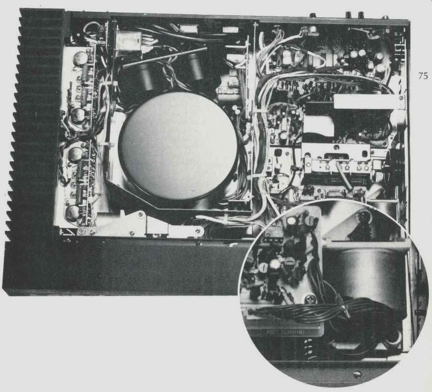
Fig. 1--Close-up view of the AM/FM variable capacitor.
There is so much that is new and different about this, Nakamichi's first integrated receiver, that it would take several more pages of this magazine to fully describe it than have been allotted to this test report. We will therefore simply attempt to discuss some of the highlights of this FM-only receiver. The low-silhouette black, knobless front panel is very reminiscent of the styling treatment used by Bang and Olufsen in their award winning industrial designs for receivers, but with a Nakamichi touch or two added. All major control functions are handled by touch-sensing switches.
A long, narrow slot along the entire width of the upper section of the panel houses a linear FM dial scale and pointer at the right, for about two thirds of its length, while the remainder of the slot is taken up by a striped, illuminated green filter and film shutter that regulates how many of the green stripes can be seen from the front of the receiver. This serves as an indication of volume level (calibrated from 0 to 10), which is controlled by touch-sensor switches that actuate a motor to drive the actual volume-control potentiometer.
Additional touch-sensor switches along the central section of the front panel include an audio mute switch, five program selector switches, three tape monitor switches (off, plus two tape decks), a stereo/mono switch, Dolby FM switch, hi-blend switch, FM muting switch, four pre-set FM station switches lettered A through D, and up- and down-scan tuning switches. Along the very bottom of the panel are five small illuminated sliders. These control bass and treble response, channel balance, volume-contour pre-set, and FM muting threshold. Two stereo phone jacks are also positioned along the bottom edge of the panel.
The rear panel of the Nakamichi 730 is a bit more conventional in its layout. A 75-ohm coaxial connector is at the upper left and next to it are 300-ohm antenna terminals, while just below is a 20-dB attenuator switch and a chassis ground terminal. Phono, AUX and two sets of tape inputs and output jacks are also located in this area of the rear panel, and the recorder output jack level is controllable by means of a miniature control and knob just above these jacks. What a splendid idea for matching record output levels to the needs of one's particular tape deck, thereby enabling the user to operate the tape decks record level controls at most convenient points of rotation! Preamp-out/main amp-in jacks, shipped with interconnecting jumpers, come next, followed by two convenience a.c. receptacles and a master power on/off switch which is normally left in the "on" position so that the optionally available remote control unit can turn the unit on and off and so that the front panel "touch sensor" power switch circuitry can also turn on the rest of the unit. Spring-loaded, color-coded speaker terminals (only enough for one pair of speakers) are located at the extreme right of the rear panel.
Circuit Features and Highlights
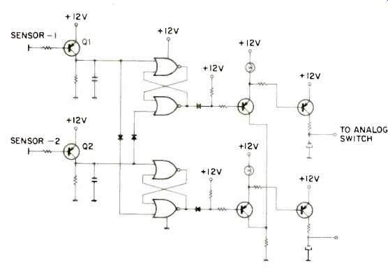
Fig. 2--Function selector network.
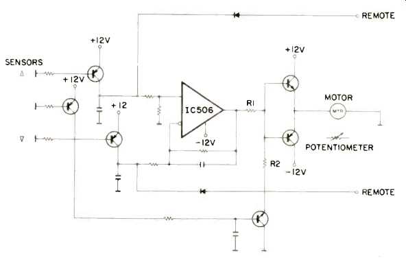
Fig. 3--Volume control network.
A close examination of the detail view of Fig. 1 discloses that the tuning system of the Nakamichi 730 employs a conventional tuning capacitor. How, then, can it scan up and down the dial, remember four pre-set stations, and lock in when stations are properly tuned? (Most receivers and tuners with this capability employ varactor tuning diodes.) By having the tuning capacitor driven by a tiny motor, that's how! The 730 employs a most unique tuning system. A touch of one of the scanning sensors starts the tuner scanning for stations. The command is committed to IC memory. The tuning motor turns, and the rotation is transmitted through gears and a timing belt to the variable capacitor. If the level of a signal scanned is above threshold, the tuner next checks noise level for an indication of quieting and seeks out the center of the channel as indicated by the zero-point of the detector's "S"-curve. The motor stops rotating, and green tuning indicators on either side of the dial pointer glow. Seven seconds later the system "locks on" to the signal. This system offers tuning precision within ±5 kHz of channel center.
The variable capacitor includes an AM section, even though there is no provision for AM reception in this receiver. The AM variable capacitor is actually used in connection with the four-station pre-set feature, its capacitance serving as part of a discharge circuit, with capacitance varying in accordance with the angle of rotation of this capacitor, which is mounted concentrically with the main FM tuning capacitor sections.
Mode and function selection are controlled using logic-controlled, touch-sensor switches, as previously explained.
Figure 2 shows the basic circuit for function selection. Touching sensor 1 causes a resistance change which turns on Q1.
This command is committed to a C-MOS memory, and an electronic analog switch routes the proper audio signal. The analog switches of the 730 are entirely nonmechanical and can therefore be located at the most convenient point inside the receiver, reducing point-to-point wiring.
Figure 3 shows the basic volume control circuit. Touching the right-pointing sensor applies voltage to the positive side of IC-506, while touching the left-pointing sensor applies voltage to the negative side. The motor begins rotating accordingly, and this rotation is transmitted and gear-reduced down to the volume-control potentiometer. Clutches are provided at minimum and maximum settings of the volume control. If the user touches either directional sensor plus the center sensor, output voltage of IC-506 is divided by R1 and R2, and motor speed is reduced by a factor of two, for fine meter adjustment. Figure 4 illustrates the mechanical arrangement which controls the volume control and its associated green-striped display visible from the front panel.
As for the more conventional portions of the receiver, the front end employs a dual-gate MOS-FET in its r.f. stage, while four carefully matched stages of ceramic filtering are used in the i.f. section. This combination filter, plus a surface wave filter and a two-stage, linear-phase LC filter, provides excellent selectivity and extremely flat group-delay characteristics in the i.f. circuitry. The MPX circuit employs the now-familiar phase-lock loop principle.
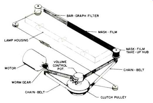
Fig. 4--Volume control mechanism.
The phono preamplifier incorporates a triple-transistor circuit originally developed for Nakamichi's 610 preamplifier.
The three devices act as a single transistor, having one-third the internal impedance of a conventional transistor.
According to Nakamichi, the power amplifier feedback configuration of the 730 overcomes the trade-off between conventional amplifiers and d.c. configured amps (good current stability for the a.c. amp at the expense of better low frequency response and lower phase error exhibited by dc amps). The 730 power amp uses a double negative-feedback circuit illustrated in block diagram form in Fig. 5c. The main feedback loop (R1, R2) does not include Cl. In addition, current through Cl is very low, since R3 is much greater than R1.
Distortion is therefore minimized by the double negative-feedback approach. The circuit also benefits from good direct-current stability, since the impedance of the negative input of the feedback amplifier is sufficiently greater than R3.
This double negative-feedback principle is used in the preamplifier as well as in the power amp section.
FM Tuner Section Measurements
Figure 6 contains plots of quieting and distortion characteristics of the tuner section of the Nakamichi 730 receiver in both mono and stereo modes, for a 1-kHz, 100 percent modulated test signal. S/N in mono reached 79 dB, while in stereo the best S/N obtained was 72 dB. Harmonic distortion was an incredibly low 0.06 percent in both mono and stereo for a 1-kHz test signal. As shown in Fig. 7, THD in both mono and stereo remained consistently low at all frequencies of interest, rising to 0.15 percent at 6 kHz for stereo. Figure 8 is a plot (taken with our spectrum analyzer) of frequency response (in stereo), stereo separation (lower curve) and stereo separation with the high-blend filter switched on. At 1 kHz, stereo separation measured 50 dB, decreasing to 41 dB at 100 Hz, and to 37 dB at 10 kHz. The 50-dB quieting point was obtained with input signal strengths of 12.4 dBf (2.3 pV) in mono and 35.6 dBf (33 pV) in stereo. Stereo switching threshold was set at 25.2 dBf (10 pV), while muting threshold was variable from 14.7 dBf (3-.0 pV) to 31.2 dBf (20 pV). Frequency response for both the 75-microsecond and Dolby 25-microsecond settings was down less than 1.0 dB at 15 kHz. The action of the Dolby circuitry is graphically displayed in Fig. 9. Note that at lower modulation levels, the high frequency response is attenuated progressively (as it should be) by the built-in Dolby FM-playback circuitry.

Fig. 5-Three basic negative-feedback circuit designs.
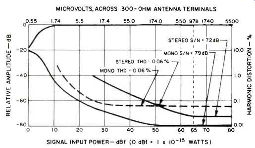
Fig. 6--Mono and stereo quieting and distortion characteristics.
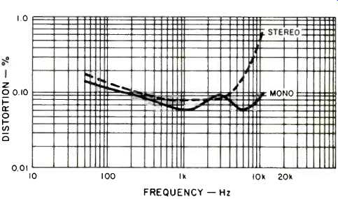
Fig. 7--Harmonic distortion vs. frequency, mono and stereo FM.
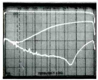
Fig. 8--Frequency response and separation. Middle curve shows decreased
separation when Hi-Blend filter is used. (Each vertical division is 10 dB.)
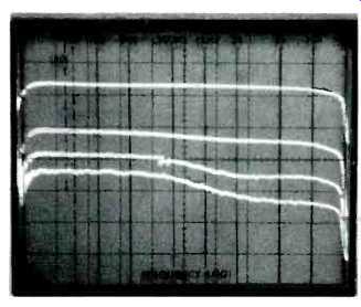
Fig. 9--Action of Dolby N/R FM circuitry at various modulation levels.
Capture ratio measured 1.4 dB, a bit better than claimed.
Selectivity measured 75 dB, while spurious, i.f., and image rejection all measured approximately 90 dB. AM suppression was exactly 55 dB as claimed. Sub-carrier products were all lower than residual noise level in stereo, and were therefore better than 72 dB down.
Amplifier Measurements
Harmonic distortion of the power amplifier section of this receiver is so low at all but near-rated power output levels that it is completely buried beneath the residual noise level and cannot be isolated by our test equipment (including our spectrum analyzer). The graphs plotted in Fig. 10, therefore, merely depict the points at which any THD could be observed. The amplifier delivered 111.75 watts for rated THD of 0.02 percent at 1 kHz. Full-power bandwidth extended from 15 Hz to 21 kHz (for rated power at rated THD), and FTC rated power measured 108 watts per channel, as opposed to the 105 watts claimed. Dynamic headroom measured exactly 1.0 dB, while clipping headroom was a modest 0.21 dB above rated output. Damping factor, measured at 50 Hz, was over 100. Figure 11 is a plot of harmonic distortion versus frequency for a rated output of 105 watts per channel into 8-ohm loads.
In an attempt to determine, even if indirectly, the sort of low-level distortion components we were dealing with here, we combined our spectrum analyzer with the facilities of our Sound Technology Model 1700B and, using the analyzer in its linear sweep mode, we first displayed a reference 1-kHz signal at rated output (full scope face peak shown in Fig. 12). We then established a new top-of-scope-face reference of -70 dB by using the distortion components output jack of the 1700B as a signal source to be fed to the analyzer and allowed the analyzer to sweep linearly from 0 to 20 kHz. The first "blip" visible to the right of the reference fundamental signals represents second order harmonic content and is 96 dB below rated output! Third order distortion is even lower, at-105 dB with respect to referenced out put. That's a third order distortion amounting to 0.00056 percent --considerably lower than your distortion analyzer (or anyone else's that we know of) can read! Tone-control action of the receiver is quite conventional, with turnover frequencies well positioned in the audio spectrum, as shown in the sweep-frequency photos of Fig. 13.
Sensitivity and the signal-to-noise measurements were made in accordance with the new IHF Amplifier Measurement Standards and may therefore be a bit difficult for the reader to interpret until some experience has been gained with these new standards. Nonetheless, on the basis of the new measurement techniques, S/N in phono measured 82 dB ("A" weighted, for a 5-mV input reference and a 1-watt output level reference). High-level-input signal-to-noise ratio, measured in a similar manner (0.5 volt input reference level), was 85 dB. Phono sensitivity (referred to 1-watt output) was 0.24 millivolts, while high-level input sensitivity was 10 millivolts (for 1-watt output). RIAA equalization was accurate (with absolutely no deviation) from 30 Hz to 10 kHz and was a miniscule-0.2 dB down at 15 kHz. At minimum volume settings, signal to noise (this time referred to full rated output) was 105 dB "A" weighted.
Using the volume preset control in its loudness contour settings in combination with a fixed setting of the main volume control of the receiver resulted in an adjustment and contour range illustrated in the sweep-frequency 'scope photo of Fig. 14. As we have commented in several previous reports, this approach to loudness compensation (also used by such firms as Yamaha and Sherwood) makes a good deal more sense than the arbitrary volume control/loudness switch arrangement supplied by most other receiver manufacturers, since it works independently of program source levels and speaker efficiencies.
Fig. 10-Power output at 1 kHz vs. distortion.
Fig. 11-Harmonic distortion vs. frequency.
Fig. 12-Spectrum analysis of harmonic distortion components of amplifier section. Reference 1-kHz signal, reaching top of display, is at-70 dB, 2nd-order distortion is approximately-% dB below rated output, while 3rd-order distortion is down more than 105 dB!
Fig. 13-Tone control range.
Fig. 14-Loudness compensation available through combined use of volume and volume preset controls.
Listening and Use Tests
Here is another receiver whose measured specifications fail to tell the whole story. To begin with, the unit is an absolute delight to use. Touch-sensor switches work positively and correctly --every time. Tune scanning speeds have been carefully calculated to be neither too fast nor too slow, and the volume control adjustment method is actually smoother than you could obtain with a conventional rotary control knob and, frankly, a lot more fun to use.
The tuner section zeros in on center-channels as accurately as any tuner we have ever adjusted manually, which means that the distortion values we read on the bench are the ones we actually obtained (and that you will obtain) when using the tuner section for actual FM program listening. Every aspect of human engineering has been analyzed and correctly interpreted in the overall design of this receiver.
As for the amplifier and its ability to reproduce music faithfully, it is certainly the equal in performance to Nakamichi's separate amplifiers which we have much admired in the past.
Bass is tight and well defined, and transient recovery is so good we found it hard to believe that the amp is not a d.c. design.
If you were to judge this magnificent receiver on the basis of watts per dollar alone, you will of course conclude that it is very high priced. Certainly you can buy 105 (or more) watts per channel for far less than $1200.00. But if you are the type of audio enthusiast who seeks a measure of elegance and sophisticated performance embodied in the Nakamichi 730 receiver, its price will be of secondary importance to you.
After all, many people thought this little company was a bit crazy when they introduced a stereo cassette deck selling for well over $1000.00 a few years ago. It was the instant success of that deck (now in its second edition) and subsequently designed products in the same category that probably enabled Nakamichi to enter the more competitive field of tuner, amplifier and now receiver manufacturing. I suspect that the same Nakamichi followers (or people like them) who "dared" to buy the first three-head Nakamichi cassette decks ever produced will feel no differently about the first, twin motor-driven receiver from that same innovative firm.
-Leonard Feldman
(Audio magazine, Nov. 1978 )
Also see:
Nakamichi SR-3A Receiver (Jan. 1987)
Nakamichi Model 630 FM Tuner/Preamplifier (Sept. 1977)
Nakamichi Reference Monitor Loudspeaker System (Dec. 1975)
Nakamichi Model T-100 Audio Analyzer (Nov. 1978)
Nakamichi cassette decks (Dec. 1982)
= = = =