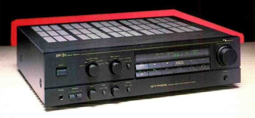
Manufacturer's Specifications:
FM Tuner Section:
Usable Sensitivity: Mono, 11.0 dBf.
50dB Quieting Sensitivity: Mono, 14.7 dBf; stereo, 37.5 dBf.
S/N Ratio: Mono, 79 dB; stereo, 74 dB.
THD at 1 kHz: Mono, 0.05%; stereo, 0.07%.
Capture Ratio: 2.0 dB.
Frequency Response: 20 Hz to 15 kHz, ± 1.0 dB.
Muting Threshold: 30 dBf.
Alternate Channel Selectivity: 55 dB.
Image Rejection: 75 dB.
I.F. Rejection: 80 dB.
Spurious Response Rejection: 90 dB.
AM Suppression: 60 dB.
Separation: 50 dB at 1 kHz, 46 dB at 100 Hz, 46 dB at 10 kHz.
AM Tuner Section:
Sensitivity: 53 dBµ/m (dB referred to 1µV/m).
S/N Ratio: 52 dB at 90 dBµ/m.
THD: 0.3% at 90 dBµ/m.
Selectivity: 20 dB.
Amplifier Section:
Power Output: 45 watts per channel, 8-ohm loads, 20 Hz to 20 kHz.
THD: 0.1%.
IM Distortion: 0.15%.
Dynamic Headroom: 1.5 dB.
Headphone Output: 105 mW (40 ohms).
Peak Output Current Capability: 18 amperes per channel.
Input Sensitivity: MM phono, 0.37 mV; MC phono, 8.9 µV at 32-dB gain, 24.0 µV at 24-dB gain; high level, 30 mV.
Phono Overload: MM, 140 mV; MC, 3.0 mV at 32-dB gain, 8.0 mV at 24 dB gain.
Phono S/N Ratio: MM, 80 dB; MC, 73 dB at 32-dB gain, 72 dB at 24-dB gain.
Tone Control Range: Bass, ± 10 dB at 20 Hz; treble, ± 10 dB at 20 kHz.
Loudness Contour at 30 dB: +10 dB at 20 Hz, +6 dB at 20 kHz.
Subsonic Filter (Phono Only): -12 dB per octave, below 20 Hz.
General Specifications:
Power Requirements: 120 V a.c. 50/60 Hz; 270 watts maximum.
Dimensions: 16 15/16 in. W x 3 15/16 in. H x 14 9/16 in. D (43 cm x 10 cm x 33 cm).
Weight: 18 lbs., 10 oz. (8.5 kg).
Price: $599.
Company Address: 19701 South Vermont Ave., Torrance, Cal. 90502.
This is not the first time Nakamichi has attempted to broaden its product mix by introducing components other than the tape decks that have made the company justly famous. Using the "Stasis" technology which it licensed from Threshold Corporation (more about this in a moment), Nakamichi has introduced a pair of receivers, the higher powered of which is evaluated here. By today's standards, the SR-3A's 45-watt-per-channel power rating is only moderate, but as my listening tests revealed, you can't always equate steady-state power output ratings with loudness levels. The SR-3A sounds more powerful than its rating suggests. By the same token, you can't judge how clean an amplifier will sound simply by reading its THD or IM specifications. The distortion numbers for the amplifier section of the SR-3A are not among the lowest I've seen in modern receivers, yet the sound produced by this carefully designed component seemed cleaner than what I've heard from receivers or amplifiers boasting THD figures that have several zeros to the right of the decimal point.
The Stasis Concept
In an amplifier employing Stasis topology, two amplifiers drive the load. The first is an extremely high-quality, low distortion, low output-impedance amplifier with relatively modest current capability. The other is a high-impedance, high-current "bootstrap" arrangement. Because of the impedance difference, the low-impedance amp determines the voltage across the load while the high-impedance amp supplies the needed current. To the extent that the high impedance amp distorts high-level signals, the low-impedance amp delivers current to correct the error. However, since this correction current represents a negligible amount of power, the low-impedance amplifier operates in a virtual "stasis" or state-of-equilibrium condition and generates almost no distortion. And since this is the section that determines overall distortion, the amplifier as a whole is as good as the Stasis section itself. This arrangement also eliminates the need for overall loop or global feedback. (Editor's Note: For Threshold's own explanation of the Stasis circuit, see our "Equipment Profile" of the Threshold SA/1 amplifier elsewhere in this issue.) The SR-3A receiver incorporates many other features worth noting. The power supply employs a multiple-winding power transformer with separate rectifiers and regulators for audio, tuner, display, and video circuitry. An "isolated ground sub-regulator" system is used in order to prevent interstage interference by eliminating ground currents.
The phono preamplifier circuit is a low-noise, high-trans conductance, FET design. Its moving-coil cartridge input has selectable gain to accommodate low- and high-level MC cartridges, and the RIAA equalization network is direct coupled for accurate response over the entire audio band.
A steep-slope subsonic filter in the phono section is defeatable, as are the loudness-contour circuit and the bass and treble tone-control circuits. Video inputs as well as a video monitor output are provided so that the receiver can serve as the main control center for an integrated audio/ video component system. Extensive protection circuitry guards against d.c. leakage, overload, and overheating.
The tuner section is a frequency-synthesized quartz-lock design with 10 available presets plus manual and auto-seek tuning for both AM and FM signals. The front-end employs twin-varicap diode tuning (equivalent to four-gang tuning) and a dual-gate MOS-FET front-end r.f. stage. A tuner buffer amplifier isolates the tuner from other program sources.
Associated with the tuner section is a panel display that shows the band (AM or FM), tuned-to frequency, stereo signal reception, signal strength, quartz-lock status, and auto-seek tuning status.
Control Layout
Next to the power switch at the left of the front panel are separate "Tape/VCR Monitor" and "Input Selector" rotary controls. The tuner display area is to their right, and two rows of six angled pushbuttons are arranged below the display. The upper buttons, from left to right, take care of preset memorization, AM and FM band selection, tuning mode selection, and down and up tuning (manual or auto). The lower row of buttons is used for memorizing and accessing the 10 station presets, any of which may be used for AM or FM. This can be accomplished with only six buttons since five of them are each responsible for two presets, with the sixth acting much like a typewriter "shift" key, selecting the first five presets or the second five. Dual concentric master volume and balance knobs are at the extreme right end of the panel.
Secondary controls, located along the lower left section of the panel, include a stereo headphone jack, speaker selector switches, bass and treble tone controls, a tone-defeat switch, and the subsonic filter on/off switch. A loudness on/ off switch is at the extreme lower right.
FM and AM antenna terminals are on the rear panel. A separate AM loopstick antenna and mounting hardware are provided for those who don't want to install an outdoor AM antenna (and that means most of us). A small slide switch selects 24- or 32-dB gain levels for the moving-coil inputs.
The usual audio input jack pairs are centrally positioned on the rear panel, along with not-so-usual video inputs and a video monitor output. Provision is made for connecting both the video input and the video output (for playback) of a VCR, as well as the associated audio input and output signals of that same VCR. Two sets of speaker terminals are near the right end of the rear panel, along with a pair of switched a.c. convenience outlets.
Tuner Measurements
Nakamichi supplies a matching transformer in case you don't want to use a coaxial antenna transmission line. Because my FM generator has only a 50-ohm output and a 50/ 300-ohm matching transformer, I had to use that transformer plus the Nakamichi transformer to get a proper match for the SR-3A's 75-ohm input. I am quite sure that all of this stepping up and stepping down resulted in some signal loss, which would explain why I couldn't measure better than about 14 dBf for mono usable sensitivity, as against the 11.0 dBf claimed by Nakamichi. When I increased signal inputs above these low levels, my results and Nakamichi's claims agreed in almost every other respect. In most instances, in fact, my sample did a bit better than claimed.
For example, Fig. 1 shows how quieting and distortion improve with increasing signal level. Signal-to-noise ratio for mono, with 65-dEf signals applied, was 79 dB, exactly as claimed. In stereo, S/N measured 75 dB or a bit better than claimed. THD at 1 kHz measured only 0.035% in mono and rose negligibly to 0.045% in stereo. Both figures are better than the manufacturer's specifications.
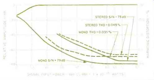
Fig. 1--Mono and stereo quieting and distortion characteristics, FM tuner
section.
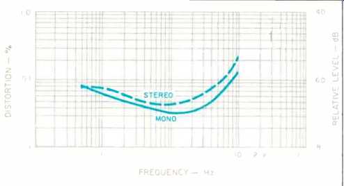
Fig. 2--THD vs. frequency, FM tuner section.
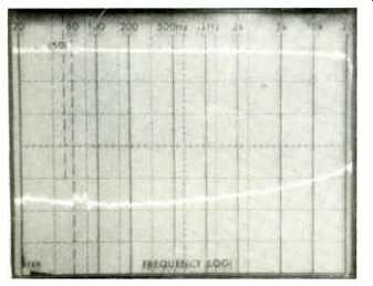
Fig. 3--FM frequency response (top trace) and separation vs. frequency.
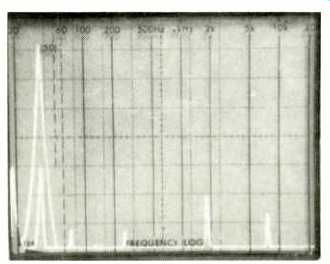
Fig. 4--Separation and crosstalk components for a 5-kHz modulating signal,
FM tuner section.
Figure 2 plots harmonic distortion versus frequency for the FM tuner section. Unlike the many tuners which exhibit very high distortion levels in stereo as higher and higher frequencies modulate the FM carrier, this section's THD at 6 kHz in stereo was a mere 0.1%, only marginally higher than in mono. Even at 10 kHz, THD in stereo was only 0.23%. Frequency response was well within the 1.0-dB tolerance claimed by Nakamichi, being down only 0.7 dB at 15 kHz.
Figure 3 shows FM frequency response as well as stereo FM channel separation. At 1 kHz, separation from left to right measured an impressively high 52 dB; it was 48 dB from right to left. At 100 Hz and 10 kHz, left-to-right separation measured 51 and 42 dB, respectively, and right-to-left separation was 47 and 40 dB, respectively.
Figure 4 is the usual spectrum analysis 'scope photo which superimposes a 5-kHz, 100% modulated signal seen at the left output terminal and the crosstalk and distortion components seen at the output of the unmodulated opposite channel. The two components at the right of the display are sidebands at 33 and 43 kHz (5 kHz on either side of the suppressed 38-kHz subcarrier). The tuner section's 19- and 38-kHz rejection was a satisfactory (if not outstanding) 64 dB, and SCA rejection was 60 dB. Muting and stereo threshold both measured around 30 dB, and 50-dB quieting was 16 dBf in mono and 40 dBf in stereo. These last figures are again attributable to the signal losses in the transformers I had to use for the measurements. I have no doubt that with a direct 75-ohm to 75-ohm connection I would have been able to obtain Nakamichi's better 50-dB quieting and usable sensitivity figures.
I.f., image, and spurious-response rejection were all slightly better than claimed, and selectivity measured exactly 55 dB, as claimed. Capture ratio was 1.8 dB, and AM suppression measured 62 dB. If you glance back at the manufacturer's published specifications for the SR-3A's AM tuner section, you'll notice that, like so many receiver makers, Nakamichi doesn't tell us about AM frequency response. Figure 5 offers a good reason for this omission, and the less said about it the better. I can't for the life of me understand why companies go to the trouble of designing AM tuner sections with nice r.f. stages, low distortion, and even decent signal-to-noise ratios (by AM standards), but fail to extend the response even out to a bare-bones 5 kHz or so!
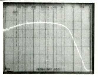
Fig. 5--AM frequency response.
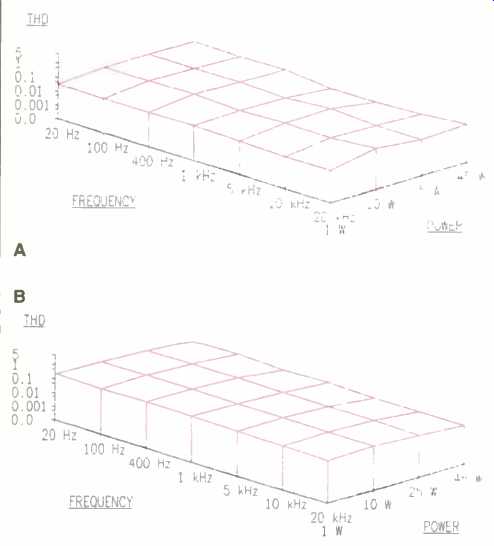
Fig. 6--Power output vs. frequency vs. THD, with 8-ohm (A) and 4-ohm (B)
loads.
Amplifier Measurements
The Stasis power amplifier section delivered 53 watts of continuous power at mid-frequencies for its rated 0.1% THD when coupled to 8-ohm loads. Even at the frequency extremes, available continuous output power was higher than claimed, with 50 watts per channel produced at 20 Hz and 53 watts per channel at 20 kHz. Backing off to the rated 45 watts-per-channel level, I measured THD of 0.02% at 1 kHz, 0.05% at 20 Hz, and 0.055% at 20 kHz. "Three-dimensional" plots of power output versus frequency versus harmonic distortion levels are shown in Fig. 6. Power output at 4 ohms was not all that much higher than it was at 8 ohms-at least on a continuous basis. Maximum output for 0.1% THD at mid-frequencies was 59 watts per channel. Dynamic headroom, on the other hand, was an impressive 1.9 dB with an 8-ohm load, which means that for short signal peaks, such as those encountered on music recordings, this amplifier section can produce as much as 70 watts per channel. No wonder it sounded "louder" than it measured on the bench! Damping factor was a low 20, no doubt because of the fact that the Stasis circuit employs no overall loop feedback to lower the amplifier's output impedance. In my view, a damping factor of 20 is adequate for most of the popular speakers likely to be used with this receiver, so I wouldn't worry about it too much.
As for the SR-3A's preamplifier/control section, Fig. 7 shows how Nakamichi has designed the tone controls. Notice that even with bass and treble controls in their full boost or cut positions, mid-frequency response remains totally unaffected. This is the way good tone controls should work, and it's no surprise that they do so on this carefully and thoughtfully designed receiver. Figure 8 shows the action and response of the loudness compensation circuit at various settings of the master volume control.
The subsonic filter, when turned on, attenuated phono response by 3 dB at 20 Hz, but at 10 Hz, response was already down more than 14 dB. The RIAA equalization from 20 Hz to 20 kHz was accurate to within 0.5 dB. High-level input sensitivity for 1 watt output measured exactly 29 mV. Phono input sensitivity for the same 1 watt output measured 0.44 mV for the moving-magnet inputs, and 9 or 24 µV for the moving-coil inputs, depending upon the setting of the MC gain switch.
Signal-to-noise ratio for the high-level inputs measured 86 dB below 1 watt, referred to 0.5 V input. With the volume control set at minimum, noise was 90 dB below 1 watt; referred to rated output, it would work out to just over 106 dB. Phono S/N measured 84 dB for the MM inputs, referred to 5.0 mV input and 1 watt output. The MC input S/N was 72 or 75 dB (referred to 0.5 mV input and 1 watt output), again depending upon the setting of the MC gain switch on the rear panel. Phono overload for a 1-kHz signal measured 150 mV for the moving-magnet inputs, 16 and 6 mV for the MC inputs. Overall frequency response via the high-level, tape, or audio/video inputs was flat to within 1.0 dB from 5 Hz to 75 kHz and within 3 dB from 2.5 Hz to 110 kHz.
I checked the tracking accuracy of the master volume control and found that from 0 dB (maximum setting) down to -60 dB, there was a tracking error of less than 0.5 dB. Of course, if you turn down the control still further, the error tends to increase, but you're not likely to do much listening at that level.
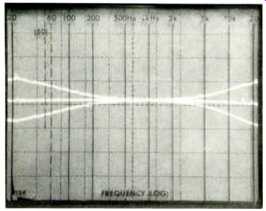
Fig. 7--Tone-control characteristics.

Fig. 8—Loudness compensation control characteristics.
Use and Listening Tests
My overall reaction to the SR-3A is that, like all Nakamichi components I've evaluated in the past, the emphasis is on good internal design rather than on superfluous (and often undesirable) external frills and extra switches or buttons.
Still, all the functions you are likely to ever want in a receiver are included, and I get the feeling that each switch and circuit was given careful thought as to its necessity, its design, and its position on the front panel.
The SR-3A, if judged solely on the basis of watts per dollar, is not likely to be the universal choice of the casual listener. On the other hand, after doing some serious listening, I concluded that the Stasis technology does make for the very clean-sounding amplifier which advanced audiophiles choose. Even with its higher-than-usual dynamic headroom, the power of this receiver should be matched with fairly efficient loudspeaker systems. Fortunately, there are plenty of good ones available these days; speakers with a sensitivity rating of 90 dB or better are what you should look for as most suitable for use with the SR-3A. Connected to a good outdoor antenna (and yes, this time with a 75-ohm coaxial transmission line), the tuner section pulled in all of the stations I normally expect to receive with a good, sensitive unit. I might have liked a somewhat lower stereo threshold; by the time stereo switches on, signal-to-noise ratios are quite acceptable, and I suspect that a somewhat lower switching point could have been tolerated by most listeners. There's no way to defeat the muting threshold while you are in the stereo mode. Muting threshold is set at about the same point as the stereo threshold, so if you want to do a little serious DX-ing on the FM band, you'll have to settle for mono.
I was very pleased with the phono performance too, especially the action of the subsonic filter. It didn't intrude upon musical content at all, but it noticeably cleaned up the sound of some of my LPs when they were played on a turntable known to have very poor signal-to-noise (call it signal-to-rumble) figures. If your only experience with Nakamichi is with their indisputably superb cassette decks, you're in for a pleasant surprise when you audition this receiver or its lower priced, 30-watt-per-channel companion, the SR-2A.
-Leonard Feldman
(Source: Audio magazine, Jan. 1987 )
Also see:
Link | --Nakamichi Model 730 Stereo FM Receiver (Dec. 1978)
Nakamichi Model T-100 Audio Analyzer (Nov. 1978)
Nakamichi cassette decks (Dec. 1982)
= = = =