The days of the color high-voltage regulator as we've known it in tube receivers has all but vanished. Its replacement is a limiter that acts not only from a high-voltage increase, but also exerts direct control on cathode ray beam current, a much more satisfactory procedure since both high voltage and beam current are simultaneously affected and receiver regulation is considerably improved. It's been common practice in the days of the 6BK4 to rotate the brightness control and watch the filament (if you could see it) of the shunt regulator to determine if it glowed as beam current increased.
Even in the newer tube types, regulation wasn't that good, so as the brightness limiter type of circuit was developed, there has appeared a rather simple and certainly better beam current-high voltage type limiting.
With the brightness limiter came the two, three, and four section voltage doubler, tripler, and quadrupler used mainly by Magnavox in its new solid-state receiver, Zenith and Sylvania in their latest models, and RCA in the CTC46, 49, 54, etc., Series, respectively. This high-voltage arrangement has permitted smaller, lower voltage HV output transformers, less loading on the output circuits, and very adequate and predictable high voltage. Motorola, meanwhile, has stuck to the single-ended output and stacked solid-state rectifier for its transistor sets, and this operates well, too. In fact, with new horizontal output transistors being developed at a faster rate than ever, economics may well dictate a single-ended output that will bring the hefty high-voltage transformer right back again.
Also, at this writing there appears to be a considerable movement underway to develop some type of oscillator to drive all voltage supplies to provide better regulation, less filtering, possibly less space, and certainly far better efficiency at probably reduced cost. We'll look at some typical and proposed examples in the next section on low-voltage power supplies.
Accordingly to Jim Hornberger, Delco Electronics has developed a horizontal deflection circuit (Fig. 10-1) for a 25-inch, 110-degree color tube that supplies 25 kilovolts from a regulated 240-volt power supply. Two series-connected DTS 804 transistors are driven by a 2N3439 and the secondaries of T1 and T2. The transformer is tuned to the fifth harmonic and delivers better than 1.5 kilovolts from 0 to 1.5 milliamperes beam current. The DTS-411 insures a regulated 240-volt DC source, while the DRS-114C diode protects the transistors from excessive HV transients. The 150-meg bleeder resistor following the Varo doubler gives better low-current regulation and allows the picture tube capacitance to discharge easily when the receiver is turned off, leaving no center white spot or trace. The DRS-114D diodes are the damper (top) and clamp (bottom), respectively. A 19-inch 110-degree tube, according to Delco's Hornberger, can use only a single DTS-804 and drive the CRT at 20.5 kilovolts easily.
VACUUM TUBE HIGH-VOLTAGE GENERATORS
The horizontal sweep system (Fig. 10-2) has a number of functions it must execute, including high voltage, B-boost, dynamic convergence correction, pincushion correction, and blanking, but the most important of these is generating a linear sweep current through the horizontal deflection yoke windings. For without this sweep, there could be none of the others.
Fig. 10-3 should help you understand the operation of the output tube, damper, and deflection yoke as events occur during the line trace and retrace 63.5-microsecond interval.
This illustration, you will notice, represents both voltages and currents, a none too subtle suggestion that some manufacturer should get busy and make a fairly simple, not too expensive current probe that will work with at least the better oscilloscopes, say, those with 1 meg impedances and about 30 pf shunt at the inputs. If more SCR RCA-type systems are adopted, not having a current probe will eventually lose you, believe me. There are just too many reactors, coils, and transformers to cope with.
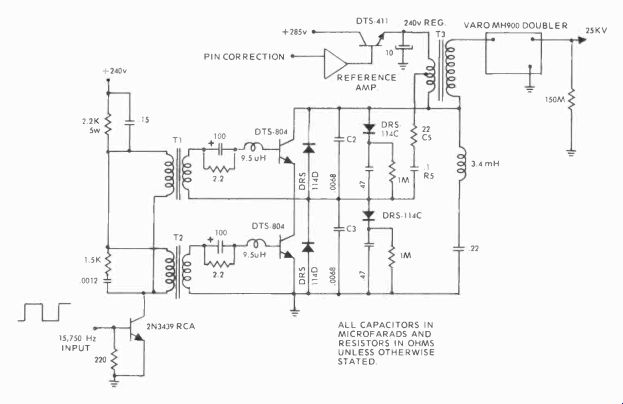
Fig. 10-1. Delco developed HV driver and output circuit for 110-degree 25-inch
CRTs that will probably be seen in the U.S. between 1973 and 1974. (Courtesy
Jim Hornberger)
Fig. 10-2. A vacuum tube high-voltage subsystem with yoke and pincushion
transformer circuits. The drawing illustrates the reason for center curvature
and amplitude pincushion sweep corrections.
In working with the horizontal subsystem, there are several things you should always remember: 1) retrace is caused by the magnetic field reversal in the HV-yoke coils following output tube cutoff; 2) following retrace, and for the purpose of damping the HV-yoke oscillations, the damper conducts and helps move the trace from a resting position on the left side of the screen to its center; 3) the output tube plate...
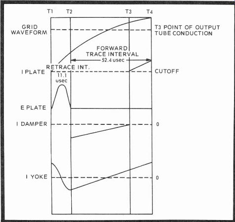
Fig. 10-3. These curves show one cycle of horizontal output beginning with
retrace and ending with cutoff. (Courtesy Ray Guichard, Magnavox)
... voltage rises during the time the grid goes heavily negative (Ti in Fig. 10-3), since the tube is cutoff; 4) As the grid (not the plate) comes out of cutoff (T2) and toward drive, the trace interval begins, the tube plate voltage is clamped, the damper current begins a linear rise, carrying the beam from center to the right edge; 5) yoke current is also linearly increasing and, when the output tube grid reaches the point of conduction (T3), the output tube plate current rises, the damper reaches 0 and cuts off, and the yoke current continues to increase linearly until time T4 and complete output tube cutoff.
Observe that the yoke current during retrace (T1 to T2) is almost a sine wave and it develops an oscillation frequency of about 70 kHz. Also, realize that even though the grid leak bias on the grid of the horizontal output tube begins to dissipate by time T2, it is not until the grid coupling capacitor charges to time T3 that the output tube actually begins conduction. This, then, is how all single output horizontal subsystems operate.
The SCR types are somewhat different, since they have no damper, simply trace and retrace complements formed through certain coils, RC time constants, SCRs, and diodes.
In the plate of the V104 damper, shown in Fig. 10-2, you will see a 5.6 microhenry coil and then a horizontal efficiency parallel circuit. The coil and its two capacitors help linearize the overlap damper-output tube currents as they pass through half-way or zero points driving the deflection yoke-the I yoke 0 point shown in the lower curve, Fig. 10-3. A check for such linearity is made at the output tube's cathode with a meter, and the efficiency coil is adjusted for minimum cathode current, often something less than 200 milliamperes.
The focus rectifier simply supplies a rectified high voltage to focus the beams in the cathode ray tube. There is a coil adjustment, since one cathode ray tube will vary from another. The various boost and boosted voltages are generated from different taps on the flyback transformer, rectified, filtered (usually) and then dispatched to their various sub scriber circuits. The 850-volt boost is the reference, since any varying load on the high voltage makes the boost voltage change in the same direction.
The cathode of the regulator goes to the B+ 405-volt supply. When high voltage drops, due to beam current demand, the grid of the HV regulator becomes less positive, the regulator does not conduct as much (becomes a higher resistance) and the high voltage rises due to lighter loading.
When beam currents decrease, the boost voltage rises, causing the regulator to conduct more heavily and load the high-voltage output so that HV is dropped in accordance with the magnitude of the boost supply.
Notice the arrow to PW700 MM. This extension couples video to the grid of the regulator so that when large white areas are being televised, the regulator grid sees the same polarity picture the CRT does, and the high voltage remains steady. If this coupling were not made, white scenes would immediately draw extra beam current and load the high voltage accordingly. The high-voltage adjust is simply a DC voltage divider, with the arm at ground potential.
The pincushion circuit may operate with simply a passive transformer, as shown here, or with active tube and transistor stages that also supply dynamic scan correction to the deflection coils. If it were not for this circuit, center curvature (Fig. 10-3) and amplitude beam corrections could not be made in the larger rectangular tube receivers, and the resulting image would be considerably distorted. Horizontal currents supply side pincushion correction, with vertical currents operating on the top and bottom amplitude and phase. One vertical-horizontal voltage modulates another, as shown in waveforms 14 and 15, so that the tube extremes are affected much more than the center, and the collective sweeps are compensated accordingly.
Pincushion transformer and potentiometer adjustments can easily be made with a stable crosshatch generator. Output waveforms, as you can see, appear either as a bow tie or an ellipse, depending on sweep rate adjustment of the oscilloscope. What you should remember specifically about pincushion correction is that the yoke current is shaped to linearize the sweep rather than individual beam bending, as done by the electromagnetic convergence circuits.
ZENITH'S HIGH-VOLTAGE OUTPUT WITH VOLTAGE TRIPLER
The circuit in Fig. 10-4 is standard in the 4B25C19 (B4030-C4030) Zenith chassis series. The usual grid leak biased horizontal output tube supplies drive for the flyback, yoke, saturable reactor pincushion transformer, and AGC-AFC video-sync limiting and frequency correction circuits. The output connects to the primary of the horizontal output transformer, two windings above the V204 damper cathode tap. The yoke connects at the third and fourth tap-offs, and the pincushion reactor to the fifth. The output tube drive waveform, this time a trapezoidal, is illustrated by waveform 16 (Fig. 10-4), with the AFC negative-going pulse shown by waveform 17. The most interesting waveforms, however, are those illustrated by 54 and 55.
A 500-volt positive pulse is coupled through C264 to add or subtract from the bias supplied through HV adjust R332, the 270-volt bus and grid action of the horizontal oscillator drive waveform. An increase in the amplitude of this pulse will cause varactor R333 to decrease in value, limiting the positive DC to the output grid and lessening conduction. A decrease in high voltage will cause an opposite reaction, with R333 in creasing in value, thus allowing the positive grid voltage to become greater since there is less divider action between R329 and R333. Consequently, the output drive becomes greater, supplying additional high voltage to make up for the drop.
The output HV inductor in this receiver is virtually an auto-transformer supplying various potentials at the tap points and B-boost through C268, one end of which is tied to the 270-volt supply, with additional current supplied by the damper for generation of the extra 500 volts, 780v being the boosted supply. The transformer, however, is smaller than the usual flyback, and its series inductance generates only about 8.33 kilovolts upon magnetic flux reversal.
The high-voltage output is coupled to the tripler circuit shown at the bottom of Fig. 10-4. This "stack" can either have an input capacitor between the flyback (usually does) and the tripler, or a capacitor to ground from terminal 8. In this arrangement, C1 charges positively through D1 on the initial HV output, but divides with D2-C2, so that both capacitors have 4 kilovolts across them. The second HV series charges C1 to 8 + 4, or 12 kilovolts, but C2 divides, and they each then store 6 kilovolts. On the third round pulse, C1 and C2 now have 8 kilovolts across them, and the second branch of the tripler begins to charge. This branch consists of capacitors C3 and C4, plus diodes D3 and D4, and they rectify and charge the two capacitors in steps just like the initial stack. Finally, the third diode rectifies and charges the capacitor, but the input potential is 16 kilovolts, since the first two stacks are 8 kilovolts each. Since C5 has no other divider capacitor with which to equalize, it retains the 16 KV plus 8 KV, and the total output applied to the picture tube is a full 24 kilovolts. Notice that the voltage is cumulative across all three stacks so that a voltmeter placed between output and ground will read the fully developed voltage, including that of the flyback trans former. The small schematics beneath the subsystem diagram show two tripler versions with slightly different divider networks and, in the first, a capacitor between the focus tap and brightness limiter.
A BRIGHTNESS LIMITER CIRCUIT
In the B-C4030 there is also a brightness limiter that controls beam current as a function of high voltage (Fig. 10-5).
A beam current sampling out of the voltage tripler is connected through a potentiometer to the input of Q204, a limiter transistor, which is protected by zener diode CR214. If there is a beam current increase, the current through the arm of tripler-brightness potentiometer R338 (Fig. 10-4) will also increase and cause a positive voltage drop, turning on the brightness limiter. Q204 is a little more than a switch, and it will turn on more or less, supplying a resistive ground path for the base of second video amplifier Q205, reducing its conduction and output, and so lessening the cathode ray tube's beam current.
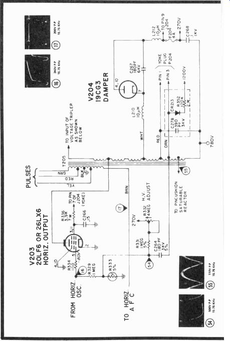
Fig. 10-4. Zenith's C4030 horizontal output and high-voltage tripler circuits,
which generates 24 kilovolts.
Positive horizontal blanking is applied through CR203 to the emitters of Q207 and Q205 which are blanked by the positive-going horizontal pulse at horizontal retrace time.
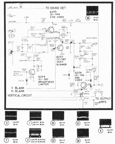
Fig. 10-5. A Zenith beam current brightness limiter circuit that controls
the second video amplifier to prevent excess HV current drain.
Vertical blanking switches on the vertical blanker back-bias the second video amplifier at vertical blanking time. The third video amplifier supplies the normal-setup switch that collapses the vertical sweep and shuts off video during color temperature adjustments.
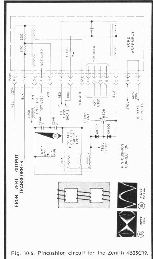
Fig. 10-6. Pincushion circuit for the Zenith 4B25C19.
PINCUSHION CIRCUIT
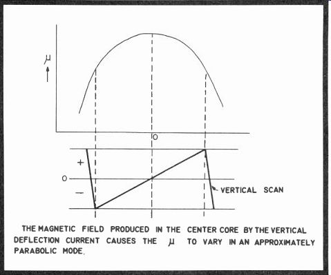
Fig. 10-7. Relationship of p (mu) to the scan frequency. THE MAGNETIC FIELD
PRODUCED IN THE CENTER CORE BY THE VERTICAL DEFLECTION CURRENT CAUSES THE
p TO VARY IN AN APPROXIMATELY PARABOLIC MODE.
This Zenith pincushion circuit (Fig. 10-6) utilizes a saturable coil technique consisting of specially shaped ferrox-cube E-cores with windings on all three limbs (or cores). The center winding, which is used for control purposes, is connected in series between the vertical deflection coils, while the outer windings (being the controlled load impedance) are connected in series with the horizontal deflection coils and in series with each other. Connecting the two outer windings in series and in the opposite direction minimizes the interaction between the control and load windings. However, interaction remains low only as long as the core saturation is very low. At higher core saturations, interaction does occur and is used to obtain the required top-bottom and side pincushion corrections simultaneously.
The vertical deflection sawtooth current flowing through the center core winding produces a variable magnetic flux in the core. During one vertical scan, the permeability (II) will vary from a low level at the start of the vertical scan to a high level at mid-scan and again to a low level at the end of the vertical scan. This change in permeability has a parabolic type curve representation (Fig. 10-7). The variation of permeability causes a change in the inductance value of the outer windings. Thus, the amplitude of the horizontal deflection current will vary in an approximately parabolic mode with vertical scan which will counteract pincushion distortion at the raster sides.
During one horizontal scan period, the momentary value of the vertical deflection current can be considered to be constant. Also, at the time of a horizontal scan through the center of the picture, the vertical deflection current is zero.
The currents at the horizontal frequency flowing through the outer windings of the saturable reactor produce a flux in the core that passes only through the outer cores but not the center core. However, this is true only if the outer cores are equally saturated. Dependent on the vertical deflection current flowing through the center core winding being positive or negative, this current will intensify or weaken the saturation in one of the outer cores with respect to that in the other one.
Due to these differences in saturation of the outer cores, the flux at the horizontal scan frequency will also partly pass through the center core.
THE AMPLITUDE OF THE HORIZONTAL DEFLECTION CURRENT VARIES IN AN APPROXIMATELY PARABOLIC MODE WITH THE VERTICAL FREQUENCY.
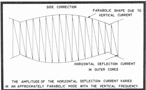
Fig. 10-8. Pincushion side correction currents used in the 4625C19.
The intensity of this flux is dependent upon the intensity of the flux at the vertical frequency (Fig. 10-8). The polarity of this flux is dependent on the polarity of the vertical deflection current. Thus, a flux at the horizontal frequency, which is modulated in amplitude and phase at the vertical frequency, passes through the center core and induces a voltage which is an approximately sawtooth shaped waveform. Since this voltage acts in series with the vertical deflection coils, it causes parabolic waveform currents at the horizontal frequency in the vertical deflection coils. The currents have maximum amplitude at the top and bottom of the picture, but are zero at the center.
However, the polarity of this "correcting" voltage is such that the original pincushion distortion would be increased.
Therefore, the polarity of the induced voltage in the center core is reversed by means of two capacitors (0.1 mfd) in series between the vertical deflection coils, and the induced voltage tapped from between the coils and capacitors. Since a voltage (phase) difference exists between the voltage across a coil and one across a capacitor, the proper polarity is obtained.
The amplitude of the vertical frequency correction current (top-bottom correction) is controlled by potentiometer R307 (30 ohms) and phase controlled by the adjustable coil, L208. Proper adjustment can be achieved by setting the amplitude control for the desired amplitude for straight lines across the top and bottom of the raster and then adjusting the coil for the proper phase. In some instances, it may be desirable to work back and forth between the two adjustments a few times for optimum settings.
Horizontal centering is accomplished by applying the AC sweep current (sawtooth) through a bridge circuit in series with the deflection yoke. The bridge consists of R308, CR206 and CR207. When the arm of the control is set at its center, an equal amount of positive and negative current flows through each diode and the control. Since the current paths are equal and opposite, cancellation occurs. However, if the arm of the control is set at either end of the control, it becomes shorted by one or the other diode, depending on which direction the arm is rotated. Thus, current in one direction will be greater than in the opposite direction. Either more positive or more negative current will be permitted to flow.
HIGH-VOLTAGE BLOCK DIAGRAM
Now that we've covered some of the preceding sophisticated circuits, we are ready to tie the entire package together and show what a block diagram of the complete high voltage system looks like (Fig. 10-7).
As you see, the output not only drives the flyback but supplies the deflection yoke, pincushion transformer, feed back to the yoke, with vertical circuit inputs to both pincushion and vertical deflection coils of the yoke itself. The high voltage may be rectified by a single tube, stacked semiconductor diode, or it may be developed from a smaller flyback trans former, then doubled, tripled, or quadrupled for a 20- to 27- kilovolt output. The horizontal AFC is usually supplied by a winding on the flyback, while the doubler-tripler has an output to control conduction of a brightness limiter that acts on the video chain to limit beam current.
The damper (in any system besides RCA's) is placed before the flyback. Actually, the damper is in the primary of the flyback transformer on both tube and semiconductor systems and, although slightly different in circuit con figuration, does the same basic job in both, except that it may or may not develop boost voltage, depending on its placement in the circuit. Where boost is generated, any (damper) diode will have to be suspended between the flyback and a high DC voltage to develop the additional high potential.
At no point, you may have observed, is there anything said about a filter capacitor for the rectified high-voltage pulse. In reality, there's a big one that amounts to about 500 pf, and it consists of the aquadag coating on the cathode ray tube. In older B&W receivers, there are still some large ceramic 20 kilovolt "barrels" to be found that need a change now and then. But in color receivers, a new HV rectifier filter means a new cathode ray tube, unless you want to innovate, and this indeed is a mite more expensive. The good old RA112-113 series of monochrome Dumont sets used to have three 470-pf 10 KV capacitors, originally oil filled, that shorted every so many years, cutting off high voltage, and producing many an interesting repair job. Capeharts used to burn up HV shunt capacitors and flyback transformers, and RCA's did their share of shorting deflection yokes and damping capacitors.
RCA'S HIGH-VOLTAGE & PINCUSHION CIRCUITS
When SCR102 is triggered (Fig. 9-9), the retrace resonant circuit is completed and the energy stored in C412, C413, and C414 causes electron flow to continue downward through the yoke, rapidly cutting off SCR101.
Resonance causes the yoke current to decay to zero and reverse, cutting off SCR102 and turning on CR102. At this instant, scan is at the center of retrace. Current increases until it reaches a maximum, driving the scan to the left side of the screen, but it cannot reverse again because gate voltage no longer is present on SCR102. The large current flowing in the yoke at the end of retrace takes the only path available, through CR101. This, of course, was the condition assumed at the beginning of this summary.
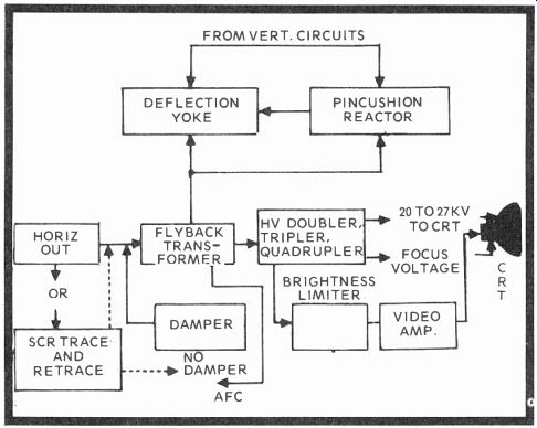
Fig. 10-9. Block diagram of a modern high-voltage sub-system.
The high-voltage transformer is connected parallel to the yoke circuit. During scan time either SCR101 or CR101 is conducting, thus shorting the primary so that very little energy can enter. However, during retrace the flyback voltage pulse drives the transformer primary, and the transformer converts this voltage to a higher voltage, which is used to drive the quadrupler and screen power supply. Energy transfer is optimized by tuning the transformer to the third harmonic of the retrace pulse. This is the function of L401.
Scan width and high-voltage level are sensed by sampling the voltage developed across C408 and C409 during scan time.
An increase in scan width and high voltage increases the collector current of Q401. This further saturates T402, decreasing its inductance and increasing the resonant frequency of the power input resonant circuit. Since this causes the voltage at the anode of SCR102 to crest sooner and decay further before the next retrace begins, there is less energy available for scan and high voltage during the sub sequent retrace and trace cycle. If scan width and high voltage tend to decrease, they are stabilized in the same way, except, of course, all processes are reversed.
To overcome side pincushion, the horizontal scan must be increased when the vertical scan is near the center of the raster. In earlier model RCA color receivers, this correction was accomplished by passive components, but because of the wider deflection angle used in the CTC49 a more sophisticated means of correction is necessary. Since the high-voltage regulator of this chassis also controls the scan width, side pincushioning may be corrected conveniently by providing a second input to the regulator. This input to the regulator is derived from the vertical deflection circuits and processed by the circuit shown in Fig. 10-10.
Q402 may be considered as a resistor which allows current flowing towards the high-voltage control to take either of two paths. One of these is through CR408 and the emitter-to-base junction of Q401, which is the normal voltage-regulating current previously described. The second path is through CR405 and the collector of Q402. Obviously, if more current flows through Q402, less flows through Q401, causing the high voltage and scan width to increase.
To correct side pincushioning, then, it is necessary only to increase the forward bias of Q402 when vertical scan is near the center of the raster and decrease it when the vertical scan is near the top and bottom. One output from the vertical deflection system is fed to the base of Q402 by way of R416 and R415 and another arrives via R417. These samples of vertical deflection signal are shaped into a parabolic waveform which reaches its maximum positive potential at vertical mid-scan.
Two inputs taken from the horizontal deflection system are used to optimize the high-voltage regulation and pin cushion correction. The first of these is taken from terminal D (see Fig. 10-11) of the high-voltage quadrupler, via R115, and reaches the base of Q402 by way of R426 and R419. The purpose is to allow the regulator system to "measure" the beam current and regulate high voltage more accurately.
The second input is taken from terminal C of the quadrupler and reaches the base of Q402 by way of an adjusting potentiometer, R428. This input samples the high voltage by means of the capacitive voltage divider made up of C426 and the capacitors in the quadrupler, and compensates for phase shift of the side pincushion correction voltage, which is the result of the capacitance of the CRT high voltage connection.
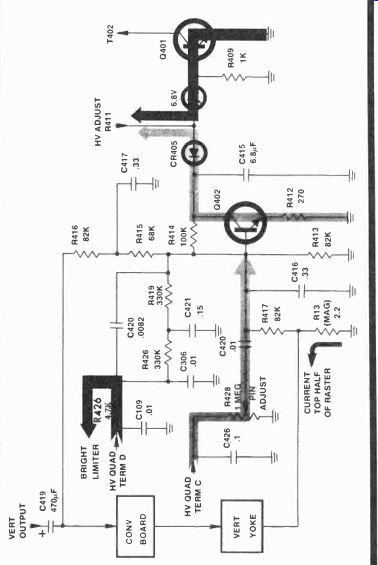
Fig. 10-10. RCA solid-state side pincushion amplifier. (Courtesy Carl Moeller)
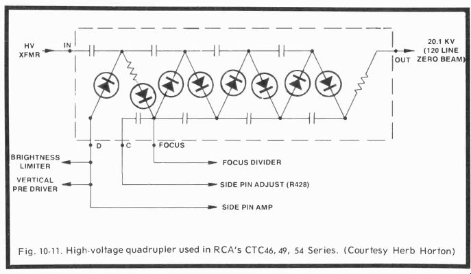
Fig. 10-11. High-voltage quadrupler used in RCA's CTC46, 49, 54 Series. (Courtesy
Herb Horton)
The amount of effect which this sample from the quadrupler will have on the pincushion amplifier may be adjusted with R428. The amplifier has been designed so that when brightness is set for a barely visible raster and R428 is set to minimum (CCW ), there will be no pincushion. Then, R428 is adjusted to correct the pincushioning which will appear when the brightness is increased to maximum.
Unlike conventional high-voltage power supplies which rectify a positive pulse from the flyback transformer with a half-wave rectifier, the CTC49 uses a solid-state quadrupler to produce high voltage. This reduces the required pulse amplitude from about 23KV to nominally 6KV. The quadrupler itself is hermetically sealed and is not repairable; however, its schematic is shown in Fig. 10-11 as a means of identifying its external connections.
QUESTIONS
1. What movement is now afoot regarding various power supplies?
2. Why do manufacturers use a large bleeder resistor after the HV output?
3. What's the most important function of the horizontal stage?
4. Do the plate and grid of the horizontal output begin conduction at the same time?
5. Varying the high voltage varies the boost voltage in the same or opposite directions?
6. When the brightness control turns on the output luminance amplifier harder, what happens to CRT beam current?
7. What happens to the high voltage when there is increased beam current? Is this the reason for brightness limiters?
8. With no picture on the screen and adequate high voltage, what do you suppose could be the next logical problem?
9. Name the newest power output drive scheme.
10. A vacuum tube type pincushion transformer, RCA type, corrects for both curvature and beam corrections.
11. What's so important to remember about a pincushion transformer?
12. In Fig. 10-4, use the equation:
E in x R 333 E-o R329 + R 333 and solve for R333, if Eo is 10v, E_in is 200v and R329 is 1 megohm. Try another value for good measure.
13. If R333 was 1K and you wanted an output of 12 volts, what would have to be your input potential?
14. Brightness limiters do what?
15. Vertical sawtooth current through the core of a pin cushion transformer produces a At scan, the permeability will vary from low on each end to high in the center and vary the horizontal deflection current.
16. What happened to the damper in RCA's newest solid state receivers?
17. Why did RCA have to go to an active pincushion circuit in its CTC49 chassis?
Next: Link | --Low-Voltage Power Supplies
Also see:
TV Antennas and Transmission lines
Air Time--An Intro to Television Broadcasting
TV and Radio Tube Troubles (1958)