Probably no subject is more overlooked than antennas and transmission lines. Now, with cable TV bringing good-to-excellent pictures into many homes and more just around the corner, it's time everyone paid more attention to what's coming from the broadcast stations.
TRANSMISSION LINES
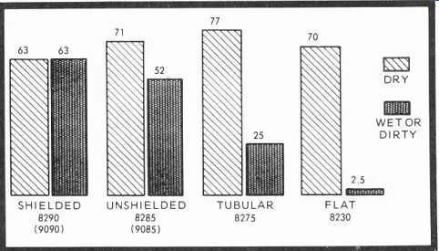
Fig. 13-1. Percentage of signal delivered to the set with clean, dry transmission
line and wet, dirty cable.
Fig. 13-1 shows the percentage of signal remaining on new, clean lines, then on wet, dirty lines, using Belden statistics as an example. The best is also the least as you will observe in the flat twinlead chart showing 78 percent signal reception with new, dry lead, but only 1.5 percent useful signal with old, wet, and dirty lead. And think how much of this inexpensive ribbon is laying on rooftops, taped to masts, looped over gutters (which are parallel to the incoming signal polarity) or stuck to metal conduits and air-conditioning ducts in hundreds of thousands of homes through America.
Good transmission line, like anything else, usually costs money. However, many homeowners will happily pay the extra price if you explain the difference. Here's how. Belden, for instance, recommends the usual ribbon or flat lead for indoor use only, B&W VHF and FM reception only. The older tubular twinlead is all right for B&W VHF and-or perhaps local UHF reception. Coaxial cable is good for master antenna systems such as hotels, motels, apartment buildings, etc., but you'll find it lossy and somewhat capacitive over long distances. Belden recommends 8285 or 9085 (71 percent reception when dry and 52 percent wet and dirty) for all-channel systems in both color and B&W. The same cable also is excellent in fringe areas where there is little interference and only small amounts of soot, salt spray, or heavy smog. At the top of the list, though slightly signal restrictive, is Belden's shielded 8290 (9090) twinlead, especially developed for installations with signal problems such as auto ignition noise, transient pickup and excessive ghosts. Shielded lead-in may be taped to masts, routed through conduits and over metal objects. Best of all, no standoffs or lossy matching trans formers are required, since the nominal impedance approaches 300 ohms. There is no signal current flow in the shield, and both 8290 (9090) and 8285 (same cable without the shield) or 9085 are specifically designed for color television.
The difference between the Belden 8290 and 9090 and the 8285 and 9085 series is that the newer "90" group is smaller in diameter than the older type, more flexible and easier to in stall. However, it has a slightly higher velocity of propagation characteristic and, in the case of 9085, 0.3 pf more capacitance per foot, plus somewhat more attenuation per 100 feet when the 9090 and the 8290 are compared. Also, the wire size (AWG 26) in the 9090 is smaller than the 8290 lead-in, which is listed as 22 AWG. Probably only under very extreme or unusual conditions could you possibly notice a difference in color or B&W reception.
In Fig. 13-2, we can see the percentage of signal remaining or db loss per hundred feet, which shows what happens to signals in the VHF and UHF ranges where lead-in has become brittle, dirty, wet, and thoroughly contaminated. The left vertical column is marked off in percentages, while the adjacent db figures are in parentheses. Observe that with increased frequency (VHF to UHF) the overall loss for all types of cable increases dramatically under unfavorable conditions.
From this chart it is obvious that you must have 10 db or better UHF antennas where either distance or weak signals are reception factors. And a further very reasonable suggestion is ...
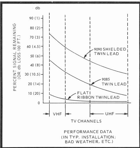
Fig. 13-2. Percentage and db losses for transmission lines when contaminated
or wet.
...that you inspect each antenna installation at least generally when servicing any receiver that indicates weak or ghosty reception. Further, the old conical or V-type antenna that did a half-way job for black and white may just kill color reception on one or more channels and produce multiple headaches unless your initial problem is recognized.
Now, you might ask, "Why is one transmission line better than another?" In any transmission line there are voltages and currents (Fig. 13-3), both coming and going, that can be calculated as the sum of the incident (outgoing) wave and the reflected (incoming) wave. If the line is an open stub, the voltage at the reflecting end is maximum and the current minimum. But if the line is shorted, the current is maximum and the voltage minimum, again at the end furtherest from the signal source. Voltage or current along any transmission line can have maximum and minimum amplitudes and the standing wave ratios (SWR), can be expressed as the ratio of either the E_max divided by E_min voltages or Imax divided by I_min currents. However, IF a transmission line is terminated in an impedance that matches the impedance of the line itself (characteristic impedance), there will be no standing wave ratio and the line will deliver as much signal as it can without interference or undue loss. At this point, the load impedance equals the characteristic impedance, and the power-factor angle of the line is zero, making it virtually a pure resistive impedance. Obviously, the closer a 300-ohm line matches a 300-ohm antenna and a 300-ohm tuner, the more signal can be delivered to any terminating load.
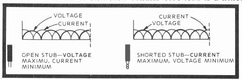
Fig. 13-3. Voltage and current on open and closed transmission lines.
Between any two wires that are close together, there exists an electric field. Naturally, there is also capacitance, and a small leakage current that flows between the two wires, usually expressed as 1 divided by R equals G. This quantity is known as conductance and is calculated in 10-12 ohms per foot. Transmission lines also have properties of resistance, inductance and capacitance, and these are called distributed constants since they appear over the entire length of the line.
When voltage drives current in a transmission line, fields or lines of force encircle the conductors. Around one conductor is a current field (Fig. 13-4) that flows in the opposite direction to the current field set up in the other conductor, while across the insulator separating the wires is a large electric field that exerts a force on any electric charge, which could be an electron or ion. The lines of force in the electric field all move in similar directions, forward at the bottom, reverse at the top. This is illustrated by the flat lead-in drawing in Fig. 13-4.
Since both fields normally operate together, they are collectively known as the lead-in's electromagnetic field.

Fig. 13-4. Electromagnetic fields surrounding three types of lead-in cable.
Observe that the encapsulated dielectric contains almost the complete field,
substantially reducing skin losses.
Now, take a hard look at Fig. 13-4. The drawing on the left represents the flat lead that, when wet and dirty, passes only 1.5 percent signal. Notice that the electro-magnetic field completely surrounds the insulator and is subject to all weather and external elements. Cellular core lead is a little better, but some of the EM field still encircles the outside of the cable. The encapsulated lead-in, however, contains virtually all of the surrounding electro-magnetic field, has proper spacing between conductors, and should be almost impervious to all but the severest weather because of its oval, thick jacket made of a special dielectric that is an element-resistive material. If this encapsulated lead were shielded, it would contain the entire electromagnetic field and, although attenuating the incoming signal slightly, the normal ghosting and noise pickup of ordinary unshielded cable would be eliminated. Obviously, good lead-in does make an enormous difference. And don't forget to give all unshielded lead one turn per foot when connecting it to insulating standoffs, since it will help reduce the SWR. Shielded lead comes straight down, but its ground wire must be grounded.
ROOFTOP ANTENNA
Installing a "price" antenna is probably the surest way to deceive a customer and earn for yourself a lousy reputation.
Jobber salesmen must sell their "lines" to earn a living, but it doesn't mean you should always buy. Inspect the merchandise in advance, ask questions, and request every bit of in formation available on the antenna. Above all, don't buy in a hurry, or because someone says "it's good." There are such things as factual data, including gain and lobe patterns and wind resistance guarantees. Further, different antennas by the same manufacturer have all sorts of varied applications, and a study of the characteristics could save you considerable money, plus invite an excellent reputation. And this does not apply solely to those engaged in full-time antenna installations, because often the problem of poor color or ghosty pictures is directly connected to what is perched on the roof.
Solid knowledge here is very often invaluable.
For all you know, some new recommended antenna may be flimsy or strong, have little or enormous wind resistance, be adequate on low-band channels and literally worthless on high channels, pick up corrosion in 48 hours, have an appalling 1:1 front-to-back ratio, be the most unsightly kluge on the block, and have all the wrong characteristics for the right neighborhood. We didn't mention characteristic impedance, standing wave ratio, UHF characteristics-if it has any-the number of directors and reflectors, or db gain.
Of course, there can be an element of reactive surprise in any installation because all factors just can't be positively pre determined. But a good, careful start usually means a happy ending. Theory says that an antenna is resonant when its measured length is half the wavelength of an incoming signal.
So cutting a simple dipole for a specific frequency is not difficult. But making one antenna right for frequencies from 54 to 216 MHz and, sometimes, all the way to 890 MHz, takes a bit of doing. And everybody is not wholly successful, especially with the UHF-VHF antenna combinations, because it's a hard thing to do. The big antennas have many forward directors, often rear reflectors, and narrow beam-widths. Small antennas have wide beam-widths, few reflectors, but often side and back lobes.
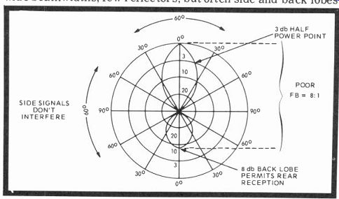
Fig. 13-5. Polar pattern diagram with front and back lobes indicating good
directivity, but a poor front-to-back ratio (F B) of 8db. (It should be at
least 15 db or better.) Side lobes are nonexistent, but this antenna would
pick up many signals from the back and be highly directional.
Therefore, if stations were not in line, you would have to use a rotor, that will certainly pickup stray and surrounding signals-and these can mean leading or trailing ghosts in the picture. So your only protection is to learn to read the gain and lobe patterns that every manufacturer should furnish with an antenna. In this way, you at least have a fighting chance for a reasonable installation at a reasonable cost, along with a satisfied customer.
INSTALLATIONS
Before considering the technical aspects of an installation, a list of DO and DON'T rules should help those unfamiliar with the basics of the task.
DO
1. Buy substantial mounting brackets and, if possible, stainless steel straps (banding) for long-lasting installations.
They cost more, but stay put.
2. Use coated steel masts instead of aluminum masts for strength, especially in regions where high winds are prevalent.
3. Masts approaching 10 feet tall or taller should be guyed for added strength wherever possible. Five-foot masts usually carry almost any antenna if the mounting brackets are sturdy. Do BOLT together connecting sections.
4. Consider weather protected antennas and masts over those which are uncoated. Weather, salt spray, smog, corrosion, and dust can more easily contaminate those that aren't.
5. Check the antenna gain and lobe patterns first before buying any antenna. A quick analysis of the installation area, coupled with front-to-back ratios, SWR, and pattern lobes can save many a tough situation that could plague both you and the customer for months and possibly years. Even then, a narrow band antenna won't produce the broad response of a log periodic. So go LP if there are many stations to be received.
6. Where stations are located in diagonal or quadrature directions (90 degrees apart), a rotor is needed unless your signal bounce factor is superb. Otherwise, choose an antenna with a low front-to-back ratio if you want stations from the rear.
7. When using VHF-UHF combination antennas at distances over 20 or so miles from the transmitter, check the signal coming in directly from the antenna-on the roof if possible with a portable TV-before making the final installation. Sometimes you'll find the lead-in and especially any non-amplifying two or four-set couplers-will cause considerable problems with UHF.
8. If you're checking an antenna on the roof with a television receiver, tilt, raise, and lower the unit for maximum gain and orient (turn) for best reception. Any peculiarities that show up in the final installation, then, will be due to the lead-in "dress," line loss, or proximity to metal conductors. In difficult situations, try different areas on the rooftop. One-man installations, with a portable TV for a helper, often can out perform a two-man job since a single individual necessarily has to be more careful.
9. In using most coaxial cable, don't forget the 72- to 300 ohm matching transformers and leave a small slit or drain hole in the plastic covering where it enters the house to let water out. A waterlogged piece of coax can induce all sorts of problems.
10. You can easily put two antennas on the same chimney (Fig. 13-6) if you allow enough vertical distance, say, 4 to 6 feet, to prevent inter-antenna interference.
DON'T
1. Parallel gutters, AC current lines, air-conditioning ducts, or other metal structures with unshielded twinlead; the ghosts you'll attract will all be nightmares.
2. Put cheap installations in difficult areas where there are reflections, poor signal-to-noise ratios, or great distances.
Be fair with the customer as well as yourself ; it's better to lose a lousy job than suffer perpetual aggravation.
3. Hurry to buy either antennas or transmission lines without knowing their specifications. "That which is cheap is often dear" in terms of personal reputation and customer satisfaction. Usually, the best is none too good.
4. Succumb to the habit of blaming the television set for your installation troubles until you've at least tried an indoor antenna to see if there's improvement in reception. Traps and attenuators can remove a great deal of interference most receivers can't reject.
5. Expect the new "mini" antennas to solve all your general reception problems. One day, such antennas may be high-gain, low-profile, and omnidirectional, but not yet. In any area with reflections, weak signal strength, and directional needs, a good standard antenna will be needed for a long time to come.
6. Put up a big antenna in high wind areas without considering its strength characteristics. If wind velocities reach 100 mph, a 75-mile-an-hour antenna installation can conceivably snap or bend at the mast, and you can't bend it back into position without mending (probably welding) the break.
7. Tape twin or oval lead-or any unshielded lead in-to masts, standoffs, gutters, or metal of any description unless you want ghosts induced by standing waves in the received pictures. Further, never lay any transmission line on a roof.
The consequence is signal absorption (loss) and rainwater damage, leading to added reception problems. Use standoffs in all installations at all times, and never allow the lead-in to touch metal.
8. Neglect the use of standoffs even with shielded lead-in, since they keep the lines taut. A loose lead-in sways in the wind and could eventually break the copper stranding as well as crack the plastic shield.
9. Tell a customer the old B&W installation is always good for color. It often is, especially if there is unusually good, ghost-free reception. But take no chances when secondary signals retard images you see as ghosts, and where weak signals show a bit of snow. Ten to one, he'll need a good, new installation, complete with the usual accessories.
10. Be bashful about quoting a reasonable price. Others get it, why not you?
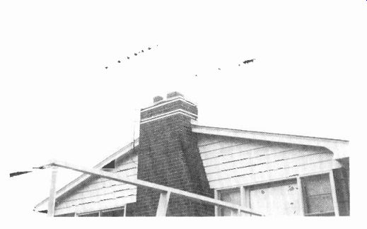
Fig. 13-6. JFD and RCA antennas mounted on the author's chimney, one above
another. The upper antenna ( RCA) supplies two outlets, while the larger (JFD)
delivers good signals to four. No power is used, and 11 Washington-Baltimore
stations are received, most of them very well.
WORKING RESISTIVE DIVIDERS
While keyed AGC (with average video AGC combined with keyed AGC on the way) has dealt the routine divider a near mortal blow, there are still instances where standing wave ratio (SWR) line and antenna feedback voltages and currents, along with poorly devised and selected antennas, make resistive dividers quite attractive as inexpensive receiver-to-transmission line matches and signal attenuators. Obviously, such items can be bought in nice, packaged plastic cases, but that takes all the fun out of any do-it-yourself enterprise along with an impressive demonstration of skill you can exhibit before some attentive customer. With cable TV on the increase, it may be that you'll be using such devices more than you know.
For practical purposes, there are four kinds of resistive pads: L, T, pi, and H configurations, and there are certain specific things you can do with each of them and other things you cannot.
An L pad, for instance, is good for matching impedances of various descriptions with a minimum loss. It can be devised in two versions: balanced and unbalanced. Both types are shown in Fig. 13-8. The unbalanced unit can be used with coaxial cable (the shield is grounded), while the balanced divider is good for balanced transmission lines such as 300-ohm twinlead, for instance. Equations for RI and R2 are given in the drawing for both types, with R2 over 2 substituted for R2 in the balanced version. Therefore, if you wanted to match a 72-ohm unbalanced coax to a 300-ohm receiver input:
R2 = ( Zou t /Z_in -1) x R1
Let RI equal 82 ohms.
So:
R2 = 246 ohms
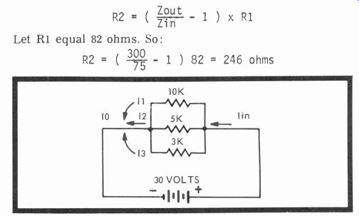
Fig. 13-7. Series-parallel to series current conversions.
Fig. 13-8. Useful L pads in both balanced and unbalanced versions for matching different impedances with lowest loss.
...or 240 ohms for round figures. If you are interested in matching a 200-ohm tuner to a 300-ohm antenna (and this could happen either way), the balanced equation is:
[…]
So each R2 is 87 ohms-in a balanced pad, of course. And this should be a good introduction to balanced and unbalanced L pads.
You can have lots of combinations, and you can produce a pretty good match with non-phase shifting carbon film or composition resistors, Tolerances are not too critical.
Remember, however, these L pads are for matching different impedances and are called asymmetrical networks since the input and output impedances are not equal. Now, if you were matching an unbalanced asymmetrical network, say from 50 to 300 ohms, R1 would be 56 ohms and R2, 270 ohms, while in a balanced asymmetrical network R1 would be the same 56-ohm value, but R2 would be halved and amount to approximately 120 or 140 ohms.
T and H pads (Fig. 13-9) are similar to the L pads, in that the T pads are unbalanced while the H pads are balanced.
However, these two (as opposed to the L pads) are asymmetrical since they are signal attenuators situated between matched impedances and do nothing but absorb some of the voltage and current between antenna and receiver. Handling the equations for these two networks is just a bit more tricky than the L pads, since you're using a signal attenuation ratio in voltage rather than simply a straight resistive calculation.
When you're talking about a 10 or 20 db loss, you'll usually have to go to a slide rule or a table of db current and voltage ratio loss figures and dig them out. We'll provide you with some of the more common ones in case these tables aren't readily available:
A 10 db loss is a current-voltage loss ratio of 0.316.
A 20 db loss is a current-voltage loss ratio of 0.100.
A 25 db loss is a current-voltage loss ratio of 0.056.
A 30 db loss is a current-voltage loss ratio of 0.032.
Voltage-current in decibels is 20 log 1 E2 over E1.
As an example, let's calculate R1 and R2 for a typical T pad that must attenuate the incoming signal by 10 db:
R1 = Zo
A Now, since the T pad is a symmetrical unbalanced network, we'll be using it either with 50- or 75-ohm impedances where the shield side of the cable is common ground. Let's select 75 ohms.
R1-75 ( N1166 71-1 ) ( °:17 ) 75 = 75 (0.519) = 39 ohms
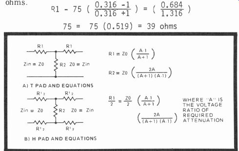
Fig. 13-9. Signal attenuating T and H pads where input and output impedances
match. T pad (A) and equations; H pad ( B) and equations.
R2 = Zo 2A 2 x 0.316 (A+1) (A-1) (0.316 + 1) (0.316-1) =75(2.6-64)-52.7 ohms
So a 10 db pad has for its T network values, R1, 39 ohms, and R2, 52.7 ohms.
The nearest commercial values would be about 33 and 51 ohms. Now, how about a 20 db padder for the H network where the input and output impedances are typically 300 ohms? This, of course, is a balanced symmetrical network and is useful in attenuating signals coming down the usual 300-ohm TV transmission line. Here's how this one is done, since you can see that a 20 db voltage-current loss amounts to a ratio of 0.100.
R2 = Zo ( 2A )-2(0.1) (A+1) (A-1) (1 + 0.1) (1-0.1) 300(0.2) 60 R2-60.6 ohms-, T1.1 x 0.9) 79-9 300 R1 Zo 2(0.100-1) 2 2(A-1) (A+1)-0.100 +1)
150 (0.9)-150 (.817) = 122.6 ohms (1.1) 300
And here you can juggle the values slightly so that R1 comes out to about 120 ohms and R2 expands to 68 ohms for typical commercial values. However, all R1s must be the same value.
From these examples you should be able to calculate virtually any attenuation needed in any of these T and H pads.
There are also pi padder networks that can be used readily in place of T padders if you wish. The converting equations are rather easily used. This time, however, we'll adopt the term impedance instead of resistance and so make the application broader in the sense that not only will it cover resistances but reactances as well. Therefore, the symbols in Fig. 13-10 will be in impedance ( Z) terminology for both the T and pi section padders. To convert from a pi to a T network, use the following equalities:
Z1-
ZaZb Z2-
Za + Zb + Zc Z3-
ZaZc Za + Zb + Zc Za + Zb + Zc ZbZc
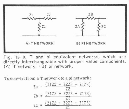
Fig. 13-10. T and pi equivalent networks, which are directly interchangeable
with proper value components.
(A) T network; (B) pi network.
To convert from a T network to a pi network:
Za Zb-
Zc-
(Z1Z2 + Z2Z3 + Z1Z3) Z2 (Z1Z2 + Z2Z3 + Z1Z3) Z3 (Z1Z2 + Z2Z3 + Z1Z3) Z1
INTERFERENCE, GHOSTS, AND SUCKOUTS
Useful quarter-wave and half-wave elimination filters can be made from ordinary twin-leads. In recent years, such filters have not been needed, generally, with the more expensive B&W U.S. type receivers, since front-end filters and trapping effects have been highly effective against CB, commercial, and other forms of high- and low-band interference. With the less expensive sets, though, you may find an occasional in stance where a simple trap will make the difference between artistic success and technical failure. Especially did we find this true recently in an apartment installation where the house amplifier wasn't the best and the installation of a simple trap restored lots of gratifying color. Had the coax been a twinlead line, we might have used a piece of metal foil or our thumb and forefingers to find a point of signal suckout due to poor line-receiver termination. At that juncture we could have installed a small 2- to 20-pf ceramic trimmer across the line and tuned it with a plastic or fiber wand for best signal strength. Or, we could have left the metal piece in place, secured with good, sticky tape.
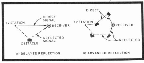
Fig. 13-11. These drawings show how trailing and leading secondary images
(ghosts) are formed by single and multiple reflections. (A) delayed reflection;
(B) advanced reflection.
Ghosts (Fig. 13-11) can be a nuisance and sometimes very difficult to deal with. There are the usual trailing ghosts to the right of the main image where the prime signal travels a shorter distance than the reflected information and the ghost is delayed by a microseconds interval and appears after the usual picture information. You may also have a leading ghost on the left of the initial image when the receiver is quite close to a TV transmitter. This is due to either internal signal pickup, a very long transmission line from receiver to antenna and perhaps parallel to the signal polarity, or some sort of tuner trouble that used to crop up more frequently than it does now because of overheated vacuum tube load resistors when there were tube short circuits. Then there are even multiple ghosts or vertical banding troubles due, again, to tuner problems, several reflected images, or open or wrong value capacitors in the horizontal windings of the deflection yoke.
With today's "hot" front ends (transistorized), you'll find antenna and lead-in problems much more prevalent than internal receiver faults. Therefore, in poor signal neighborhoods where ghosts abound, try a highly directional antenna, perhaps with rotor, and a fully shielded twinlead line.
Reduce as many external possibilities as you can, then experiment further with antenna-receiver line matching.
Fig. 13-12. How to tell difference frequency of interfering signals in multiples of vertical and horizontal sync rates. Notice that we said "difference" frequencies and not fundamentals. The interfering frequencies is 5 X 39.94 Hz. (A) At (B) the interfering frequency is 157.34 kHz.
In an exceptionally tough situation, it can pay you to actually calculate, even in a somewhat rough fashion, the actual distance the reflected signal is bouncing from the offending building or tower toward the set. You simply do it this way: measure in inches the width of the picture, and be sure it is not unduly over-scanned; then measure the distance between some identical point in the ghost and the original picture for a ratio of, say, 1.5 inches to 20 inches; then, knowing that television signals travel about 1,000 feet per microsecond in the air and that the receiver's CRT beam is swept through one horizontal line in 52.4 microseconds, the total horizontal sweep time amounts to 52,400 feet-microseconds, or about 10 miles.
Therefore, in this instance 1.5 divided by 20 x 52,400 equals about 3930 feet, the air distance the reflecting image travels not necessarily the actual distance between the receiver and the reflecting object. For instance, a building half the distance of 3930 feet behind the receiver could be the culprit just as easily as one at a 45-degree forward angle from the receiver.
However, should there be an out-standing tall object at some known point within the approximate distance, it could well be your target. If you want to locate the direction of the ghost accurately, you can probably find it with a field strength meter and a receiver with an antenna you can move. At some particular channel frequency you will find a strong signal, then one that is not so strong; the latter should be your quarry.
Occasionally, you will have to determine if a secondary image, such as a ghost, is originating in the transmission line or is simply an air-path signal such as we calculated. You can do this by estimating the length of line, say 100 feet, multiplying it by 2 and dividing by some constant between 0 and 1, usually 0.83. If the ghost has an air-path of a thousand feet or more, the transmission line is not at fault since 100 x 2 divided by 0.83 equals 200 divided by 0.83 equals 240 feet. And, of course, the airpath of the transmission line is probably less than one fourth of a thousand or more feet.
One peculiarity you can always calculate with ballpark accuracy is the gross frequency of overriding interfering signals (Fig. 13-12). If they are horizontal, count the number of dark lines and multiply by 59.94 Hz, since this is the vertical repetition rate, and you will have the difference frequency of the interference. Or, if the lines are either diagonal or vertical, count them and multiply by the horizontal rate of 15,734 Hz. If there are too many black slant bars to count, total the number of lines in an inch, then multiply again by 15,734 kHz for a final figure.
This all sounds very easy and good, but there's just one small catch-you've been calculating the difference and not the fundamental frequency. These vertical and horizontal lines are, in truth, fundamentals which, unfortunately, you seldom find in real life. Usually, interference is the sum and difference signals between the interfering frequency and the video carrier if the TVI is 4 MHz or less. If more than 4 MHz, they are the difference signals only. So an accurate determination of a very high frequency is rather tricky. About the best way to discover your trouble is to get some sort of listing of transmitters in the immediate area, take a signal generator along and try to match those frequencies so you can arrive at the fundamental. Otherwise, you may have an aimless hunt trying to establish the interfering problem since these stray energies seldom lie still and allow you to establish a solid "fix" on their specific characteristics.
If you have an old or very cheap receiver, the addition of a high-pass filter at the tuner input terminals may help.
However, all the newer receivers, especially the quality in; so an additional series filter would not be very beneficial, unless the interference is extremely marginal, and then only because the filter supplies an extension of what was already there.
The second point about filters is this: in 300-ohm input receivers there is already a 300- to 75-ohm transformer (called a balun) at the antenna input to the tuner. If you can imagine a 150-ohm transmission line of infinite length with the input in series to "see" 300 ohms and the output in parallel to "see" 75 ohms, you would have immediate attenuation from DC to about 5 MHz anyway, because one side of the output is already connected to ground. Naturally, the line isn't infinite, so you put in a ferrite that makes the balun look like this theoretical line and the tuner input "see" its proper impedance.
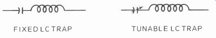
Fig. 13-13. Fixed and tunable LC traps can be used to shunt aside an unwanted
frequency. A 20- to 100-pf capacitor is usually used for C.
The shielded 75-ohm input, however, goes directly into the usual high-pass filter between the RF amplifier and the antenna. This high-pass filter often has 80 db rejection (60 db at any rate) for the receiver's IF return characteristics, and does pretty much the same for any incoming frequencies at and below 54 MHz as well. In some of the top receivers, there is also a tunable FM notch rejection filter to help with interference from the 88-108 MHz FM-stereo band. So, really, regardless of what the "old hands" are saying about the addition of multi high-pass filters, you're probably going to have to be pretty specific with any strong interfering frequency, since it may just be overriding the input traps and any additional high-pass filter installed also.
Before leaving this topic there are two more points we should make: Normally, the interfering frequency will have to be within 500 kHz of either the chroma energy or picture carrier if you are to see a low power interfering signal. The second point is that a 75-ohm input is quite useful on a "cold" chassis since it can be grounded. On a "hot" chassis, you can't take such a ground to the antenna input terminals.
In future CATV receivers, there will be better limited passband tuners, greater shielding, and more attention paid to the video IFs where interference can be picked up also as we discussed. Reputedly, most of the forthcoming crop will double in brass-be good for air signals as well as cable.
TRAPS
Traps are used when low-pass and high-pass filters are ineffective. This condition often occurs when the receiver is in the midst of a strong RF signal area. Image frequency (the local oscillator signal plus or minus the IF; the opposite of the IF) interference may respond either to a fixed or tunable trap (Fig. 13-13). It may be reduced or eliminated by 300-ohm or 72-ohm open-ended stubs Fig. 13-14, depending on the impedance of the transmission line. You can try the easy way. Use a pair of cutters and begin chopping at the tail end of about 35 inches of line until the stub is tuned to the desired frequency, or you can use an equation that will drop you directly into the ballpark.
The length of a quarter-wave, open-ended trap for 300 ohms can be found by using the following equation: Length (in inches) equals 2450 divided by the frequency in MHz. For a 72-ohm open-ended stub, you can use a slightly different constant: Length (in inches) equals 1945 divided by the frequency in MHz. However, you must use two equal length pieces, one for each antenna terminal, and the shields must be joined at several points and grounded to the chassis. Both types of traps are attached to the receiver's antenna terminals, along with the lead-in. The length for a disturbing frequency of 100 MHz is: 300-ohm length equals 2450 divided by 100 MHz, or 24.5 feet.
In addition to quarter-wave stubs, there are also half-wave stubs. Over the years we have found half-wave stubs easier to use, since fewer reflections or ghosts are usually induced with this type of shorted stub. The difference between quarter-wave and half-wave traps is basically the terminations. In the first, the voltage is maximum at the open end while the current is minimum. In the second, the current is maximum and the voltage minimum at the point of termination. The equations are also somewhat different. To calculate a half-wave 300-ohm stub: Length equals 4,850 divided by the frequency in MHz. For a half-wave 72-ohm stub: Length equals 3,900 divided by the frequency in MHz.
You must, however, recall one very important point: A quarter-wave stub also attenuates second harmonics, while a half-wave stub attenuates third harmonics, in addition, of course, to the fundamental. So a 90-MHz signal attenuated by a quarter-wave trap would also give you problems on Channel 8, between 180 and 186 MHz. A half-wave stub would attenuate frequencies at 270 MHz also, if cut to the same 90 MHz fundamental. So when using traps, be careful you don't interfere with a signal, and do check all receiver channels before put ting the job to bed.
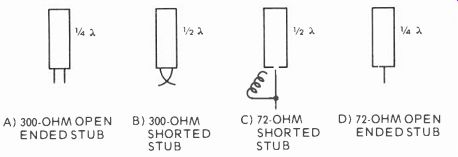
Fig. 13-14. Different types of stubs may be used to bypass and reject interfering
frequencies. (A) 300-ohm open ended stub; (B) 300-ohm shorted stub; (C) 75-ohm
shorted stub (D) 75-ohm open ended stub.
QUESTIONS
1. When you use ordinary flat twinlead in dirty, foul weather, what percentage of signal do you expect it to pass?
2. What cable should you use in ghosty and noisy areas?
3. As frequencies increase, do cable transmissions become better?
4. What's a good practice before servicing any receiver with an outside antenna?
5. Why is one transmission line superior to another?
6. When do you decide on an antenna for any installation?
7. A narrow front pattern lobe is good for directivity. A good front-to-back ratio is often desirable. Is there a long distance antenna with a broad beamwidth and no side lobes?
8. Can you mount two antennas on the same chimney?
9. Why bolt together 5-ft mast sections?
10. Why install stainless steel chimney straps?
11. Can you lay ordinary twinlead on a roof? Why not?
12. Where do you find leading edge and trailing edge ghosts?
13. In ghosty neighborhoods, what do you do?
14. 75-ohm inputs in the new receivers often have a high pass filter input with a to db rejection for IF reflections.
Next: Link | --Troubleshooting
Also see:
TV Antennas and Transmission lines
Air Time--An Intro to Television Broadcasting
TV and Radio Tube Troubles (1958)