All television receivers have sync separators, most have AGC, but many do not have noise gates. The principle of the sync separator (Fig. 7-1) is simply to strip the video from the composite waveform and amplify sync pulses above the black level. Out of this action is derived the serrated vertical integrated (slowly and successively charging capacitive) pulses that time the vertical oscillator when it is not freewheeling or "fly-wheeling." These charging pulses come from the trans mitted six vertical pulses that are surrounded by horizontal and equalizing pulses, but the relatively long duration of the vertical pulses allows the integrator to charge in steps, while filtering the shorter pulses to AC ground. The horizontal pulses, of course, appear during each line scan at the 52.4-microsecond rate, while the repetition rate of the vertical pulses transmitted during field times is 31,500 per second or inversely in time at about 32 microseconds. All horizontal, equalizing, and vertical pulses are completed in a single field of 1.4 milliseconds, half the frame rate of 30 complete pictures per second.
Horizontal pulses are merely RC differentiated to potentially sharpen the leading edge and filter out vertical frequencies. They become rather sharp rectangular pulses and provide precision timing for the horizontal oscillator.
You can well imagine what happens when vertical pulses find their way into the horizontal sweep circuits, or horizontal pulses into the vertical sweep. Here is a pointed instance where a recurrent sweep oscilloscope is utterly useless, since there is no calibrated time base to determine the interfering frequency.
There's really not much more to a sync separator.
Usually, it's a single-stage tube or transistor circuit that is biased sufficiently to clip the video, and the dual outputs (vertical and horizontal sync) are sent on the way. When troubleshooting vertical or horizontal circuits, it is a good idea (if you have a dual-trace oscilloscope) to hang one probe on the output of the sync separator and work through the defective sync circuit with the second vertical input. This way you can tell if there's any frequency deviation and always have a ready reference in case something peculiar turns up, such as the vertical or horizontal starting up all by itself. It's happened! AGC is something else. The whole principle began with simple diode rectification of video which produced a DC feedback to the IF and RF amplifiers. Naturally, this has changed radically since the 1950s, and there are a number of systems in use today, most of them what is called keyed AGC.
Very simply put, a keyed system operates only during the horizontal retrace time and then only on the tips of the horizontal sync pulses. Although every keyed AGC amplifier is lightly biased by some DC voltage, pulses from the flyback transformer are usually rectified by a diode to supply the operating voltage for the keyer. As horizontal sync pulses are received, the flyback transformer keys the AGC stage on, resulting in an output. The larger the amplitude of the in coming sync pulses, the greater the keyed AGC output, and the more controlling effect it has on the receiver's IF and RF amplifiers. In this way, tuner and video IF stage conduction is easily managed and the system offers not only marked resistance to airplane flutter but also gives some protection against noise pulses. Possibly in the future, AGC systems will combine keyed operation and a system based on an average AC video. The two would complement one another where each is individually least effective.
Noise gates are not always included in the less expensive receivers, and sometimes you're inclined to wonder if they really work or if they're just there for nuisance value.
However, were it not for noise circuits, there'd be considerably more interference appearing on color television screens than there already is. Unfortunately, noise circuits can produce some rather tough troubles that seem to defy rapid detection.
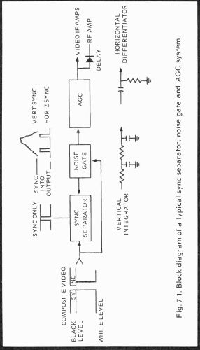
Fig. 7-1. Block diagram of a typical sync separator, noise gate and AGC system.
Originally, noise stages (or circuits) were put in receivers to black out sync and perhaps video ( this is what we're driving at when we show a noise gate going to the AGC in Fig. 7-1) when overriding noise pulses were present. Probably many people think this is still completely true, but it isn't. Just like the rest of today's more advanced television receivers, noise circuits are now definitely associated with AGC, and hardly with sync at all. In one of the newest sets, noise controls the AGC shift from one strength signal input to another so that RF amplifier conduction is increased or decreased for minimum noise and to prevent mixer crosstalk (RCA, if you're curious).
So, in this instance, there's little talk about sync, but much more interest in detecting increases in AGC action that affect a receiver front end and cause viewing problems that can be prevented by selected settings of the noise circuit.
By the way, although we're told to look at a noisy station and set noise controls for the least color snow, we have found that an oscilloscope reading the composite video signals before chroma takeoff can also show you where and when to stop tuning the noise potentiometer. It's at the point where you have a full amplitude video waveform and no sync compression. The author, by the way, uses the composite video signal on a strong station to set the AGC in all receivers if they have the usual DC control. Some CRT sync bends are hard to see. The oscilloscope is precise.
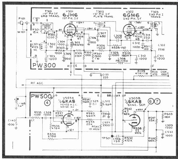
Fig. 7-2. Schematic of the vacuum tube keyed AGC, noise and sync circuits
used in RCA receivers.
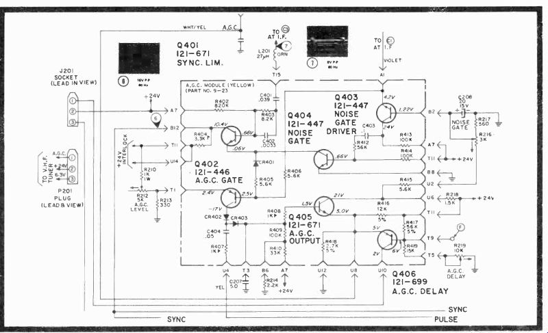
Fig. 7-3. Schematic of Zenith's 4B15C19 sync-AGC-noise module.
TUBE-TYPE AGC, NOISE, & SYNC SYSTEMS
At first glance, these are puzzling circuits (Fig. 7-2), but basics still apply. An LC series circuit resonant at 376 kHz from the grid of the first video amplifier supplies positive sync pulses at a horizontal rate to the grid (pin 6) of the keyed AGC and noise inverter. Sync information included in the full video signal arrives at the screen grid (pin 8) through R533 and continues on to the sync separator through C526 and R532.
Over regular variations in the amplitude of incoming video, the screen and control grids ride together and produce more negative voltage at the plate of V503A for larger incoming video.
Keying from the flyback (with filtering) is applied to the plate circuit of V503A, where the tube is also biased from the resistive string on PW300 through terminal E. If a large spike of noise appears, the grid and suppressor work hard, the positive-going noise spike is inverted and this drives the AGC amplifier into non-conduction, cutting off the picture and possibly also the sync, although the screen grid of the keyed AGC tube would have to be driven heavily for that. It probably depends on the size of the disturbing spike. The AGC set control determines the bias of both cathodes of the keyed AGC tube and sync separator.
The AGC IF negative control voltage finds it way to V301 through R302 and the grid circuit, again going into the board through terminal E. The RF AGC delay is accomplished by R540 and C530, with a charge delay of 5.6 milliseconds, and the usual drop through a 560K resistor.
The sync separator bias comes through terminal D on PW300. The bias is probably slightly affected by the AGC action of V503A. Plate voltage is only 73 volts with respect to cathode, so there's not too much swing. Also, there's a 22-meg resistor between plate and grid for added bias control. The capacitors and resistors aid the grid-plate action of V503B, which strips the horizontal and vertical sync information from the overall video signal. Relatively pure horizontal and vertical sync pulses appear at the plate of the separator. The grid is fed through terminal BB, C527, C526, and R532. Bias on the grid of V503B also should be fairly high since R538 and R542 act as a grid bias voltage divider; R538 is connected to a potential of 105 volts. We would suspect bias to measure around 30 volts, since the grid normally has to be slightly more negative than the cathode for satisfactory tube operation.
V503B produces a single output and separate vertical and horizontal sync pulses are derived by low-pass (integrator) and high-pass (differentiator) filters.
SOLID-STATE SYNC, NOISE, & AGC SYSTEMS
In the Zenith Duramodule (Fig. 7-3), negative horizontal sync pulse spikes are applied to the module at Al and the emitter of the noise gate driver, through R406 to the base of AGC gate Q402, driving this transistor into conduction which is proportional to the amplitude of the sync pulses. Pulses from the flyback transformer key CR402 on, supplying the collector operating potential for the AGC gate. CR403 rectifies the positive portion of the gate output and C207 filters out any AC so that the base of Q405 now sees a more positive DC in addition to the forward bias already applied from the +24-volt line.
The AGC output stage has a certain amount of applied collector voltage also from the 24-volt line, which also supplies Q405's emitter with constant voltage and, at the same time, furnishes operating voltage for both the emitter and base of Q406 through R416 and divider R417 and R419. The AGC delay control completes the current path to ground and firmly divides the voltage drop at the base of Q406. In turn, the AGC level set controls the voltage and, consequently, the conduction point for the emitter of Q402, the AGC gate.
With AGC gate Q402 operating, a positive voltage turns on AGC output Q405 and its emitter rises above 5 volts. When this occurs, a positive AGC voltage is transferred to the IFs for forward, current-limiting bias. At 6.7 volts, transistor Q406 now begins to conduct, affecting the RF amplifier after the more than one volt delay, since the Q406 emitter must be 0.7 volt more positive than the base for Q406 to conduct.
The sync separator, meanwhile, takes positive video from terminal T15 through capacitors C401 and C402. Normally conducting diode CR401 is back biased by each negative in coming horizontal sync pulse tip. Video coming through C401 sets up a relatively negative voltage on the base of Q401 so that only the tops of the incoming positive sync tips overcome the bias and cause the sync limiter to conduct and pass sync in formation to the collector. During times of no signal input, CR401 supplies part of Q401's emitter bias.
Noise gate and driver have a bias set control that obviously can affect both sync and AGC since the conduction point of Q402 will consume negative sync pulses, and the action of the Q404 noise gate will upset the sync limiter bias and produce distortion. In such circuits, beware of hasty adjustments.
Noise gate control R216 is set so that the noise gate driver is back biased and will not conduct on normal signals.
However, if a large negative transient appears at the emitter of Q403, the transistor will be forward biased and conduct, sending a signal through C403 and R412. This voltage is not inverted and so turns off the noise gate itself. Transistor Q404 then stops conducting, opening the emitter of Q401 so that it cuts off the sync limiter for the duration of the transient.
Therefore, little or no AGC and no sync are generated during the nanosecond or microsecond interruption. In other words, you're missing only part of a line anyway, and the eye is normally too slow to follow any such transistory occurrence.
SYLVANIA'S SPECIAL AGC CIRCUIT
In the D12 Gibralta chassis (Fig. 7-4), collector supply voltages for the AGC gate are rectified pulses from the flyback transformer. Negative-going video from the first video amplifier drives Q304 into conduction during reception of horizontal sync pulse tips. The point of conduction depends on the setting of AGC control R352 at the bottom of the diagram.
This control is bypassed by C308 to avoid amplifier degeneration.
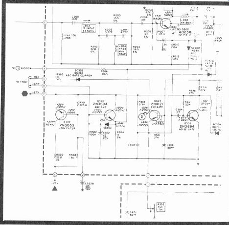
Fig. 7-4. Sylvania's special AGC, IF and RF control circuits. (Courtesy Joe
Thomas)
With no incoming video, the base of Q304 rises to 2.75 volts to limit AGC action. As sync tips arrive in varying amplitudes, Q304 conducts more or less and delivers pulses of proportional amplitudes back through SC302, across the D-B windings of the flyback transformer, and then to the base of AGC amplifier Q300. The large R302-C302 RC filter supplies a time constant of 1.5 seconds, sufficient to remove AC and permit only a varying positive DC drive for the unity gain emitter follower AGC amplifier.
At maximum gain, Q304 develops no positive bias, so the AGC amplifier does not conduct. But first IF stage Q200 is now constant at about 4 volts, while the emitter of the IF draws about 3 milliamperes through AGC threshold diode SC200 and AGC amplifier emitter resistor R304. This current sets a level of some 3 volts at the emitter of AGC amplifier Q300 and establishes a bias for the base of the AGC-controlled RF amplifier in the tuner.
With increasing signal input, the AGC gate develops a positive voltage and draws more emitter current through R304. This, in turn, reduces the current through IF amplifier Q200, and lessens the gain in the reverse AGC mode. At the same time, the voltage across R304 is constant; therefore, biasing the RF amplifier into maximum gain. With further increases of AGC voltage, current through the AGC amplifier increases and current ceases through Q200, so diode SC200 opens. Series resistors R210 and R212 become active and provide current control for the Q200 emitter with SC200 open and limit the maximum AGC gain reduction in the IF range, specifically determined for the best noise versus mixer overload. Further AGC increases will develop additional voltage across R304, delivering more forward bias to the RF amplifier.
SEMICONDUCTOR AGC DESIGN CONSIDERATIONS
The following discussion is based on material originated by Karol Siwko in Batavia, in which he analyzes IF response problems in semiconductor receivers and especially those coincident with automatic gain control.
Pole shifting (changing the IF response with gain) has been the usual design goal in vacuum tube receivers, where changing the input impedance altered the gm in a pentode.
When transistors arrived, IF amplitude, phase response, stability, and gain had to be further dealt with, plus predictable AGC performance. Bipolar small-signal transistor gain can be controlled through output and input resistance by forward AGC, regenerative feedback, and also external damping diodes for frequency and circuit Q response.
Curves showing strong signal and weak signal responses are drawn in Fig. 7-5A for video IFs and at the intercarrier sound detector, Fig. 7-5B. The solid curve in each case demonstrates conventional response for strong signal reception, while the dashed curve is the signal response modified for weak signal reception.
When faint signals are being received, the picture carrier is shifted to the peak of the response curve for the following advantages:
1. With the signal rise time reduced, the overall noise is down and, with most picture content in the lower frequencies, the bandwidth reduction attenuates the high-frequency noise. Also, only low energy in the picture is reduced, and this produces an improved signal-to-noise ratio.
2. Maximum gain appears at the best fine tuning point, and this extends the range of the automatic frequency control, while all traps maintain their design functions.
3. The chroma carrier is moved further down on the response curve relative to the video carrier, producing less chroma output through the color level circuits, which also attenuates color noise during weak signals.
Also on feeble input signals, the sound intercarrier level is raised proportionally with that of the video carrier to maintain the sound limiting sensitivity, plus keep the center frequency amplitude response down so that the video sideband and intermodulation noise in the sound channel can be reduced.
A good quality TV IF amplifier should use at least five poles in the bandpass for sufficient compromise among ...
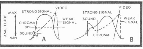
Fig. 7-5. The sound and video I F response characteristics rise ideally
and proportionately with a shift from strong to weak incoming signals. Video
rises in proportion to sound on a weak input at the video IF curve (A). Sound
IF detector response ( B) showing the sound and video rising and peaking on
very weak signals. (Courtesy Karol Siwko)
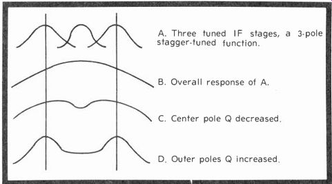
Fig. 7-6. Three poles in stagger-tuned stages, and what happens when they
are combined or the Q is reduced or increased. A 3-pole stagger-tuned function,
showing three tuned IF stages (A). The overall response of A is demonstrated
by curve B. Center pole Q decreased (C), and the outer pole Q increased (D).
... bandwidth, group delay, and response skirt selectivity. Fig. 7 6 illustrates a 3-pole function in its various stages, made up of three single-tuned circuits to produce the overall response illustrated in Fig. 7-6B. The curves at Fig. 7-6A represent three single-tuned circuits, such as a stagger-tuned IF system, with sound and video carriers at the top of each outside peak. The center pole Q is decreased at Fig. 7-6C and this causes the center dip, while the Q is increased among the outer poles at Fig. 7-6D, so the curve response expands at these points.
Siwko then proceeds to illustrate video IF changes in gain by varying the input impedance of a common-base transistor (Fig. 7-7). He tells graphically, how the transistor beta changes relatively little with variations of emitter current, and that the emitter-to-base resistance increases almost linearly with rises in emitter current. So, he deduces, in the reverse bias operating range of this common-base transistor, its gm varies just about linearly with the emitter current. In an actual circuit, with a beta spread exceeding 4:1, the gm stays within 20 percent. The equation for gm is given by the simplified equality:
A (gain) Z (load)
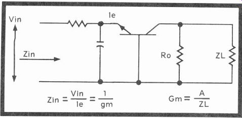
Fig. 7-7. Very simplified drawing of a common-base transistor IF stage. Gain
is controlled by changing the input impedance.
He calculates the difference in useful gain between the common-base and common-emitter configurations to be 13 db.
In summary, Siwko remarks that the pole-shifting IF is relatively easy to design and suitable for mass production, with special importance attached to its use in integrated circuits. Obviously, such a stage or stages can easily be controlled by a well-designed AGC circuit, and probably will be, as developments continue in this very competitive consumer products race for bigger shares in the color television market. And automatic peak video gain under weak signal conditions, with the plus factor of noise reduction to boot, seems to make this type of IF-AGC approach quite attractive. This is another advanced circuit you will want to remember.
QUESTIONS
1. Vertical and horizontal sync pulses have but one purpose. What is it?
2. What was the original AGC detector and how is AGC operated today?
3. What are the usual plate characteristics of a sync separator?
4. Can the noise-gate adjust in Zenith's AGC-sync module affect AGC?
5. What's the usual noise pulse duration in any receiver?
6. Noise pulses last milliseconds or microseconds and usually affect how many scanning lines?
7. What is the significance of the IF curves in Fig. 7-5?
Next: Link | --Vertical Deflection System
Also see:
TV Antennas and Transmission lines
Air Time--An Intro to Television Broadcasting
TV and Radio Tube Troubles (1958)