Digital electronics
The beginning of electronics was radio technology, and it is useful to remember that the first applications of radio to the transmission of messages used Morse code . A signal was (and still is) transmitted in Morse by switching the radio transmitter (in the early days, nothing much more than a spark-coil connected to an aerial and an earth) on and off, with the on time being either short (dot) or long (dash) . This is a form of digital signal, because the essence of a digital signal is that it consists of two states only, on and off, with nothing in between having any significance. We would nowadays classify Morse as a digital pulse duration modulation, since the off time has no meaning, and the length of the on time determines either a dot or a dash being signaled, Figure 1.1. Morse code totally dominated radio until the development of transmitting valves in the 1920s, at which time it became possible to modulate radio frequencies with audio waveforms.
Even with the simplicity of Morse, problems can arise. Customarily, the dash has a duration of three times that of the dot, but ...

Figure 1.1 Morse was the first type of digital code. The significant part
of the wave is the high (or 1) part, and the duration of this is used in a
two-sense code.
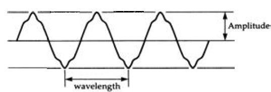
Figure 1.2 A typical audio waveform, simplified. A real audio waveform is
always more complex, and never a sinewave.
... when Morse is sent and received by human operators there can sometimes be confusion over long dots and short dashes. Even if the Morse is transmitted and read by machines, the effects of integration and other signal distortion can make it difficult at times to distinguish between dot and dash signals.
Recall at this point what we mean by an audio waveform, as might be represented by the graph of Figure 1.2. This shows a waveform, meaning that the pattern shape will repeat for several cycles, in which the voltage varies continually over the time of the cycle. A waveform like this will be, assuming that the system is a good one, a copy in electrical voltage terms of a sound-wave that was picked up by a microphone and which might be recorded or broadcast directly. The important point here is that the shape and frequency of the electrical wave is identical to the shape and frequency of the sound wave and the shape and frequency of the sound wave in turn is entirely responsible for the type of sound that we hear . The amplitude of the electrical wave, in volts, is proportional to the amplitude of the sound wave (in terms of air pressure), and is related to the loudness of the sound. The frequency of the electrical wave is the same as the frequency of the sound wave, and is responsible for our sensation of pitch. In short, the electrical wave is, or ought to be, a completely faithful copy of the sound wave and carries all the information of that wave.
This, in turn, is the start of all the problems that beset linear analog recording systems. The sound wave is a complicated wave whose origins are often as mysterious as its psychological effect on us. We cannot, for example, make violins that will reproduce the sound of the Stradivarius violins despite all our modern technology, and no amount of experimenting with woods and varnishes has ever proved to provide this elusive sound. It is hardly surprising that the complexity of the sound from a full orchestra defies any straightforward analysis, and we have to add to all this complication the impact that the sound-waves make on our own ears . The ear itself is a most remarkable receiving instrument, and these that have escaped the attentions of the disco, the personal stereo and the ghetto-blaster are capable of detecting sound levels that are un-measurably low and are yet capable of responding to subtle changes that theory tells us should be impossible to detect . The wonder is that any form of recording system could cope, and yet the history of recording is filled with witnesses saying that the sound is of wonderful quality (from the first horn gramophone) or of unparalleled fidelity (first electrical recording) . In the early days, it was a wonder that it was done at all, and if the singing sounded anything like Galli-Curci in full sail, it seemed to be a miracle. A generation later, ears were sharper and senses more critical, and the noticeable improvements soon became the standards by which to judge further developments . It has been so for each step in the improvement of recorded sound, from the flat wax disc to the LP record. Each time, we have been sure that perfection is within grasp, and within a few years we have become aware that it is not. Much of the problem lies in the recording medium itself. Consider what we are trying to achieve in cutting a master disc. A disc cutter is a mechanical cutting tool, a miniature chisel, that has to move in a pattern that exactly copies the change of voltage in the waveform so that it will cut a groove of that same shape in a disc. The sound-wave encounters no problems of this type -- all it has to do is to move your ear-drum, which is a considerably lighter device, and with no requirement to cut grooves in your skull. No mechanical device can easily be vibrated in the pattern of a sound wave, and it is hardly surprising that the cutters of recording lathes require enormous amplifier power in order to achieve results - 500 to 1000 watts are the kind of figures we are talking about for each channel . The original discs have then to be copied by moulding methods, adding yet another source of distortion. Finally, the copied recording is played by lowering a stylus into the groove, spinning the disc and expecting the shape of the groove to vibrate the stylus in exactly the pattern of the groove shape. This would be difficult enough if only the lightweight stylus had to be moved, but the stylus has to be connected to some form of electrical transducer, the pickup, and this in turn means that movement is not so easy, and perfect reproduction of the waveform is that much more difficult . You might imagine that magnetic tape recording offered a solution, and to some extent it can for studio work. The problem ...
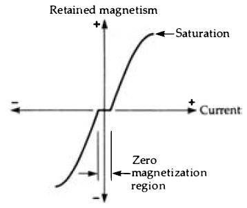
Figure 1.3 A typical tape magnetization characteristic. Most of the shape
is curved, and there is a region in which small magnetizing signals leave
no trace at all on the tape.
... of all magnetic recording, however, is that the whole process is inherently non-linear. If you plot the intensity of retained magnetism for a magnetic material against the current through a coil that causes the magnetization, you arrive at a severely curved graph shape (Figure 1.3) which is not even continuous. For very small amounts of coil current, the tape is not magnetized at all, and for large amounts of current the tape saturates, meaning that it becomes magnetized so that the range of amplitudes that can be recorded is severely limited. The range of frequencies that can be recorded is limited by the combination of tape speed and recording head gap. In addition, the recorded tape has a noticeable noise level that can be heard clearly during passages of soft music and is very obtrusive when narrow strips of tape are used. All of these problems can, of course, be attacked by using ultrasonic bias, wide tapes, high tape speeds and volume compression, and tape mastering is used extensively, though only too often for the purpose of doctoring recordings rather than for reasons of fidelity.
Even the transistor, almost universally used for amplification, is by no means a linear device, and the history of hi-fi is virtually the history of circuit techniques that have been devised to get around the inherent non-linearity of, at first, valves and subsequently transistors and ICs. We appear to find a new cause of distortion about each ten years and take about ten years to find a palliative, so that the audio scene has never been static, and recording engineers have been known to wonder if some critics would be satisfied with the original sound, let alone a recording. In general, though, electrical distortions are easier to deal with than mechanical distortions, and the weakest links in any sound reproducing system have been recognized as the recording process itself and the loudspeaker. The use of digital methods is the first step in a fresh look at the whole system, a complete rethink of the recording process . Digital signals A digital signal is one in which a change of voltage, and the time at which it occurs, are of more importance than the precise size of the change . Nothing is conveyed by the shape of a digital waveform, nor even by its precise amplitude . All of the waveforms in digital circuits are steep-sided, pulses or square waves, and it is the change of voltage at either side of the pulse that is significant.
For that reason, the voltages of digital signals are not referred to directly, only as 1 and 0 values. The important feature of a digital signal is that each change is between just two voltage levels, typically 0V and +5V, and that these levels need not be precise . In this example, the '1' level can be anything from 2.4V to 5.2V, and the '0' level anything from 0V to 0.8V. By using 0 and 1 in place of the actual voltages, we make it clear that digital electronics is about numbers, not waveforms or amplitudes . In digital circuits, the pulses will be used to make or break connections, using circuits called gates, or they will be counted. In neither case is the shape of the pulse important other than in the requirement that the change of voltage between the levels must be as fast as possible . In neither case is the amplitude of the pulses important provided that each pulse is between some voltage that is acceptable as a 0 level and another voltage that will be acceptable as a 1 level . The importance of using just two digits, 0 and 1, is that this is ideally suited to electronic devices and also to tape recording. A transistor, whether bipolar or FET, can be switched fully on or fully off by a suitable voltage at its input (base or gate), and these two states can be ensured easily, much more easily than any other states because no form of bias is needed. By using just these two states, then, we can avoid the kind of errors that would arise if we tried to make a transistor operate with, say, ten levels of voltage between the two extreme voltage levels of cut-off and saturation.
By using only two levels, the possibility of mistakes is made very much less . There are, for example, no problems about bias since the only requirement is that the device shall be biased either fully on or fully off. There are no problems about linearity, because nothing is being amplified, the output signal from a digital circuit will normally be of the same amplitude as the input signal . The only snag is that any counting that we do has to be in terms of
Place No. 0 1 2 3 4 5 6 7 8 9 10 11 12 De nary 1 2 4 8 16 32 64 128 256 512 1024 2048 4096
Place No. 13 14 15 De nary 8192 16384 32768
To convert a binary number into denary, find the denary figure for the place number of each 1, then add the denary numbers. Remember that the place numbers are counted from the right hand side, starting with zero.
For example, the number 10010110 contains a 1 in positions 1, 2, 4 and 7. These place numbers correspond to 2, 4, 16 and 128 respectively, so that the denary equivalent is 150. Figure 1.4 A table of powers of two, and how the table can be used in converting from 8-4-2-1 binary code into denary numbers.
Denary to binary conversion is done on paper by dividing the denary number by 2, noting the remainder, and then repeating the process on the result of division until the final remainder (which is always 1) is obtained. The binary number consists of the remainder digits read from the bottom up.
Example: Convert the number 583 to binary.
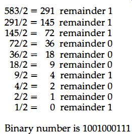
Figure 1.5 How denary numbers can be converted to binary on paper.
... only two digits, 0 and 1. For some applications, this is of no importance because counting may not be involved. If you use a digital circuit, for example, to control two gas valves, then the outputs of the digital circuit will turn each valve either fully on or fully off. The action is one of control only, not of counting. On the other hand, we might want to turn one valve on after two pulses at an input, and the other valve on after four pulses at the same input, and this action is quite definitely one of counting.
Counting with only two digits means using a scale of two. There are many types of scales that can be used, as we shall see later;- but the most important one is the 8-4-2-1 scale. There's nothing particularly difficult about this, because numbers in this scale, often called simply the binary scale, are written in the same way as ordinary numbers (denary numbers or scale-of-ten numbers) . As with denary numbers, the position of a digit in a number is important. For example, the denary number 362 means three hundreds, six tens and two units . The positions represent powers of 10, with the right hand position (or least-significant position) for units, the next for tens, the next for hundreds (ten squared), then thousands (ten cubed) and so on. For a scale of two, the same scheme is followed. In this case, however, the positions are for units, twos, fours (two squared), eights (two cubed) and so on.
The table Figure 1.4 shows powers of two and how a binary number can be converted into denary form. Figure 1.5 shows the conversion in the opposite direction. The maximum number that can be expressed in a scale of two depends, as it does in any numbering system, on how many digits are used. If we allowed only two binary digits (or bits) then we would be counting with a number range of 0 to 3 only. By using 8 digits (called one byte), we can cope with numbers from 0 to 255, and by using sixteen bits (called one word) we can make use of a number range from 0 to 65535. The number of bits that can be used is therefore an important feature of any-digital system that involves counting, and this is something that we shall return to later.
Digital circuits are switching circuits, and the important feature is fast switching between the two possible voltage levels. Most digital circuits would require a huge number of transistors to construct in discrete form, so that digital circuits make use of ICs almost exclusively. These I Cs can make use of either bipolar transistors in integrated form, or of MOSFETs, and both types are extensively used. MOSFET types are used extensively in computing as memory circuits and in the form of microprocessors . The bipolar types are used where higher operating speeds and larger currents are required, and these applications occur both in computer circuits and in industrial controllers . The digital ICs that are used in digital audio circuits are almost invariably purpose designed ICs rather than the types of over-the-counter chips that would be used in other types of digital circuitry.
As it happens, the development of digital ICs has had a longer history than that for analog devices. When ICs could first be produced, the manufacturing of analog devices was extremely difficult because of the difficulty of-ensuring correct bias and the problems of power dissipation. Digital IC circuits, using transistors that were either fully off or fully on, presented no bias problems and had much lower dissipations. In addition, circuits were soon developed that reduced dissipation still further by eliminating the need for resistors on the chip. Digital ICs therefore had a head start as far as design and production was concerned, and because they were immediately put into use, the development of new versions was proceeding before analog ICs made any sort of impact on the market.
Given, then, the advantages of digital signals as far as the use of transistors is concerned, what are the wider advantages for the recording of signals? The most obvious advantage relates to tape or any other magnetic recording. Instead of expecting the magnetization of the tape to reproduce the voltage of a signal, the tape magnetization will be either maximum in one direction or maximum in the other . This is a technique called 'saturation recording' for which the characteristics of most magnetic recording materials are ideally suited. The precise amount of magnetization is no longer important, only its direction. This, incidentally, makes it possible to design recording and replay heads rather differently so that a greater number of signals can be packed into a given length of track on the tape. Since the precise amount of magnetization is not important, linearity problems disappear.
Tape noise consists of signals that are far too small to register, so that they have no effect at ail-ore digitally recorded signals.
This also makes tapes easier to copy, because there is no degradation of the signals caused by copying noise, as there always is when conventional analog recorded tapes are copied.
Since linearity and noise are the two main problems of any tape (or other magnetic) recording system it is hardly surprising that major recording studios have rushed to change over to digital tape mastering. The surprising thing is that it has been so late in arriving on the domestic scene, because the technology has been around for long enough, as long as that of videotape recording. The advantages that apply to digital recording with tape apply even more forcefully to discs. The accepted standard method of placing a digital signal on to a flat plastic disc is to record each digit bit as a tiny dimple on the otherwise flat surface of the disc, and interpret a digital 1 as the change of reflection of a laser beam.
Once again, the exact size of the dimple is unimportant as long as it can be read by the beam, and only the number of dimples is used to carry signals . We shall see later that the process is by no means so simple as this would indicate, and the CD is a much more complicated and elaborate system than the tape system (DAT) . The basic principles, however, are simple enough, and they make the system immune from the problems of the LP disc. There is no mechanical cutter, because the dimples have been produced by a laser beam which has no mass to shift and is simply switched on and off by the digital signals. At the replay end of the process, another (lower-power) laser beam will read the pattern of dimples and once again this is a process which does not require any mechanical movement of a stylus or any pickup mechanism, and no contact with the disc itself.
As with magnetic systems, there is no problem of linearity, because it is only the number of dimples rather than their shape and size that counts. Noise exists only in the form of a miscount of the dimples, and as we shall see there are methods that can reduce this to a negligible amount . Copying of a disc is not so easy as the moulding process for LPs, and mass production requires enormous capital investment and costly inspection processes, all of which are threatened by the advent of digital tape systems . A CD copy, however, is much less easily damaged than its LP counterpart, and even discs that look as if they had been used to patch the Ml will play with no noticeable effects on the quality of the sound - though such a disc will sometimes skip a track. The relative immunity to wear is a very strong point, because this allows CDs to recoup their high costs when they are used in jukebox applications or for the inescapable deluge of recorded sound in restaurants and other public places. This has also allowed CD libraries to flourish, because each disc can earn its keep in loan fees and can afterwards be sold at a good price because it can still be played with no noticeable deterioration in quality.
Numbers for one cycle (8 samples)
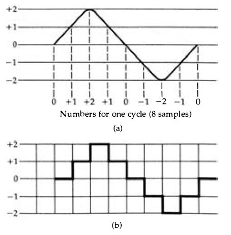
Figure 1.6 (a) Coding an analog signal into five levels (zero is counted
as one level), so that each part can be represented as an integer number (no
fractions) . The replay (b) of this wave shows the block shape due to the
five level quantization.
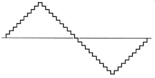
Figure 1.7 The result of a quantization with a much larger number of levels.
The waveshape in this example is triangular because this makes it easier to
show the effect of the quantization.
Paying the price
No advantages are ever obtained without paying some sort of price, and the price to be paid for the advantages of digital recording and reproduction consists of the problems of converting between analog and digital signal systems, and the increased rate of processing of data . To start with, the sound wave is not a digital signal, so that its electrical counterpart must be converted into digital form. This must be done at some stage where the electrical signal is of reasonable amplitude, several volts, so that any noise that is caused will be negligible in comparison to the signal amplitude. That in itself is no great problem, but the nature of the conversion is . What we have to do is to represent each part of the wave by a number whose value is proportional to the voltage of the waveform at that point. This involves us right away into the two main problems of digital systems, resolution and response time . To see just how much of a problem this is, imagine a system that used numbers -2 to +2 only, used on a signal of 4V total peak-to-peak amplitude . If this were used to code a sinewave as in Figure 1.6(a) then since no half-digits can exist, any level between -0.5V and +0.5V would be coded as 0, any signal between +0.5V and + 1.5V as 1 and so on, using ordinary denary numbers rather than binary numbers to make the principle clearer. In other words, each part of the wave is represented by an integer (whole) number between -2 and + 2, and if we plotted these numbers on the same graph scale then the result would look as in Figure 1.6(b). This is a 'block' shape of wave, but recognizably a wave which if heavily smoothed would be something like the original one . We could say that this is a five-level quantization of the wave, meaning that the infinite number of voltage levels of the original wave have been reduced to just five separate levels. This is a very crude quantization, and the shape of a wave that has been quantized to a larger number of levels is shown in Figure 1.7. The larger the number of levels, the closer the wave comes to its original pattern, though we are cheating in a sense by using a sinewave as an illustration, since this is the simplest type of wave to convert in each direction.
Nevertheless, it is clear that the greater the number of levels that can be expressed as different numbers then the better is the fidelity of the sample.
In case you feel that all this is a gross distortion of a wave, consider what happens when an audio wave of 10 kHz is transmitted by radio, using a carrier wave of 500kHz . One audio wave will occupy the time of 50 radio waves, which means in effect that the shape of the audio wave is represented by the amplitudes of the peaks of 50 radio waves, a 50 level quantization. You might also like to consider what sort of quantization is involved when an analog tape system uses a bias frequency of only 110 kHz, as many do. The idea of carrying an audio wave by making use of samples is not in any way new, and is inherent in amplitude modulation radio systems which were considered reasonably good for many years. It is equally inherent in frequency modulation, and it is only the use of a fairly large amount of frequency change (the peak deviation) that avoids this type of quantization becoming too crude. Of all the quantized ways of carrying an audio signal, in fact, FM is probably the most satisfactory, and FM methods are often adopted for digital recording, using one frequency to represent a 0 and another to represent a 1.
This brings us to the second problem, however. Because the conversion of an audio wave into a set of digits involves sampling the voltage of the wave at a large number of intervals, the digital signal consists of a large set of numbers . Suppose that the highest frequency of audio signal is sampled four times per cycle. This would mean that the highest audio frequency of 20kHz would require a sampling rate of 80 kHz . This is not exactly an easy frequency to record even if it were in the form of a sinewave, and the whole point of digital waveforms is that they are not sinewaves but steep-sided pulses which are considerably more difficult to record. From this alone, it's not difficult to see that digital recording must involve rather more than analog recording.
The next point is the form of the numbers . We have seen already that numbers are used in binary form in order to allow for the use of only the two values of 0 and 1. The binary code that has been illustrated in this section is called 8-4-2-1 binary, because the position of a digit represents the powers of two that follow this type of sequence. There are, however, other ways of representing numbers in terms of 0 and 1, and codes such as the Gray code (Figure 1.8) and the Excess-3 code are used for some commercial processes. The advantage of the 8-4-2-1 system is that both coding and decoding are relatively simple. Whatever method is used, however, we cannot get away from the size of a binary number. It is generally agreed that modern digital audio should use a sixteen-bit number to represent each wave amplitude, so that the wave amplitude can be any of up to 65536 values . For each sample that we take of a wave, then, we have to record 16 digital signals, 0 or 1, and all 16 will be needed in order to reconstitute the original wave.
This is the point on which so many attempts to achieve digital coding of audio have foundered in the past . As so often happens, the problems could be more easily solved using tape methods, because it would be quite feasible to make a sixteen-track tape recorder using wide tape and to use each channel for one particular bit in a number. This is, in fact, the method that can be used for digital mastering where tape size is not a problem, but the disadvantage here is that for original recordings some 16 to 32 separate music tracks will be needed. If each of these were to consist of sixteen digital tracks the recorder would, to put it mildly, be rather overloaded. Since there is no possibility of creating or using a sixteen-track disc, the attractively simple idea of using one track per digital bit has to be put aside. The alternative is serial transmission and recording.
Denary 8-4-2-1 Gray Code
Code
-----------
Gray scale converters use four bits only, because the conversion between four-bit binary allows binary-coded denary (BCD) systems to be used. If true 8-4-2-1 binary is needed, then converters between BCD and 8-4-2-1 can be used also.
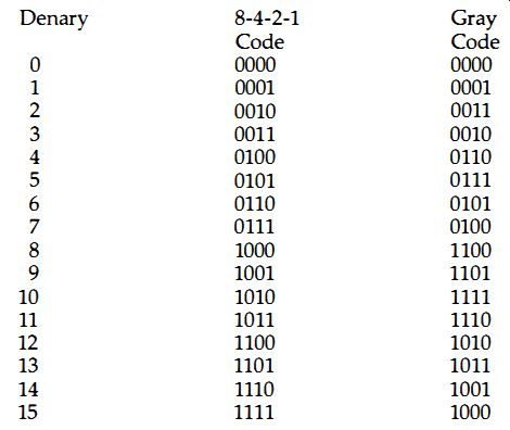
Figure 1.8 The Gray code, which is used in preference to the 8-4-2-1 type
for many industrial control applications. The main advantage is that only
one digit changes at a time as the count progresses . IC converters can be
obtained for four-bit Gray code to or from four-bit binary code.
Serial means one after another. For 16 bits of a binary number, serial transmission means that the bits are transmitted in a stream of sixteen separate signals of 0 or 1, rather in the form of sixteen separate signals on sixteen channels at once. Now if the signals are samples taken at the rate of 60kHz, and each signal requires sixteen bits to be sent out, then the rate of sending digital signals is 16 x 60 kHz, which is 960 kHz, well beyond the rates with which ordinary tape or disc systems can cope. As it happens, we can get away with slower sampling rates, as we shall see, but this doesn't offer much relief because there are further problems . When a parallel system is used, with one channel for each bit, there is no problem of identifying a number, because the bits are present at the same time on the sixteen different channels . When bits are sent one at a time, though, how do you know which bits belong to which number? Can you be sure that a bit is the last bit of one number or is it the first bit of the next number? The point is very important because when the 8-4-2-1 system is used, a 1 as the most important bit means a value of 32768, but a 1 as the least important bit means just 1, Figure 1.9. The difference in terms of signal amplitudes is enormous, which is why codes other than the 8-4-2-1 type are used industrially. The 8-4-2-1 code is used mainly in computing because of the ease with which arithmetical operations can be carried out on numbers that use this code.
Even if we assume that the groups of sixteen bits can be counted out perfectly, what happens if one bit is missed or mistaken? At a frequency of 1 MHz or so it would be hopelessly optimistic to assume that a bit might not be lost or changed. There are tape dropouts and drop-ins to consider, and discs cannot have perfect surfaces. At such a density of data, faults are inevitable, and some methods must be used to ensure that the groups of sixteen bits, called 'words' remain correctly gathered together . Whatever method is used must not compromise the rate at which the numbers are transmitted, however, because this is the sampling rate and it must remain fixed. Fortunately, the problems are not new nor unique to audio; they have existed for a long time and been tackled by the designers of computer systems . A look at how these problems are tackled in simple computer systems gives a few clues as to how the designers of audio digital systems went about their task.
To start with, when computers transmit data serially, the word that is transmitted is not just the group of digits that is used for coding a number. For historic reasons, computers transmit in units of eight bits, called a byte, rather than in I6-bit words, but the principles are equally valid. When a byte is transmitted over a serial link, using what is called asynchronous methods, it is preceded by one 'start bit' and followed by one or two (according to the system that is used) 'stop bits' . Since the use of two stop bits is very common, we'll stick to the example of one start bit, eight number bits and two stop bits . The start bit is a 0 and the stop bits are 1’s, so that each group of eleven bits that are sent will start with a 0 and end with two 1’s. The receiving circuits will place each group of eleven bits into a temporary store and check for these start and stop bits being correct. If they are not, then the digits as they come in are shifted along until the pattern is now correct - the process is shown in outline in Figure 1.10. This means that an incorrect bit will cause loss of data, because it may need several attempts to find that the pattern fits again, but it will not result in every byte that follows being incorrect, as would happen if the start and stop bits were not used.
The use of start and stop bits is one method of checking the accuracy of digital transmissions, and it is remarkably successful, but it is just one of a number of methods. In conjunction with the use of start and stop bits, many computer systems also use what is known as parity, a method of detecting one-bit errors. In a group of eight bits, only seven are normally used to carry data and the eighth is spare. This redundant bit is made to carry a checking signal, which is of a very simple type. We'll illustrate how it works with an example of what is termed even parity. Even parity means that the number of 1’s in a group of eight shall always be even. If the number is odd, then there has been an error in transmission and a computer system may be able to make the transmitting equipment try again. When each byte is sent the number of 1’s is counted. If this number is even, then the redundant bit is left as a 0, but if the number is odd, then the redundant bit is made a I, so that the group of eight now contains an even number of 1’s. At the receiver, all that is normally done is to check for the number of 1’s being even, and no attempt is made to find which bit is at fault if an error is detected. The redundant bit is not used for any purpose other than making the total number even.
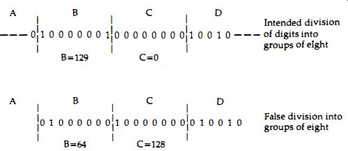
Figure 1.9 An error caused by a missing digit in a serial transmission could
cause each following byte to be wrongly read. Intended division of digits
into; False division into groups of eight
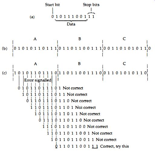
Figure 1.10 (a) Using one start and two stop bits for each group of eight
data bits so as to make synchronization easier for serial systems. (b) The
form of a three byte signal with start and stop bits added . (c) How an error
in the first bit will be discarded. The bits are read in groups of eleven,
shifted by one bit each time. Data is not used until the pattern of a zero,
eight data bits and two 1’s can be found again.
Parity, used in this way, is a very simple system indeed, and if two bits in a byte are in error it is possible that the parity could be correct though the transmitted data was not . In addition, the parity bit itself might be the one that was affected by the error so that the data is signaled as being faulty even though it is perfect . Nevertheless parity, like start bits and stop bits, works remarkably well and allows large masses of computer data to be transmitted over serial lines at reasonably fast rates. What is a reasonably fast rate for a computer is not, however, very brilliant for audio, and even for the less-demanding types of computing purposes, the use of parity is not really good enough, and much better methods have been devised. The rates of sending bits serially for computing purposes range from the abysmally slow 110 bits per second to the rather unreliable 19,600 bits per second. Even this fast rate is very slow by the standards that we have been talking about, so it's obvious that something rather better is needed for audio information. This is something that we shall be looking further into in section 3 and also in subsequent sections . All in all, then, you can see that the advantages that digital coding of audio signals can deliver is not obtained easily, whether we work with tape or with disc. The rate of transmission of data is enormous, as is the bandwidth required, and the error-detecting -- methods must be very much better and work very much faster than those needed for the familiar personal computers that are used to such a large extent today. That the whole business should have been solved so satisfactorily as to permit mass production is satisfying, and even more satisfying is the point that there is just one world-wide CD standard, not the furiously competing systems that have made video recording such a problem for the consumer.