Conversion and modulation
The conversion of analog signals into digital form is the essential first step in any digital recording system. This step is part of the recording process rather than the replay process, but the methods that are used for this conversion affect very considerably how we can recover signals during replay, so that the principles need to be understood. Note, incidentally, that we have to distinguish between conversion and modulation in this context. Conversion means the processing of an analog signal into a set of digital signals, and modulation means the change from the original digital signal into the type of digital signal that is used to convey the data and also how this is impressed on the medium, tape or disc. The two are, however, bound up with each other because many forms of conversion are also forms of modulation, and many are completely unsuitable for a digital recording system. The word 'modulation' is used in rather a confusing way in digital audio reference books, so that you need to be sure which meaning is intended. Consider, for example, the type of modulation that is represented in Figure 3.1. In this system, an analog signal is sampled at intervals to obtain a pulse whose amplitude is equal to the amplitude of the audio signal. This is little more than a digital version of amplitude modulation of a carrier, and it has about as much application to high-fidelity sound . The point is that in this case the conversion and the modulation system are one and the same - you can' t separate them. The more modern methods are all based on a modulation system called pulse code modulation, in which the digital pulses represent the amplitude of the sample ...
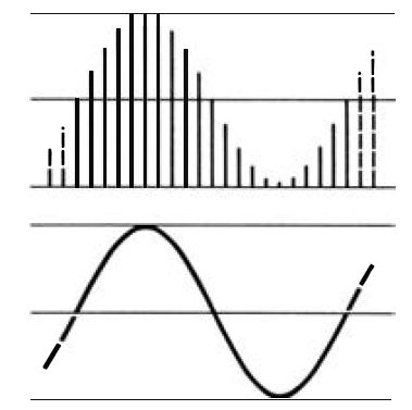
Figure 3.1 Illustrating pulse amplitude conversion and modulation. This system
is of little use because it is as susceptible to interference as AM radio
. Its only merit is simple conversion.
... of analog signal in a coded form, rather than by their amplitude, phase or repetition rate . This leads to the separation between the methods of converting the amplitude of the analog signal into digital signals and the methods of organizing these digital signals into a form that can be recorded, the other modulation part of the problem.
Leaving aside the matter of conversion for the moment, we have to try to see why modulation should be such a problem. The conversion will result in a number in digital form for each sampled piece of analog signal, and this number will be proportional to the amplitude of the signal sample. Now from what we saw in section I, this digital number will be in binary form, using the digits 1 and 0, and it will be possible to have numbers that consist of mainly 1’s and mainly 0’s, such as 1000000000000000 and 011111111 . Now though these numbers cause no problems in the registers of a digital circuit, we have to think about how we could record them. A long string of 1’s or 0’s is to all intents and purposes a steady signal, like a DC level, and neither tape nor disc is a medium that can record DC. Whatever modulation method we choose must therefore be able to break up such patterns in such a way that changes from 0 to 1 or 1 to 0 take place often enough for the tape or disc system to respond correctly. In other words, what we are recording and replaying is the change from 0 to 1 or 1 to 0, and if these changes are too infrequent, there's a strong possibility that things will go wrong. The solution to this lies in the method of modulation of binary signals into a form of code that is less likely to cause such problems . This implies that signal amplitudes will be quantized into binary digits which are then modulated into another (longer) string of 1's and 0' s. Both of these processes take time, and one of the problems inherent in digital audio is to ensure that such processes are carried out as fast as possible . Fortunately, storage of digits allows more time to be allocated for processing.
Conversion
From now on in this section we shall concentrate on A-D conversion, the process of changing an analog signal into a digital number . The first thing to settle is how many bits should be used for a number. As we saw in section 1, the use of eight bits permits us to distinguish 256 different amplitude levels, and this is insufficient for the range of sound amplitude we are aiming for. Putting this into concrete terms, we would want, in order to be considered of the highest audio standard, to be able to cope with a signal amplitude range of 90 db, which corresponds to a signal amplitude range of about 32000 to 1. Using just 256 steps of signal amplitude would make the size of each step about 123 units, too much of a change. This size of step is sometimes referred to as the quantum and the process as quantization. In these terms, then, 256 steps is too coarse a quantization for good quality of sound.
If we move to the use of 16 bits, allowing 32767 steps, we can see that this allows a number of steps that is well matched to the amplitude range of 90 db or 32000:1. This is the quantization that has been used in the CD system therefore, and also in digital tape systems. We would use the smaller number if we could, because working with sixteen bits takes longer when the bits are recorded one by one, and particularly when we use the modulation method that will be described in section 6. It is this choice of coding along with the choice of modulation system that makes the operating frequency of a CD system so very high, equivalent to video frequency signals . Smaller quantization numbers have been used for TV stereo transmissions by compressing the digital signals, and these techniques could be usefully employed on discs or tape if it were possible to convert existing equipment, or if a new format were introduced (as has been done in the audio circuits of the Video-8 recorders). There's more to the choice of number of bits than meets the eye, however . Ideally, the amplitude of a signal at each sample would be proportional to a number in the 16-bit range. Inevitably, this will not be so, and the difference between the actual amplitude and the amplitude that we can encode as a sixteen bit number represents an error, the quantization noise. We don't have to resort to any elaborate mathematical proofs to see that the greater the number of bits we use to encode an amplitude, the lower the quantization noise will be. What is less predictable without theory, however, is the effect on low-amplitude signals . For low-amplitude signals, the amount of quantization noise is virtually proportional to the amplitude of signal, so that to the ear it sounds less like noise, and more like distortion. The greater the number of digital bits you use for encoding, the worse this effect gets unless you do something about it. The cure, by a strange paradox, is to add noise! Adding white noise - noise whose amplitude range is fairly constant over a large frequency range - to very low amplitude signals helps to break the connection between the quantization noise and the signal amplitude and so greatly reduces the effects that sound so like distortion. This added noise is called 'dither' , and is another very important part of the conversion process. The noise level is very low, corresponding to a one-digit number.
Sampling rate
All A-D conversion, however, starts with sampling. Sampling means that the amplitude of the audio analog signal is measured and stored in a short interval of time, and if sampling is to be used as a part of the process of converting from analog to digital signals then it has to be repeated at regular intervals . The principles of the process are illustrated in Figure 3.2, from which you can see that if you intend to convert an analog waveform into digital form with any degree of fidelity, then you need to take a large number of samples in the course of one cycle.

Figure 3.2 A waveform sampled 45 times, indicated by the dotted vertical
lines. At this density of sampling, very fine detail of the waveform can be
captured.

Figure 3.3 Inadequate sampling of the original wave (a) causes the replayed
wave (b) to be block-shaped, and a poor replica. This is less significant
if the amplitude of such portions of a wave are very small, which in practice
they always are.
If you take too few samples, then the digital version of the signal (Figure 3.3) will look quite unlike the analog version. On the other hand, if you take too many samples per cycle, you are working with a lot of redundant information and wasting disc space. Whatever sampling rate you use must be a reasonable compromise between efficiency and fidelity, and as it happens, the theory of sampling is by no means new so that we don't have to look far for our answers . The idea of digital communications has been around for some time now, and in 1948, C. E. Shannon had published his paper 'A mathematical theory of communications' that the whole of digital audio is based around. The essence of Shannon' s work is that if your sampling rate is twice the highest frequency component in an audio signal, then the balance between fidelity and excessive bandwidth is correctly struck. Note that this pivots around the highest frequency component . If you were working with a 1 kHz sinewave, you would not achieve digital conversion of hi-fi standard by using a sampling rate of 2kHz, unless your reverse conversion was arranged always to provide a sinewave output.
What Shannon's theory is about is non-sine waves, the sort of waves we are working with in audio, which can be analyzed into a fundamental frequency and a set of harmonics . What this boils down to is that if we look at a typical audio waveshape (Figure 3.4), then the highest frequency component is responsible for a small part of the waveform, whose shape looks nothing like a sinewave and which could equally well be represented by a sawtooth. Purists will object that this is not a true representation of the effect of harmonics, but it's one that provides a good mental picture . Sampling the highest harmonic, then, at twice the frequency of that harmonic will provide a good digital representation of the overall shape of the complete wave, all other things being equal .
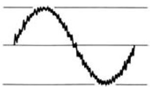
Figure 3.4 A representative audio waveform.
Sampling will give a satisfactory version of this because the approximations affect only the smallest amplitudes of high-frequency signals, portions which many analog systems filter out in any case . Sampling under these conditions provides a set of pulses whose amplitude is proportional to the amplitude of the wave at each sampled point. If we use a spectrum analyzer to see what frequencies are present in such sampled signals we find something like the illustration of Figure 3.5. This consists of the range of frequencies that were present in the analog signal (the fundamentals) plus a set of harmonics centered around the sampling frequency and its harmonics. This is not a problem when the pulse amplitudes are being converted into digital form, but when the pulses are recovered, a filter is needed to separate out the wanted part, which is the lowest range of frequencies, the frequencies of the original signal . The nature of this problem and its solution will be dealt with in section 4.
The existence of these harmonics makes it important to ensure that the sampling rate is high enough. Suppose, for example, that we wanted to work with audio with an 18 kHz bandwidth and we picked a sampling rate of 30 kHz . The harmonics around this 30 kHz sampling frequency would extend down to 30 - 18 = 12 kHz
Audio signal spectrum
Spectrum around sampling frequency (modulation by audio)
Sampling frequency Spectrum around second harmonic of sampling frequency
Frequency
Second harmonic of sampling frequency (other harmonics not shown)
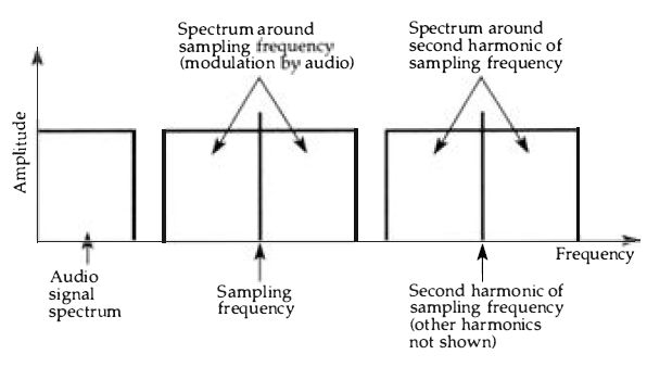
Figure 3.5 The spectrum (plot of amplitude against frequency) for a sampled
waveform shows the frequencies of the original audio signal, plus the sampling
frequency and sidebands (as wide as the audio signal) and a set of harmonics
of the sampling frequency and corresponding sidebands.
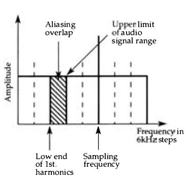
Figure 3.6 Aliasing - the result of using a sampling frequency that is too
low. The upper frequencies of the audio signal overlap the lower frequencies
of the lower sideband of the sampling frequency.
... and up to 30 + 18 = 48 kHz, but it's the lower sideband of this set that is worrying, because it overlaps the 18 kHz of the original sound, Figure 3.6. This is an effect called 'aliasing' , meaning that over a range of frequencies in the original range there will be a set of 'aliases' from the lower sidebands of the sampling frequency.
Even if the sampling frequency is made twice the highest audio frequency, difficulties still arise because there may be harmonics in the audio signal that extend to higher than half of the sampling frequency. This is dealt with by using an anti-aliasing filter which is a steep-cut filter that will remove frequencies above the upper limit of the audio range. If the sampling frequency were too low this filter would need to have an impossibly perfect performance . The sampling frequency must therefore be high enough to permit an effective anti-aliasing filter to be constructed.
The CD system uses a sampling rate of 44 .1 kHz, which allows for a maximum frequency content of 20kHz in the wave that is being sampled, using a steep-cut anti-aliasing filter . The rate is chosen with regard to other features as well, including the rate at which signal bits are processed (the clock rate) and the use of sampling rates of 44.1 kHz on the video recorders that were used for the first commercially produced digital audio systems, hence the 44.1 rather than just 44 kHz figure . This sampling rate is, in fact, on the generous side, reflecting the determination of the original designers of the CD system to improve on rather than just simply match the best of conventional recording methods .
The sampling process
The process of sampling involves the use of a sample-and-hold circuit . As the name suggests, this is a circuit in which the amplitude of a waveform is sampled and held in memory while the amplitude size can be converted into digital form. The outline of a sample-and-hold circuit is shown in Figure 3.7, with a ...

Figure 3.7 The sample and hold action represented by a switch and capacitor.
The switch will be an analog switch, like a FET bridge, but the capacitor
can be used for storage provided that the input impedance of the second buffer
is high . capacitor representing the holding part of the process. While the
switch is closed, the voltage across the capacitor is the audio voltage, maintained
by the buffer amplifier which has a low output impedance . No conversion to
digital form takes place in this interval. When the switch is opened, the
amplitude of the audio signal at the instant of opening is the voltage across
the capacitor, and this amplitude controls the output of the second buffer
stage . This in turn, is the signal that will be converted to digital form.
The instant of sampling can be very short, then, but the time that is available for conversion to digital form is the time between sampling pulses. The 'switch' that is shown can be a semiconductor switch, and the capacitor can be a semiconductor memory, though for a fast sampling rate like 44.1 kHz, a capacitor is perfectly acceptable when its only loading is the input impedance of a MOS buffer stage. At a sampling rate of 44.1 kHz, the time available between sampling intervals is around 22 µs, quite long for conversion to digital form by the standards of modern equipment.
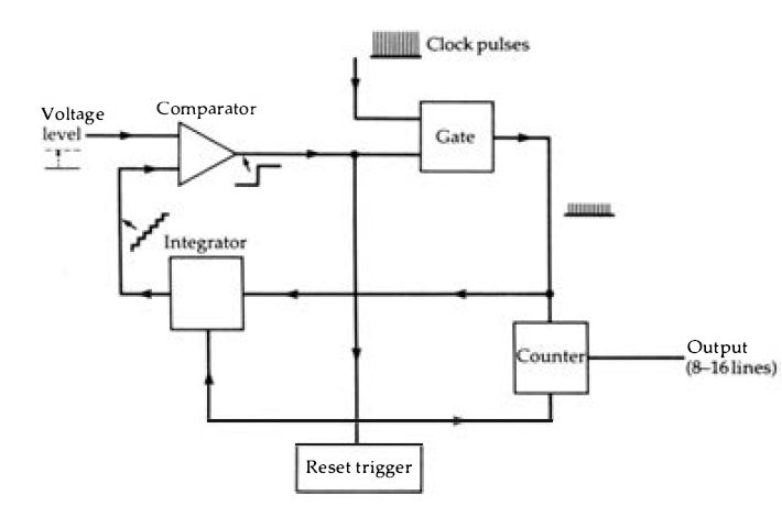
Figure 3.8 Principle of A-D conversion using an integrator and comparator.
The clock pulses are passed through the gate and are counted and integrated.
When the level of the integrated signal equals or exceeds the input signal
amplitude the comparator shuts off the gate . The output from the counter
(on a set of binary coded lines) can be read, and then the reset trigger will
reset the counter, integrator and gate . The amplitude of the input is assumed
to remain constant during the time needed for the count, so that a fast clock
rate is needed.
Conversion
The effect of sampling is only to quantize the signal . The signal is still an analog signal in which the variation of amplitude with time carries the information of the signal, and the change that has come about as a result of sampling it is the substitution of a set of pulses for the original smoothly varying (if any audio signal can be called smoothly-varying) signal . The signal is now an amplitude-modulated set of pulses at the sampling frequency --but this is not a digital signal. The actual conversion from analog to digital form is the crucial part of the whole encoding process . There is more than one method of achieving this conversion, and not all methods are equally easily applicable to digital audio. The important thing here is to understand the principles involved in the two main methods and the problems that each of them presents . We shall start with the integrator type of A-D converter as used also in digital voltmeters . The principle is simple enough, Figure 3.8. The central part of the circuit is a comparator, which has two inputs and one output . While one input remains below the level of the other, the output remains at one logic level, but the logic level at the output switches over when the input levels are reversed. The change at the inputs that is needed to achieve this can be very small, a matter of millivolts, so that the action as far as we are concerned is that the output switches over when the input levels are equal. If one input is the signal we are converting, this signal will be held at a steady level (by the sample and hold circuit) during the time that is needed for the conversion. A series of clock pulses are then applied both to a counter and to an integrating circuit . The output of the integrating circuit is a series of equal steps of voltage, rising by one step at each clock pulse, and this waveform is applied to the other input of the comparator. When the two inputs are at the same level (or the step waveform input just exceeds the sample input), the comparator switches over and this switch-over action can be used to interrupt the clock pulses, leaving the counter storing the number of pulses that arrived.
Now suppose that the steps of voltage were 1 m V, and that the sample voltage was 3. 145 volts. With the output of the integrator rising by 1 mV in each step, 3145 steps would be needed to achieve equality and so stop the count, and the count would be of the number 3145, a digital number that represents the amplitude of the voltage at the sampled input. The switch-over of the comparator can be used to store this number into a register as well as stopping the clock pulses. A master clock pulse can then reset the integrator output to zero and terminate the conversion ready to start again when a new sample has been taken.
These numbers are, of course, for illustrative purposes only, but they demonstrate well how a signal level can be converted into a digital number by this method. Note that even with this comparatively crude example, the number of steps is well in excess of the 256 that we could cope with using an 8-bit digital number. Note also that the time that is needed to achieve the conversion depends on how fast a count rate is used -- this will obviously need to be much faster than the sampling rate, since the conversion of each pulse should be completed by the time the next pulse is sampled . The quality of conversion by this method depends very heavily on how well the integrator performs . An integrator is a form of digital to analog (D-A) converter, so that we have the paradox here of using a D-A converter as an essential part of the A-D conversion process -- rather like the problem of the chicken and the egg. The very simple forms of integrator, like charging a capacitor through a resistor, are unsuitable because their linearity is not good enough. The height of each step must be equal, and in a capacitor charging system, the height of each step is less than that of the step previous to it. The integrator is therefore very often a full-blown D-A converter in integrated form, using the principles that we shall be looking at in the following section.
Now for the headaches . Assuming we havWe mastered the problems of achieving perfect integration with a D-A converter, can the circuit cope with the speed at which it will have to be operated? This speed depends on the time that is available between samples and the number of steps in the conversion. If we have 20µs available to deal with a maximum level of 65536 steps, then the clock rate for the step pulses must be: 65536 20 x 10^6 - which gives a frequency of 3.8 GHz (not Mhz), well above the limits of conventional digital equipment, and most other consumer equipment apart from satellite down-converters. This makes the simple form of integrator conversion impossible for the sampling rate and number of bits that we need to use for digital audio work, and we have to find ways around the problem. One method, if we want to stay with the integrator type of converter, is to split the action between two converters, each working with part of the voltage. The idea here is that one counter works in the range 0 to 255, and the other in units that are 256 times the steps of the first.
The voltage is therefore measured as two eight-bit numbers, each of which requires only 255 steps, so that the counting rate can be considerably lower. Since the counters work in succession, with the smaller range of counter operating only after the coarser step counter has finished (Figure 3.9), the total number of steps is 2 x 255 = 510, and the step rate is now, still assuming a 20µs time interval : 510 20 x 10^6 -- a rate of 25 .5 MHz . This may look a terrifying frequency if you are used to audio frequencies or indeed to the comparatively slow clock rates of the personal type of computer, but it is well within the range of modern digital circuitry in IC form.
Another form of A-D converter is known as the successive approximation type. The outline of the method is shown in Figure 3. 10, consisting of a serial input parallel output (SIPO) register, a set of latches (otherwise known as a PIPO register), a D-A converter and a comparator whose output is used to operate the register . This is a type of circuit whose action can be very obscure unless you go through it in easy steps, so we shall imagine what happens in the course of a sampling period.
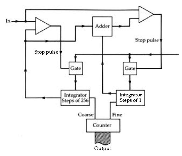
Figure 3.9 The principle of the two-step integrator system, details omitted
. The coarse step integrator produces an output whose level is the nearest
whole number of steps that is just less than the input, and this number is
counted to give the higher set of binary signals. The difference between this
output and the input is used to operate the fine step integrator to give the
lower set of bits. The coarse step comparator must be biased so that its output
will switch at a voltage lower than the actual input, and its output is also
used to start the fine-step integrator.
Imagine first of all that the output from the D-A converter is zero . and therefore less than the input signal at the time of the sample. The result of these two inputs to the comparator is to make the output of the comparator high, and the first clock pulse arriving at the SIPO register will switch on the first flip-flop of the PIPO register, making its output high to match the high input from the comparator. This first PIPO output is connected to the highest bit input of the D-A converter which for a 16-bit register corresponds to 32767 steps of amplitude.
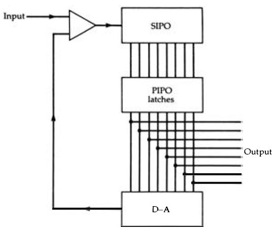
Figure 3.10 Principle of successive approximation A-D conversion. The PIPO
register is not of the conventional type, but consists of a set of flip-flops
to which the clock pulse is applied in sequence, not together. This allows
the outputs to be changed one after the other without affecting previous outputs.
Now what happens next depends on whether the input signal level is more than or less than the level of output from the D-A converter for this input number. If the input signal is less than this, the output of the comparator changes to zero, and this will in turn make the output of the SIPO register zero and the output of the PIPO register zero for this bit . If the input signal is greater than the output from the D-A circuit, then the 1 bit remains in the first place of the register. The clock pulse will then pass this pulse down to the next PIPO input - this does not, however, affect the first PIPO input which will remain set at the level it had attained . Another comparison is now made, this time between the input signal and the output of the D-A converter with another input bit . The D-A output will either be greater than or less than the input signal level, and as a result, the second bit in the PIPO register will be set to 1 or reset to 0. This second bit represents 16384 steps if its level is 1, zero if its level is 0. The process is repeated for all sixteen stages in the register until the digital number that is connected from the PIPO outputs to the D-A inputs makes the output of the D-A circuit equal to the level of the input signal.
Using this method, only 16 comparisons have to be made in the sampling period, giving a maximum time of 1.25µs for each operation. This time, however, includes the time needed for shifting bits along the registers, and it requires a fast performance from the D-A converter, faster than is easily obtained from most designs . Speed is the problem with most digital circuits, which is why there is a constant effort made to improve methods of manufacturing ICs, and even to alternative semiconductor materials (like gallium arsenide) that could allow faster operation.
Negative numbers
So far, we have been assuming that the numbers we work with are in the range of 0 to 65535, the range of a number that can be represented by sixteen bits. This makes no allowance for the use of negative numbers, but the amplitudes that we are dealing with will be alternately positive and negative. The binary number system makes no direct provision for the use of a negative sign, however, and any method that we use for converting denary numbers into binary must use one of the binary bits itself to represent a negative sign.
The convention that is adopted in computing is the very common one of 2' s complement, in which the highest order bit is used as a sign bit, 0 for positive and 1 for negative. The principle is illustrated in Figure 3.11 for a four-bit number, showing that numbers from 0000 to 0111 ( 0 to +7) will be positive and numbers from 1000 to 1111 (normally 8 to 15) will be negative. The way that the numbers progress, however, is slightly unexpected, because in this simple example, the value changes from +7 to -7 with the change from 0111 to 1000 . The value of a negative number is, in denary terms, the value of the number (ignoring sign) with 16 subtracted.
All this arises from the method that is used to form a negative number in this conventional binary system. The number must be in the range that does not use the highest-order bit, and the conversion to negative form is done by inverting the digits (changing 1 to 0 and 0 to 1) and then adding 1 to the lowest place . For a sixteen-bit number this implies that the range of positive numbers is from 0 to 32767 and the range of negative numbers is from -1 to -32768 . The same absolute range of 0 to 65535 is still being used, but split into positive and negative sections . The convention about how we regard a number does not affect the methods that are used for A-D conversion, and all we need to do is to ensure that the polarity of the signals will be such that negative voltage amplitudes generate numbers greater than 1000000000000000 in the A-D converter.
This method of representing a negative number, used almost...
Four bit range is -8 to + 7
Conversion of positive numbers as before for negative numbers 1 Convert as if positive 2 Invert each digit 3Add l 4 This is negative binary number For 4 bit number
0 00 1 0001 2 0010 3 0011 4 0100 5 0101 6 0110 7 0111
-8 1000
-7 1001
-6 1010
-5 1011
-4 1100
-3 1101
-2 1110
-1 1111 eg -6? +6 = 0110 eg 0110? 1001 eg 1001 + 1 = 1010

Figure 3.11 The 2's complement method of coding a negative number in 8-4-2-1
code . The most significant bit (left hand side) is used as a sign bit, rather
than just as a number bit. The conversion consists of converting regardless
of sign, and then for a negative number inverting and adding one . The sequence
of codes shows how the value changes violently with the change from 01 11
to 1000 in this example.
...universally in digital systems, brings its own headaches . A low-level signal, for example, will be changing from a small positive number such as 0000000000000001 to a small negative number such as 1000000000000001 in which just one bit, the most significant bit, has changed. The effect of this causes problems in the conversion from digital to analog, as we shall see later. The other problem lies in coding. All of these numbers are likely to contain long runs or either 0’s or 1’s, which will cause problems with any kind of recording system. This means that the number have to be converted, using a coding system which:
1. Does not allow long 'DC' intervals of identical bits.
2. Does not allow transitions to occur close to each other
This second condition needs more explanation. If any coding system allows a sequence such as 1010101 . ... to occur, there are bound to be problems with both recording and replaying because of the difficulty of correctly tracking such rapid changes -- remember the rate at which these pulses have to be read and written. Given these problems, then, the conversion to binary number is just one step in the record/replay system, and the binary numbers are neither recorded nor replayed directly. As we shall see, digital audio systems usually ignore negative numbers by using a method rather like the use of bias, taking a number midway between zero and maximum as the real zero, sometimes referred to as digital silence. Using this system, negative numbers have a most significant bit of zero and positive numbers have a most significant bit equal to 1.
Error checking Inevitably in any recording system there will be errors. On tape or disc there will be dropout errors where because of a tiny fault in the recording material some signals cannot be recorded. On magnetic tape, these dropouts will be caused by missing or poor quality magnetic coating, and though the incidence of dropouts can be made small it can never be eliminated; a similar situation arises in any method of disc recording. Analog recording suffers from dropouts, but if the dropouts are of very short duration they are virtually inaudible. For digital recording, however, the duration of a dropout could result in hundreds of digits being missed, making the problem more serious.
Another problem is jitter, analogous to wow and flutter in analog recording. Jitter means that the imperfect control of speed of the recording medium will cause alteration in the frequency with which signals are replayed, and if the system depends, as all digital systems do, on the maintenance of a set clock frequency, some method will have to be found of keeping this clock frequency in step with any jitter.
Another form of error is more subtle and specific to digital recording methods - it is called intersymbol interference.
However we record a pulse, it is most unlikely that the recorded form will be as narrow as the pulse was, whether the recorded form is a magnetic signal or a mark on a disc. This brings the danger that adjacent pulses can interfere with other, and is another reason for the requirement that we need to avoid sequences such as the 101010 ... type mentioned earlier.
Other forms of error are from the familiar old enemy of all recording, noise, whether caused by the analog parts of the processing, the digital portions, or by the effects of editing master tapes or even blunders in recording or processing at the studios . One of the problems of any digital number system, irrespective of the system used, is that an error that causes a 1 to change to 0 or 0 to 1 can make a very marked difference to a number . If the error takes place so as to affect a low order digit, this is not particularly serious - for example if the number 0110111001011011 (denary 28251) changes to 0110111001011010 (denary 28250), then the change is only one part in some twenty-eight thousand, negligible. If, however, the change is to a higher order bit, perhaps in the example above to 0010111001011011 (which is 11867 in denary) then the change is very large and the error is certainly not negligible. It is even more important if the change is to the highest order bit, changing the number from positive to negative or vice versa as well as changing its value . Any digital system must therefore make some provision for error checking, and for digital audio checking alone is not enough. There must be some type of provision made to correct any error, because the nature of all recording materials, whether tape or disc, must be that bits of digital numbers will inevitably go missing. In using tape we always have the problem of dropouts and drop-ins which will affect the recording and reading of digital numbers, and on discs we have the problems of scratches and other imperfections of the surface. A scratched disc may make a noticeable noise in an analog replay, but it can make a very much greater impact on a stored number, though this may, as we shall see, not be quite such a significant part of the waveform.
At this stage, we shall not go deeply into error detection and correction, because this is one of the most difficult aspects of digital audio and one that most users never come across because the whole process is controlled as part of the signal processing system.
We need, however, to know the principles that are involved. These boil down to digit counting, redundancy and level maintenance . Digit counting is a method of checking for the presence of one incorrect digit, and the simplest system is the parity system as used on serial transmission links between computers and printers . We noted this in section 1, but a concrete example will make the advantages and disadvantages more clear. Suppose, for the sake of simplicity, that we are dealing with numbers of three digits only, in the range 000 to 111. Now such numbers can contain either an even or an odd number of 1's, like 001 and 011, and the presence of an odd or even number of l's can be detected very simply by a set of XOR gates . Achieving parity means adding an extra bit so that all numbers contain either an even or an odd number of 1's.
In the even parity system, each number is made up with an extra digit (placed in the highest position) which will make the number of l's always even. This the number sequence of our example, 000, 001, 011, 100, 101, 110, 111 would become 0000, 1001, 0011, 1100, 1101, 0110, 1111 respectively. If we chose an odd parity system, each number would need to contain an odd number of 1's, so that the number sequence would become 1000, 0001, 1011, 0100, 1101, 1110, 0111. For many purposes, this is better because it excludes the 0000 case, making all numbers consist of 0’s and 1's.
Parity is at its most effective when it is used for small groups of digits, and it can be quite effective in detecting single-bit errors even in eight-bit numbers. It is by no means a method that we could use directly for a digital audio system, however. A simple parity system can only detect the fact that a single bit has changed, it cannot detect which bit, it cannot detect more than one change and it cannot correct any change. As we shall see, however, the principle can be useful when a number can be broken down into groups of bits, and where (as in all digital numbers in binary scale) some bits are much more important than others . Redundancy is another very important method of detection and correction. In its crudest terms it could mean that each and every number was recorded three times, and the receiving circuits arranged so as to take a 'majority vote' on the correct number if the three versions did not agree. A simpler method would be to record each number twice, with parity included, and exclude the number with a parity error. The simplest and most effective redundancy systems, however, are very wasteful of storage space, and we have to think carefully about what we want to correct . Since the higher order bits in a number convey larger changes in amplitude, it makes sense to employ more redundancy on them than on the lower-order bits . Like so many aspects of communications by way of digital numbers, redundancy has received close attention from theorists, and is now a very formidable subject in its own right. In this guide, therefore, we shall do no more than skim the surface, particularly as regards the complicated systems that have been evolved for compact disc error detection and correction.
Level maintenance is the backstop of support for error correction. If an error has been detected but cannot be corrected, then a level maintenance system discards the number that is in error, and retains the number that was present just previously. The sampling rate for conversion of an audio signal is such that the amplitude difference between two samples will always be very small (even in Aaron Copeland's Fanfare for the Common Man!), so that retaining the previous amplitude value is usually preferable to changing to an incorrect amplitude value, particularly if the change would be a large one. This can even be made the basis of error detection on the basis that no amplitude change from one sample to the next can ever exceed a preset amount. Another possibility here is to use the previous signal with a small dither (noise) signal added, and this gives an even better correction for some types of signals . Yet another possibility is interpolation, in which the amplitude difference between the two previous signals that were not subject to error is added to the signal previous to the error, as outlined in Figure 3.12.
n 14605 n+1 14622 difference = 17 n+2
-22 error signaled use 14622 +17
= 14639 n+3 14655

Figure 3.12 The basis of interpolation. As numbers are read, a circuit finds
the difference and stores this. If a new number is signaled as an error, a
corrected number is formed by adding the difference (stored from the previous
pair) to the last correct value . Even after several interpolations, the waveform
shape will not be too seriously affected.