In transmitting digital information from one device or instrument to another, noise spikes and other interfering electrical signals can cause errors. A positive-going noise spike can cause a 1 to appear where a 0 should be; a negative-going spike may wipe out a 1, causing a 0 to appear instead.
A little noise on an analog signal ( such as a voice message or a musical recording) causes a slight degradation in the quality and/or intelligibility of the message, but it does not make it wrong. An error in a digital signal, however, can create extremely wrong interpretations. If a computer tells a machine to add $10 to one account and deduct $10 from another account, but the machine at the end of the line gets a command to deduct $1,000,000 from one account and pay it to another, a monumental error has occurred.
An error of $1,000,000 in the transfer of funds is not likely to go unnoticed for long and, thus, the system's problem of transferring funds tends to be self-correcting. But what if an error of only a few dollars occurs? This may go unnoticed. In other cases, errors can be far more dangerous and difficult to detect. What about a computer that is controlling an atomic reactor? Or a Boeing 747? In critical cases, an error-detecting scheme of some sort is vital.
Many error-detecting and correcting schemes have been devised. One of the easiest ways is to transmit the same message twice and compare the two received messages bit by bit to make sure they correspond. If they don't, the message can be transmitted again and again.
Another method is to use a Hamming code. In this technique, extra bits are inserted into the message in such a way that transmission errors can not only be detected but also corrected.
The capability for correcting a wrong message arises from the redundancy supplied by the extra bits.
PARITY GENERATOR
One of the simplest and most economical error-detecting schemes is the use of parity bits. Assume you are sending a 3 bit message which can consist of any word from 000 to 111.
Now, add a special fourth bit of such a value that the number of is transmitted is always an even amount. The word trans mitted will then be as shown in Fig. 8-1. The extra bit is called a parity bit since it assures that all the words are on a par with...
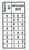
Fig. 8-1. Message bit with parity bit added.
...respect to whether they have an even number or an odd number of is. When the message is received, a parity check is performed. If there are an even number of is, the word is assumed to be correct. The parity bit, whether 0 or 1, is then discarded.
Obviously, the parity formula can be changed so that the number of transmitted is add up to an odd number instead of an even number. Odd parity, as it is called, is used more often then even parity since odd parity requires at least one 1 in every word, even if the data word is 000. A circuit to test an 8-bit word for parity and to generate the required parity bit is shown in Fig. 8-2. The device, circuit type 54180/74180 IC, will generate even or odd parity. The OR and NOR gates with the extra curved input symbol are exclusive-OR or exclusive-NOR gates; that is, the output is true only if at least one input is true but not the other.
Line 1 of the analysis table ( Fig. 8-3) shows both Parity Select inputs low, which causes both outputs to be high, regard-
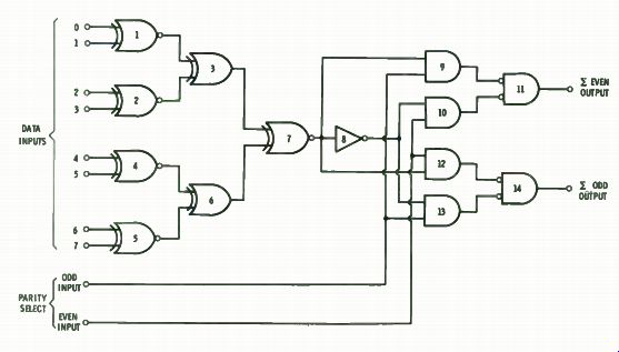
Fig. 8-2. An 8-bit odd/even parity generator/checker circuit.
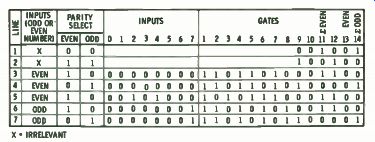
Fig. 8-3 Analysis table for Fig. 8-2.
-less of the number of input bits. Line 2 shows both Select in puts high, which drives both outputs low.
Line 3 shows all input bits low or 0, and thus the number of is in the message is 0 or even. With Even Parity Select high, the internal gates take up the states shown; the output marked Even ( Gate 11) will be high; and output Odd ( Gate 14) ...
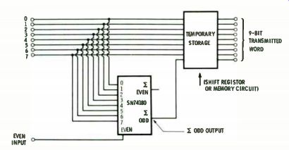
Fig. 8-4. Circuit for adding parity bit.
... will be low. Since a 0 is required for the parity bit, the output of Gate 14 can be added to the transmitted word as indicated in Fig. 8-4. The Temporary Storage shown in Fig. 8-4 can be a shift register, a memory circuit, or other circuit. For example, if the word is to be transmitted serially, a multiplexer can be used to hold the word plus its parity bit.
Line 4 shows the circuit when the Odd Parity Select line is left high, while line 5 simply shows that the scheme holds when the number of 1s is increased to two. Lines 6 and 7 show input words with an odd number of bits.
When the word with parity bit is received, it is tested by a parity tree similar to Gates 1 through 7, except that an extra bit must be examined. If the predetermined parity-odd or even- is found to be correct, the transmission is assumed to be correct. Note, however, that this scheme will not catch a word in which two bits are wrong (two is or 0s interchanged, or two is added or subtracted). More elaborate parity checks and special codes can be used to detect multiple errors.
PRIORITY ENCODER
An aircraft is coming in for a landing under control of its autopilot. The height-above-ground measuring system tells the control computer that the plane is too high for its position on the glide slope; therefore, something should be done about it (such as nosing down a little, lowering the flaps a little more, or reducing engine speed). At the same time, the speed-measuring system is telling the control system that the airspeed has fallen too close to the stall-out limit, and that something must be done about it also ( such as increasing engine speed, or raising the flaps, etc.). Obviously, it is impossible to increase and decrease engine speed at the same time, so the control system must choose which of the two situations is the most important and act accordingly.
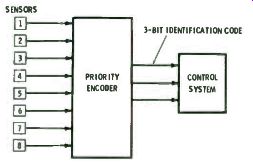
Fig. 8-5. Priority control system.
A basic control scheme for a system monitoring eight variables is shown in Fig. 8-5. The variables may be oil tempera ture, fuel-flow rate, boiler pressure, etc. If oil temperature rises too high, the bearings of a large expensive machine will experience excess wear. If the fuel-flow rate rises too high, it is a signal that fuel is being wasted by a leak or poor combustion.
If the boiler pressure rises too high, the boiler can explode and destroy the entire system. In a situation like this, we would assign the highest priority to high boiler pressure. As soon as it exceeded its preset limit, we would want the control system to act to reduce the boiler pressure, no matter what this might do to the other variables. In designing a control system, there fore, limits are determined for all the variables. Then, priori ties are assigned so that the control system knows which operation to perform when it is asked to do two or more contradictory things at the same time.
The priority encoder shown in Fig. 8-6 has 8 active low in puts and 3 outputs. Input 7 has the highest priority. Whenever ...

(A) Logic diagram. (B) Truth table.
Fig. 8-6. Eight-input priority encoder.
... it is low, the output generates the 3-bit word 000, regardless of the states of the other inputs. If input 7 is high, the encoder will produce an output corresponding to the next lowest priority input. If only 1 input is active, the encoder responds with the corresponding output as shown in the truth table. If two or more inputs are active, the output produces the code for the input having the highest priority.
Input EI is an enabling or clock input. Output gate GS is a group output which goes to 0 when one or more of the 8 inputs is active. Output GS is a 1 if all inputs are inactive. Output EO combines the information from input Pi and output CS. When enable input KT goes low--which constitutes an interrogation of the encoder--EO goes low if all inputs are inactive and high if one or more is active.
Circuit operation is as follows: When input EI is high, it puts Os on Gates 1 through 8 and Gate GS. This, in turn, puts Os on Gates AO, A1, and A2, driving them to 1. Gate 8, with a 0 input, is driven to 1, and Gate GS, with a 0 input, is 1. Thus, all outputs are high.
When input EI goes low, it removes its inhibiting affect and allows the gates to follow their other inputs. If input 51 is active (that is, 0), Gate 8 is driven to 1; therefore, Gate GS has two is as inputs and is driven to 0, while EO is 1. Gates 1 through 7 all have one or more inputs = 0 and, thus, these gates remain at 0. Output gates A0, A1, and A2 are not affected.
With input EI low, let input T = 0 (with the other inputs inactive). Gate 8 and EO go to 1 and n goes to 0. Gate 1 now has all inputs = 1 and goes to 1; Gate AO goes to 0. Gates 2 through 7 all have at least one input = 0, and they are not affected. Gates Al and A2 stay high. If, in addition to 1 = 0, in put Z5. also = 0, no change in the output occurs; the priority of input T over input - b has been identified.
As the other inputs become active, the circuit responds similarly, producing the 3-bit output code shown in the truth table.
Priority levels can be increased by using more encoders as shown in Fig. 8-7. More inputs can be handled by using more encoders in a similar manner.
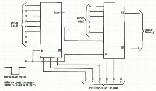
Fig. 8-7. Diagram for expanded encoder operation.
Prev: Link | --Link | --Link | --Link | --Link | --ARITHMETIC CIRCUITS
Next: MEMORIES
Guide Index : Transistor-Transistor Logic (early 1970s)