- Intro
- GUEST EDITORIAL
- AUDIO CRITICISM AND THE AUDIO AMATEUR, By Gary Galo
- AUDIO AIDS, By Dick Moore, Larry Cartwright, A. Nehan and Stephen Nitikman
- CLASSIC CIRCUITRY--CLASSIC TUBE TESTERS, By Alan S. Douglas
- SHOWCASE An Eighteen Foot Rack System, By Neelam Makhija
- JUST LOOKING
- LETTERS
INTRO
The Compact Disk (CD) is, as you may have guessed from our cover, the dominant theme for this issue.
Walt Jung, whose return to the staff of this magazine as Contributing Editor we announce with great pleasure, has been deeply involved in observing how integrated circuits affect the performance of the compact disc players. Some of the results of his work is here.
On the other side of the Atlantic, Alan Watling has added a compact disk player to his system and finds that this electronic “new kid on the block ” necessitates some major changes in how his system is config'd, and uncovers some hitherto hidden anomalies. His account of the saga begins here.
When Hampton Childress, the Baltimore Symphony's second principal contra id began audition other orchestras' work on how a new compact disk player, he heard rumors that it could sound a lot better. Since Baltimore and suburbs are full of audio amateurs, he was soon working with fellow enthusiasts, including Walt Jung, on upgrading his Yamaha CD2.
Hafler components follow in the great Dynaco and Eico tradition of being exceptionally attractive modification candidates, rather like stock car preferences for certain vintage Fords and Chevvies. Daniel Coyle has done a new mod of the popular Hafler DH-100 pre amp.
The editor's anglophile bent is well known. Apposite nomenclature, respectful signs, and healthy group activities are some of the reasons. Another is Britain's coalition of recorded music listeners. Reg Williamson, one of the magazine's original editors, tells us all about The Gramophone Society.
Ben Poehland reviews an inexpensive kit he constructed which traces signals in all sorts of circuitry: A BROADBAND SIGNAL SNIFFER
G. Galo is our guest editor this time, taking aim at the too often arrogant messianism that affects some high end advocates. See below.
This issue carries an unusually rich Audio Aids section (see below) from Dick Moore, Cartwright, A. Nehan and Steve Nitikman. Be sure you see Alan Douglas' essay on and showcase of tube testers (see below).
Editorial--AUDIO CRITICISM AND THE AUDIO AMATEUR
Editor Dell's commentary on the reviewing policies of the three mass-circulation hi-fi magazines (TAA 1/85) was a necessary, if unpleasant, reminder that the audio reviewing situation in the US has not improved at all since his 'White Paper' on the same subject (TAA 3/74). In fact, the situation may well worsen, now that Stereo Review has been purchased by CBS.
Audio amateurs have every reason to be concerned with Stereo Review's increasing number of attacks on the high-end audio community, since most of its readers are builders of higher end equipment. I think it is safe to say even the more modest projects published in TAA (and, of course, its sister publication, Speaker Builder) offer higher performance than the typical mass-market Japanese fare reviewed by Stereo Review, Audio and High Fidelity.
There may be exceptions to this statement, but consider such TAA “classics” as Reg Williamson's amplifiers, which have offered respectable performance for many years. How can such designs be compared to products from Pioneer, Kenwood, Sansui, and the rest (their advertising supports the Big Three), whose designs are in need of an overhaul every six months, and whose pinball machine-like front panels seem more important than the circuitry itself? The very idea that 'all amplifiers sound alike' is an insult to those of us who take pride in the excellence of our hand-crafted audio equipment. The insult could be forgiven if it came from well meaning sources, but a re-reading of Ed Dell's 1974 editorial reveals some of the sources are not well meaning. Indeed, writers for some publications have virtually admitted to catering to their advertisers' whims, at the expense of their readers.
Lest this appear to be a one-sided discussion in favor of high-end audio, hand-crafted or otherwise, I think it is important to discuss another issue of major concern to myself and to others involved in the audio craft: the arrogance and self-righteousness of salespeople, reviewers, and, in fewer cases, the manufactures of high-end equipment. The high end audio industry is no collective saint, and the same can be said for many of the high-end (read “underground”, or whatever) publications.
I often visit high-end audio shops during my semi annual visits to New York City (when I am able to tear myself away from Tower Records). I have a genuine interest in what manufacturers at the forefront of sound reproduction are designing. I also enjoy an informative discussion (a two-way exchange of ideas) with others involved in audio, including salespeople.
Such discussions, however, are seldom found in high-end audio shops. The salespeople are often arrogant and condescending. Technical discussions are out of order; the mysticism of high-end must permeate the atmosphere. Techno-freaks, it is inferred, are not involved in the building of the equipment. At the factory, presumably, an Ayatollah bows to the East when the moon is in proper phase, and the latest $25,000 loudspeaker system miraculously appears before him.
Eventually, the salesperson discovers that I build (and, in some cases, design) my own equipment. I get several reactions, including: “It is a shame you cannot afford to buy high performance equipment ”, and/or, You are obviously more interested in technology than music' (With all due modesty, my musical training and experience invariably exceeds that of the salesperson.) I recall a visit to a well-established high-end shop in White Plains, NY. I asked the salesman to play the Erich Leinsdorf Wagner (on Sheffield Direct to Disc), one of the most spectacular orchestral recordings I have ever heard. He would not hear of it.
“Audiophile” recordings, I was told, do not contain good performances, and true music lovers have no interest in them. I agreed most “audiophile ” recordings do not contain definitive versions of a particular work, but, like the Leinsdorf Wagner, there are exceptions. I also pointed out Leinsdorf has been conducting Wagner in the world's major opera houses for more than 45 years, and that this particular recording was musically outstanding.
It was all to no avail. I'm sure the salesman dismissed me as a musically illiterate techno-freak.
Some high-end audio publications are equally arrogant. This attitude is often found in replies to reader letters and manufacturer comments.
The editor of Absolute Sound, for example, often deals insulting and contemptuous remarks to intelligent, well-meaning readers when they dare question his authority. International Audio Review has a different solution. They don't print letters at all, the thoughts of mere mortals being unworthy of inclusion on their pages.
In my experience, such responses are the result of insecurity. This, in turn, leads to opinions based on emotion rather than rational judgment.
Digital recording is one such issue where emotions have filled the air. I have made many of my recent live recordings in simultaneous analog and digital versions. I have played the results for the performers, audiophiles, and other musicians, and have been amazed at their sane, rational comments. Opinions have not always been pro or con in either direction, and nearly everyone found strengths and weaknesses in both formats.
In no case, however, did I hear anything resembling the emotional tirades that digital recording provokes in too many high-end publications.
One magazine refreshingly free of these traits is the original “under grounder”, Stereophile, which epitomizes sane, rational equipment re viewing. They never resort to arrogance, condescension, and emotionalism. They speak to their readers, not down to them.
Although Stereophile rarely publishes construction-oriented articles (its readers have not been enthusiastic about such things in the past), they have a strongly favorable attitude toward audio craftsmen. Much more important, they are willing to admit when they are wrong.
Another publication which de serves more recognition is Sensible Sound. Recognizing that most music lovers are not independently wealthy, Sensible Sound concentrates on af fordable audio equipment. Many of its editorial attitudes reflect those of Stereophile. I do not mean to imply I am always in agreement with either publication, but their methods and attitudes command respect.
We audio craftsmen have every reason to take pride in the equipment we design and build. The pages of Audio Amateur and Speaker Builder provide a unique forum for exchanging ideas: author to author, between author and reader, and reader to reader. Our greatest collective asset is our recognition we have not yet arrived at perfection, that improvement is always possible, and that there may be more than one valid approach to improvement.
There may be little audio amateurs can do to change the attitudes of some high-end publications and sales people, but we who share our interests on these pages can, I hope, rise above those attitudes and set a better example.
ABOUT THE AUTHOR: Gary Galo is an audio engineer at the Crane School of Music, State University College of Arts and Science, Potsdam, NY, where he also teaches courses in sound recording and audio technology. For five summers, he has been on the faculty of the Saratoga-Potsdam Choral Institute, having taught courses on high fidelity, opera, and recording history. Mr. Galo has a B.M. in Music Education and an M.A. in Music History and Literature from SUNY-Potsdam.
He has a large record collection, consisting of more than 2000 LPs and 2500 78s, with an emphasis on operatic and symphonic music. Mr. Galo is also active in performing music, having recently conducted the Crane Opera production of Purcell's Dido and Aeneas, and the Crane Faculty Artist Series' production of Lied der Waldtaube from Schoenberg's Gurrelieder.
He is a member of the Audio Engineering Society, the College Music Society, the Association for Recorded Sound Collections and the Gustav Mahler Society.
AUDIO AIDS
A BEST-FIT PROGRAM FOR RESISTIVE VOLTAGE DIVIDERS
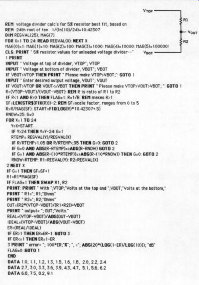
I WILL BET THAT other TAA readers have the need, as I do, for making resistive voltage dividers. Trying combinations with a calculator is tedious, so I decided to let my computer do it. This program (listed below) calculates the best-fit resistor values for an unloaded divider, using the 5 pc resistor series.
The X variable FOR-NEXT loop contains IF statements that throw out resistor values worse than 5% in error, and that saves the progressively better fitting values until the 5% resistor series is exhausted. A starting point for the value of the lower resistor (Y) is deter mined in the START variable. This eliminates a second FOR-NEXT loop for the variable and saves a lot of calculations, making the program run faster.
The results are displayed with one of the two resistors in the 1-9.10 decade. The resulting error is displayed both in per cent and decibels. The user can scale the resistors up to any desiied decade.
The program is in MS BASIC 2.0 for the Macintosh. It transports to any dialect of BASIC, but the user may need to re-write the line that finds the scale factor:
SF - LEN(STR$(FIX(RFINAL))) -2
and the line that calculates the START variable, using INT instead of FiX. Also, note the line that contains the SWAP command, this just exchanges Ri and R2. For many machines, the variable names will need to be shortened to two characters and line numbers will need to be inserted. I think you may be sw prised at just bow accurate dividers made from 5% values can be. But remember, the values are for unloaded dividers.
Dick Mooret; Jonesboro, AR 72401
REFERENCE: “Program Speeds Best-Fit..., ” EDN, JULY, 25, 1985.
BEST-FIT PROGRAM FOR PARALLELED RESISTORS
NECESSITY is A mother, and she drove me to write the following short program to find a resistor value by paralleling two standard 5% values. The program finds the best-fit combination of 5% resistors to give the value desired, and also shows the error, based on using exact 5% values.
The program shows intermediate values that qualify as a good fit (less than 0.5% error) so that the user has a selection of values to work with. The pro gram also automatically normalizes the user-input resistor value to the 1-9.99 ohm decade and then scales the best- fit output values back to the original size of the input value.
The program is great for those who have Old Colony's 1%, E-24 metal film resistor assortment, since any standard 1%valuecanbehadfromthe5% series with less than 0.25% error. I have in- clued a print out of the 1% values (Table 1) and 5% combinations, which may be of interest to those who do not want to rewrite the program themselves.
While most TAA readers probably have not been attracted to the Apple Macintosh, I was and the program is in MS BASIC 2.0: hence the nice print out. The program will probably transport easily to dialect of BASIC, with the ...
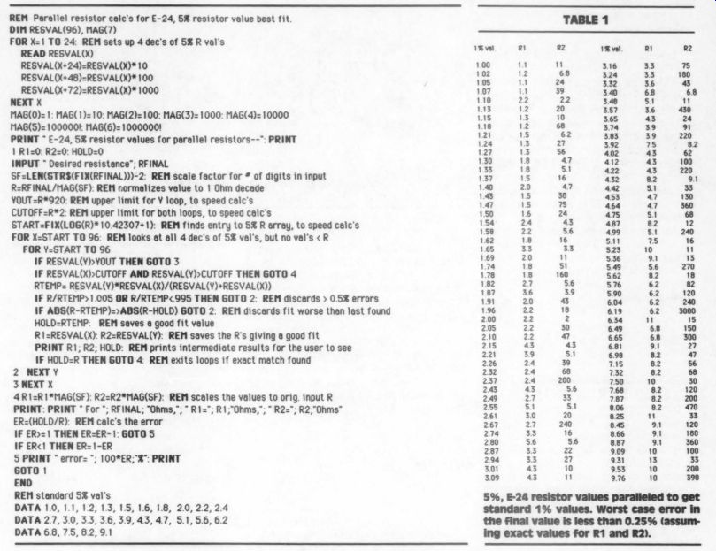
Table 1: 5%, E-24 resistor values paralleled to get standard 1% values. Worst case error in the final value is less than 0.25% (assuming exact values for R1 and R2).
... possible exception of the line that finds the scale factor of the input resistor value:
SF = LEN(STR$(FIX(RFINAL))) – 2
and the line that calculates the start variable. Some BASICs, like Commodore's, use the INT function instead of FIX. Finally, for most machines, the variable names will need to be shortened to two characters and line numbers will need to be inserted. The START variable for entry into the 5% value array is calculated using the inverse of the 24th root of ten (10.42307). A round-up function is provided by adding a 1.
Usually little is said about numerical accuracy in computers. As written, the program used 'single precision’ arithmetic which works well. Accuracy problems should not be encountered with most computers.
Dick Moore Jonesboro, AR 72401
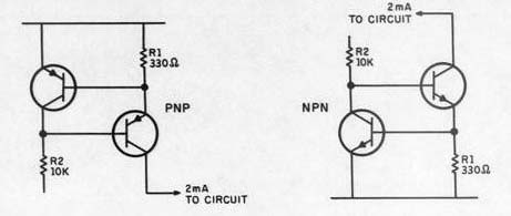
FIGURE 1: The circuit schematic for my constant current source. The transistors are general purpose high-gain types.
ONE LARGE BOARD --- If you are ADDING bypass or coupling capacitors to a circuit, you may be faced with the problem of where and how to mount them. Most polypropylene capacitors are too large to easily solder to a normal size circuit board. When you bypass power supply capacitors, terminal strips must be added or the bypass caps must be strapped to the large electrolytics.
I have designed a simple two-channel circuit board (Fig. 1) to solve these problems. It accommodates most capacitor sizes from small polystyrenes to large WonderCaps. The circuit is designed so that the input/output wires are on the same edge of the board, for use as bypass capacitors, or are on opposite edges, when used as coupling capacitors.
The board also has two handy through-ground paths for soldering shields in the coupling configuration.
The board is designed to be easily cut in half for two single boards. Mounting holes are indicated for either single or dual mounting.
LARRY CARTWRIGHT, Pittsburgh, PA 15213. Readers interested in obtaining this circuit board (estimated cost $5) . If enough interest is shown you will be notified of availability.
A CONSTANT SOURCE CURRENT
I HAVE A LITTLE known constant current source which may be of interest to readers. Its circuit diagram is shown below. I measured the circuit's dynamic resistance using high-gain transistors (BC182s) at 2mA, and found it to exceed 1 M-OHM. Resistor R1 is chosen for the desired current (R1=0.7/desired current in amps). R2 is a high-value resistor (typically 10k), but the exact value is not critical. I have not carried out detailed experiments to measure the circuit's temperature dependence, but limited experiments indicate little dependence.
A. NEHAN London, England
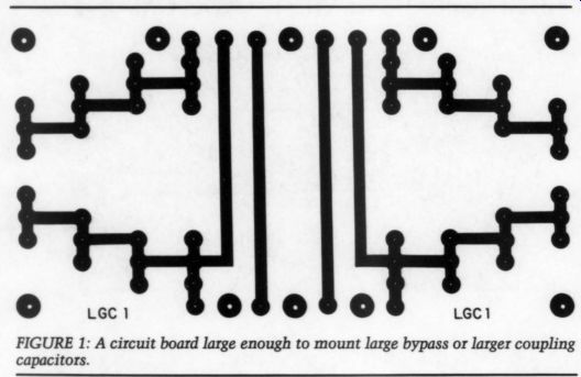
Fig. 1
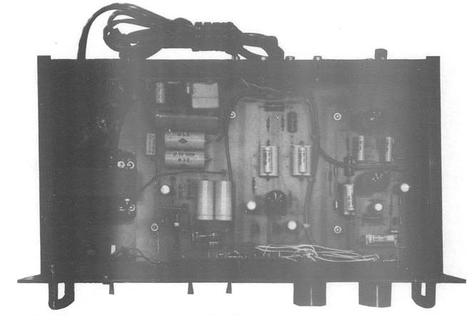
PHOTO 1: The author's preamp features a turn-on delay that mutes transients.
PREMIER PREAMP
I AM QUITE PROUD of this vacuum tube preamplifier, which features an IC regulated, high-voltage supply and audio-grade parts throughout. Although it uses only three tubes, performance is excellent. Noise is very low and hum inaudible.
I did not use any shielded wire, but made all the connections front to back via a strip of circuit board underneath the main circuit board. The design is a simple cascade circuit using a 12AX7 (both channels phono), a 6DJ8 (second stage, both phono channels) and one 6DJ8 for both channels of line amplification.
I designed the circuit board layout.
That small board mounted on the back left side is a turn-on delay I designed (using a 555 timer and relay) to mute the output for 15 seconds after turn-on.
STEPHEN NITIKMAN; Don Mills, Ontario M3B 2P9 Canada
CLASSIC CIRCUITRY
Classic Tube Testers
BY ALAN S. DOUGLAS
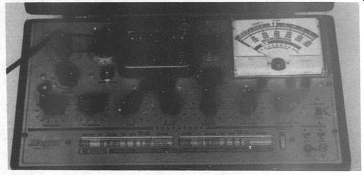
PHOTO 1: Author Douglas' reliable Hickok 6000A.
Good Tube TESTERS HAVE always been very expensive. 20 years ago, $150 wouldn't have bought you very much, and some common models sold for $500. But now that tube equipment has virtually disappeared, tube testers can be bought second-hand for a reasonable price.
There are two basic types: emission testers and mutual conductance testers.
Emission types, which are much less ex pensive, apply a voltage to all grids and plates tied together, and measure the total cathode current (the better designs apply different voltages to various ele ments and measure only the plate cur rent). Though an emission check will cull the obviously-worn-out tubes, it tells only half the story. A mutual con ductance tester actually measures the amplification, applying a small AC signal to the grid and measuring the amplified signal at the plate. Simpler models use 60Hz AC as a signal. The more elaborate ones contain an audio oscillator and apply correct DC voltages to every tube element, using panel meters for monitoring.
Since a good mutual conductance tester costs no more now than a cheap emission tester, there is really no excuse for owning anything else. A go of different brands were available in the 1950s and 1960s, but Hickoks turn up most commonly now.
The key words to look for are 'mutual conductance ” or “transconductance ”.
Don't be fooled by “plate conductance” or “Gp ”, or the word “dynamic”. There were also hybrid designs: one, for in stance, measured mutual conductance on the more common tubes, and emission on the rest. Rectifiers are always tested by emission only. There were also a number of mechanical designs: testers with lever switches, rotary switches, an array of pre-wired sockets and no switches, punch-card testers, and even a patch panel-all to connect the right tube elements to the right voltage sup plies. Speed in setting up a tube was once quite important to TV servicemen but is less so today.
Obviously, a tester made before the introduction of Nuvistors and Compactrons will not have sockets for either.
This may or may not matter to you (lat Magnecords used Compactrons).
Of the four tube testers I now own one was free, two cost $20 apiece, and one cost $150 20 years ago (and has more than paid for itself). The 6000A is my ol trusty standby.
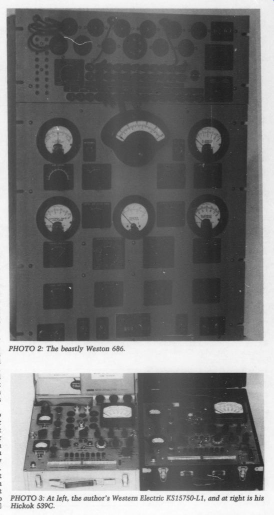
PHOTO 3: At left, the author's Western Electric KS15750-L1, and at right
is his Hickok 539C.

FIGURE 1: A variety of listings from a 1965 Allied catalog.
The Western Electric version of the 539 cost $20 through a newspaper ad, but did not work. Hickok was extremely helpful in supplying me a copy of their factory calibration procedure so I could repair the tester. Three of its precision wirewound resistors had opened, and I also had to repair a bad soldered joint in the moving coil of one meter. Since then, it has worked fine. It has all the Western Electric house-number tubes on its roll chart, and also has a few refinements lacking in the commercial 539, such as a cathode-bias decade resistance.
I found the 539C at an antique-radio flea market, and it worked as promised.
I walked past it several times, in ever smaller circles, but just couldn't leave it there for only $20.
The Weston analyzer Model 686 type 10A was free for the hauling (if you carry one by yourself, be sure your medical insurance is paid up). You wouldn't want to use this one for routine testing because there are no charts with it. In stead, you set it up by the tube manual.
Every element has a separate metered supply, but it will duplicate any operating condition (up to its 100mA maximum plate-current capability).
I have used it, for example, to find a 6CA?7 that tested perfectly normal, but would eventually run away at full plate current and glow cherry-red in my Dynaco. The only trouble I've had with the Weston was an open pot in the screen supply: a 20k, 150W Ohmite with incredibly fine wire windings (because a replacement would cost more than the whole analyzer was worth, I made my own from a 40-step attenuator and fixed resistors).
I have heard that Hickok won't respond to inquiries on old tube testers, but I've had nothing but good luck with them. Their address: Hickok Electrical Instrument Co., Dupont Ave. and E. 105th St., Cleveland, OH 44108. Roll charts are, of course, not available. What they will sell you is a chart reprint in book form, which is only slightly less convenient than the rolled version.
If you find roll charts, they tend to shred with use, especially as the paper ages. There is nothing you can do about it except avoid rolling them whenever possible. Torn edges can be taped with transparent tape (don't stretch it when applying), though you will probably regret it ten or 20 years from now.
Mending tissue works better. Your best bet is to make a copy of a roll chart in page form and use that, or attach a chart of the most commonly-tested tubes to the lid of your tester.
SHOWCASE
AN EIGHTEEN FOOT RACK SYSTEM
by Neelam Makhija
My AUDIO PROCESSING System, as shown in Photo 1, took five years to complete, and some portions have yet to be finished.
The equipment is a mixture of solid state and vacuum tube electronics. The three six-foot racks are cased with pine boards.
The first rack (left) comprises two Crown 800 reel-to-reel tape recorders.
The electronics were modified using discrete op amp cards as gain elements, Resista resistors, WonderCaps and many more quality components. A modified TEAC outboard, Dolby B unit is for recordings that require improved signal to-noise performance. A 200W per channel amplifier completes this rack.
The second rack houses audio signal processing components. The Class A amplifier, at the bottom, feeds 20W per channel to the Decca ribbon tweeters.
The third rack (right) incorporates audiophile-quality vacuum tube elec tronics. My tube preamplifier (Photo 2) uses an outboard tube-regulated power supply to feed a tube electronic cross over (crossed at 400Hz) to a modified Dynaco Stereo 70 power amplifier and the Amp jr. (a low-impedance high current bass driver amplifier).
The Dynaco feeds the six Strathearn line drivers. My ambient speakers (Bose 901s) are fed by an analog delay line, going on into a single-channel 70W amplifier. Three cassette decks and an outboard Dolby 'C' processor complete the unit.
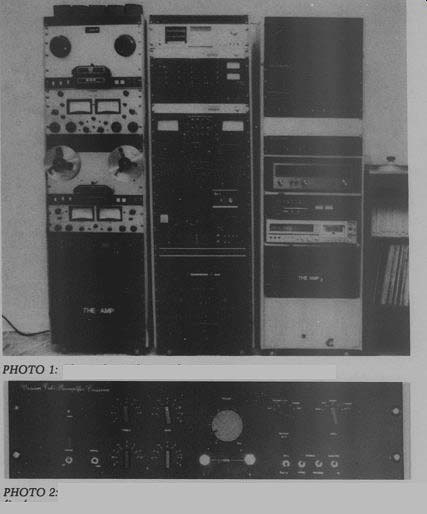
PHOTO 1: The author's three-rack system. PHOTO 2: Closeup view of the front panels of the author's tube-type preamplifier/crossover (above) and his high current bass amplifier.
Just Looking
The Meitner Audio PA-6 preamplifier, under development for more than three years, is now available through Assemblage.
The PA-6 employs a custom-designed VCA (voltage controlled amplifier) to control volume and balance, and cur rent-mode switches to route all audio signals. Circuitry is fully DC coupled, with no coupling capacitors in the signal path.
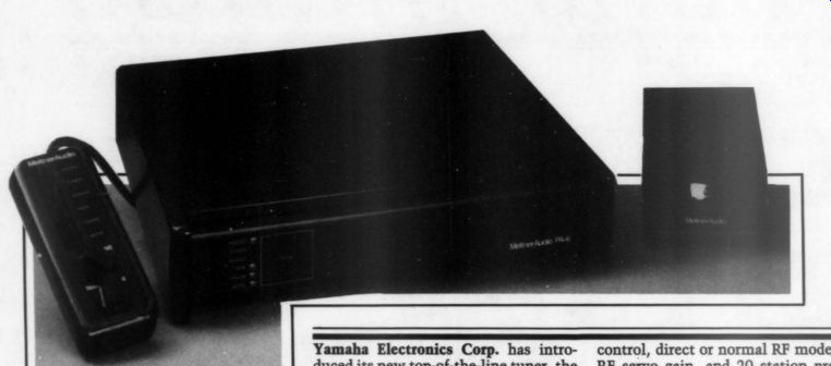
The wired remote provides switching of all inputs, mute, volume, balance, and absolute phase inversion. In addition, the PA-6 features three inter changeable phono interfaces: one for moving coil cartridges, one MMLZ for medium-resistance and moderate-inductance cartridges, and a negative impedance MM which allows moving mag net cartridges to perform at their best.
Both the MC and MM interfaces amplify current, and provide the cartridge with optimum load and damping.
For more details, contact Assemblage, PO Box 815, Branford, CT 06405.
Yamaha Electronics Corp. has introduced its new top-of-the-line tuner, the T-85. Key feature is the new Yamaha developed Computer Servo Lock tuning system, which incorporates two different methods of tuning to obtain the most accurate and best-sounding radio signal possible.
In addition to CSL, the T-85 includes a digital fine tuning feature for “detuning” an FM signal in 0.01 MHz steps.
This feature permits compensation for slightly misadjusted transmissions and multipath reflections.
Other features include a four-position selectable or automatic IF bandwidth control, direct or normal RF mode and RF servo gain, and 20 station presets with station status memory.
Whether selecting preset tuning, auto search, fine tuning, or up/down scan, the T-85's 12-segment signal quality meter will provide an instant readout.
The meter indicates signal strength and signal purity factors.
For more information, contact Yamaha Electronics Corp., 6660 Orangethorpe Ave., Buena Park, CA 90620.
----
Bicron Electronics Co. has introduced doughnut-shaped toroidal transformers, an alternative to stacked laminated versions. Built for efficiency, the toroidals' stacking factors are more than 95 per cent, and air-gaps are nonexistent. They operate at flux densities 30 percent greater than laminated types, permitting a relatively small cross section area. As a result, iron losses and magnetizing currents are low.
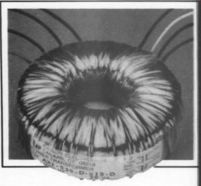
Toroidals require only 10 percent of the open circuit power required by laminated transformers, and are approximately half the weight and size of com parable laminated versions. Because the core is a single strip of steel wound in a doughnut, and because the primary and secondary winding completely envelop the core, audible 'hum’ is virtually nonexistent.
For complete details, contact Bicron Electronics Co., Barlow St., PO Box 807, Canaan, CT 06018, (203) 824-5125.
The growth of stereo television broad casting in the United States is being nurtured by a British company, Solid State Logic.
DB Systems has released a new 12dB in put attenuator, the DBP-16. When used properly, it solves the problem of sources which have too high a level, yet has no effect on distortion or frequency response.
For further details and ordering information, contact DB Systems, Main St., Rindge Ctr., NH 03461, (603) 899-5121.
Signet.
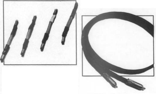
Each lead consists of 20 conductors of LC-OFC (linear-crystal oxygen-free cop per) wire. The large number of conductors increases the conducting surface area, resulting in significant reductions in high-frequency signal loss.
LC-OFC's high conductivity is due to its large, greatly-elongated crystals.
Because there are far fewer gaps for the signal to span, LC-OFC preserves the signal waveform better than comparable materials.
In 1982, the Oxford-based manufacturer introduced the SSL Stereo Video System, the first computer-assisted audio console specifically designed for stereo television soundtrack production.
The SSL system gives engineers precise control over as many as 128 different sound sources, adjusting the tone, loudness, and stereo position of each.
Tandberg has released a new series of matched audio transmission cables, designed as a result of research into advanced transmission-line theory, physics, and materials. The cables include such features as proprietary polyolefin insulation (believed to be the finest dielectric available), oxygen-free copper conductors, locking RCA-type phono connectors, electrically sym metrical and balanced conductor con figuration, low inductance construction to ensure amplifier stability and proper realization of the amplifier's inherent damping factor, low resistance to pre vent losses and for minimum interaction with speaker impedances, characteristic impedances chosen to ensure minimum electrical reflections, and integral rigidity to prevent lead movement within the speaker cables.
For complete details, contact Tandberg, Labriola Court, Armonk, NY 10504, (914) 273-9150.
After individual sounds are processed on the SSL system, they are combined into “groups ” or related sounds, which are in turn divided into stereo “sub mixes. ” For example, one sub-mix may contain speaking parts, another may contain music sections, and another may contain sound effects.
With the SSL system, engineers can quickly control the overall mix of dozens of individual sounds by using only a few sets of controls. The system also provides a built-in computer which controls every audio and video tape machine involved in the process.
Another part of the computer memorizes every level adjustment made by the engineer, allowing the soundtrack to be built up in sections. An additional SSL computer records the positions of all control panel knobs and switches (as many as 6,500) so that the process can be duplicated, if required, at a later date.
SSL's Stereo Video System has been installed at four NBC studios, while Turner Broadcasting System has equipped a mobile tele-production truck for stereo sports and special events coverage. In addition, ABC uses an SSL to put together the final soundtrack for ‘Wide World of Sports.' For more information on the SSL system, contact Doug Dickey, Solid State Logic, 2633 Fifteenth St. NW, Washington, DC 20009, (202) 797-0700.
Signet has also introduced two new LC-OFC audio cables. The SK481 audio interconnect cables are a two-cable set recommended for connecting CD and high-definition audio components.
Each cable is a five-layer composite.
Sheathing the conductive core is a polyethylene insulator jacket, which is covered by a second insulator of foamed polyethylene, a braided LC-OFC shield to eliminate stray RF emanations and interference from other electrical and electromagnetic fields, and an outer jacket of PVC.
The ultra-high conductivity of the LC OFC is because the linear crystals are larger than standard tough-pitch copper and oxygen-free copper. With fewer gaps, the SK481 is more conductive than conventional cables.
To learn more, contact Signet, 4701 Hudson Dr., Stow, OH 44224, (216) 688-9400.
LETTERS
CORRECTIONS:
DALZELL RELAYS
I CALL YOUR ATTENTION to two small errors in my article 'Using Solid State Relays ” (TAA 2/86).
First, on the last line on page 16 and the first line on page 17, the IC CD4071 should read CD4017.
Second, Fig. 8 on page 21 should be titled “The circuit board and stuffing guide for my sequencer. ” L. B. DALZELL El Cajon, CA 92020
SHEDDING LIGHT ON INTERFERENCE
With no chagrin, I must pass along a recent troubleshooting experience.
While checking out a new trans former, I detected a hum-a strange characteristic for a toroid. When it was on the bench, it even buzzed! The factory could not duplicate this curious behavior, however, and the designer suggested that DC in my house line (possibly from a TV) might be the culprit.
It took awhile to find, but the DC source proved to be “bulb savers” in a lighting fixture I had installed in my workshop. These widely advertised items extend the life of light bulbs by converting AC to DC. I installed the “bulb savers ” without carefully reading the literature, shortly before I obtained my “faulty” transformer.
My thanks to the Toroid Corporation of America for their timely help in solving this problem.
Ted WLBUR; McLean, VA 22101
I've READ THE ARTICLE by L.B. Dalzell on solid state relays (TAA 2/86), and found it very interesting and informative. It is the ultimate in switching AC loads.
Those readers who are not overly concerned about turn-on at the zero crossing point might want to try the Alco switch miniature induction relay, avail able from distributors such as Newark Electronics.
I've been using one to turn on my system for about ten years. I switch be tween three different power amplifiers, making my selection by turning a two deck wafer switch. It has worked reliably every time.
George ROBINSON Silver Spring, MD 20904
BOAK REWORKS PASS-A FOR LOW Z
IN THE AUDIO AMATEUR article Power Modifications for the ST-150-BJ-I (2/81), Mr. Boak indicated his willingness to help those of us who wanted to use his regulator in somewhat different applications. I would like to avail myself of his generous offer for my design of a fully regulated, dual mono version of the Pass Class-A amplifier.
I am using two 500VA 40 + 40V RMS I.L.P. toroidal transformers for the raw supply, with 10,000xF Sangamo reservoir caps. At the output of the regulator, I expect to use 6,000uF 40V caps suitably bypassed with film caps. The heatsinks I have chosen (actually, they chose me at the surplus shop!) are Wakefield 486s, two of which I believe should cool one channel and its associated pair of regulators.
In the interest of low output impedance and good thermal tracking be tween amp and regulator, I am going to try to mount each regulator in the larger central section of the respective sink.
Although I haven't figured out where the output caps will go, I feel fairly confident of the design to now.
Since each regulator pair will serve only one channel instead of two, I must choose a regulator transistor required to protect the amp's output transistors.
Which transistors should I use for this configuration? I hope to be driving a pair of low impedance ribbon midrange tweeter units (perhaps Strathearns), so the amp must be able to provide a reliable and healthy amount of current.
In the latest Old Colony catalog, the regulator entry states that Mr. Boak's 1/80 article describes the tradeoffs involved here. After a reread, I understand only that the regulator will allow the amp to pass more current. Perhaps what I really need is a clarification, and some assurance about how to use four regulators.
Mark HENSCHEL; Scarborough, Ontario MIR IH5
Mr. Boak replies:
The Strathearns, and in fact all the rib bon speaker designs I am familiar with, have a low impedance on the order of 0.50 or less. Normal power amps design ed to drive 8 ohm loads have a power sup ply and idle current designed to optimize operation at that level, and often do not drive low impedance loads well.
For example, a typical direct-coupled 100W amp will have + 45V rails, which will allow about 43V peak to appear across the load. This is equivalent to 30V RMS, which would provide about 110W RMS to the load, at an RMS cur rent of 3.75A, or 5.25A peak.
It is important to understand that such an amp is designed with the 80 load as an integral part of the design.
When the peak current of 5.25A is being delivered to the load, only 2V exists across the transistor, for a total dissipation of about 10W. The worst point on the transistor's operating curve actually occurs when the amp is delivering about three-fourths power, for then the transistor has about 50% of the supply voltage across it at about 50% of the peak current, for a total dissipation on the order of 40W. A good rule of thumb for a Class AB amp is that each output transistor will have to dissipate about 20% of the total power consumed by the amp. This is equivalent to about one third of the output power, or 33W maximum for a 100W amp.
If, however, the enterprising audiophile disturbs the assumptions on which the designer based his calculation, the situation becomes not so sanguine. Consider, for example, the case of a reactive load, say a high capacitive electrostatic speaker. The current required by the load will lead the voltage by a substantial margin, nearly 90% in a pure design.
The unfortunate output transistor will see the 5.25 peak current at a time when the full output voltage is across the transistor, for a peak dissipation of 240W.
Most 150W, 30A, 200V transistors will not go into secondary breakdown at these levels. The design tolerances, however, will certainly be exceeded, and the transistor will quickly overheat, even though the RMS power may be small.
To keep the transistor from being destroyed under these conditions, most recent designs incorporate a safe-area limit circuit. It limits the combination of current and voltage which can appear across an output device. The operation of these circuits is not usually musically pleasing, however, and the amplifier should never go into limiting when doing its job normally. This is why many amps which sound good driving loads, which are mostly resistive above 49, and which have adequate (in theory) power ratings to drive capacitive, inductive, or low-impedance loads, nevertheless sound gritty, metallic, or worse.
Needless to say, a half-ohm ribbon is going to look a lot like a short circuit to an amp designed for 80; the phase situation may be good or bad depending on the particular ribbon design. One solution is to employ an impedance matching transformer to boost the current out put of the conventional amp. Readers of TAA will be familiar with the many sonic disadvantages of this approach, even if we do not consider the reflected impedance problems. I will not belabor the undesirability of an additional trans former in the signal path. How, then, can you provide the high currents needed by the ribbon without throwing your power amp into a dangerous operating area! First, start with an inherently stable, high-current design with strong thermal performance. The Nelson Pass Class-A amp is an excellent choice, having the ability to provide 15A into a 12 load. An FET output stage might be an even better choice, due to the better resistance to overload damage. No design available at this writing, however, has the right combination of power and sonic desirability to match the Pass design.
If you know you are going to be driving a load of 12 or lower, you can further relieve the output power transistors.
Assuming you wish to deliver 15A RMS to the load (for about 100W at .5), you need only supply 7.5V RMS, due to the low value of load impedance. A 15V rail will provide this capability with a substantial margin, while reducing the dissipation requirements of the output stage by over 200W.
The amp runs cooler, is safer, and can still be vs. directly to the ribbon for the best coupling and dynamic control.
To provide this power, you really on ly need the + 25V version of the 500VA transformer. The caps you have selected are fine. The extra voltage margin will help to keep leakage low, which extends their life. The raw supply will develop about + 35V DC at no-load, about + 28V DC at full load. The regulators should be designed to provide 15V out at a peak current of 22A. The Pass amp, with some minor alterations, can easily sustain these values. If all of the components for each rail are mounted on a common heatsink, including the voltage Regulator IC, then the current available to the amp will be decreased should the output stage heat up for any reason. All of the components supplied with the Pass OC regulator kit are rugged enough to stand up to this application without difficulty, and the regulator should have no problems with this unusual, difficult load. Some minor changes to both the regulator and the Pass circuit are required to provide the results discussed above. The output stage will be powered by the large regulator; use smaller integrated-circuit regulators to provide a higher voltage to the driver section of the amp.
The amp design lends itself to this approach, as the output stage is separate from the circuit board. See Figure 10 of the 4/78 article, as revised. I have brought out the supply rails for the amp and supplied them with LM320T and LM340T regulators, providing + 24V to the driver section of the amp. Since the driver section is fed by constant current sources, this change should not cause any problems in operating parameters within the amp.
The output stage is then fed from the large regulators, which should be set up with 0.820 resistors for R5 rather than the 0.56 values supplied for the Pass configuration. You will also want to reduce the value of the zeners to provide an output voltage of 15V. Z4 should thus be about 10V, Z1 should be left at 27V, and Z2 can be replaced with a jumper to provide a fixed pre-regulator value of 25V. This will leave 10V across the main power transistor and R4 at no load, and 7V at full load, which is a safe value pro viding good margins for control.
Changes will need to be made inside the Pass circuit as well. Change R16, R17, R18, and R19 from 0.68/1W to 0.33/5W types. These provide degenerative feedback and also control idle cur rent. With the higher currents you are using, the original values will provide too much signal loss and will overheat.
This change should increase the idle cur rent, but verify that you have 1V be tween emitters of Q7 and Q9, adjusting R11 if necessary to achieve this value.
With this arrangement, the Pass amp can deliver 22A peak and 15A RMS into the .5Q Strathearn ribbon. There should be a 15A fuse in each supply rail. Idle current will be 3A, for an idle power of 90W. This compares with the 106W idle power of the amp as designed.
At full tilt, the revised amp will draw 225W, while delivering 110W to the load, for a total output-stage dissipation of around 115W. This small increase over the idle power is due both to the nature of the Class-A design and to the close match of supply power and load demand. The original 8Q2 version had a full-power draw of about 130W, while delivering 40W to the load, for a total output-stage dissipation of around 90W.
Each re or will have to dissipate 60W at idle, and 100W at full power.
This means that the total dissipation for the amp will be 210W at idle, and 425W at full power. The 486 heatsinks you have selected are capable of dissipating the idle power of 105W, each with a rise of 40°C B with no forced air cooling. The temperature rise at full power would be about 60W.
I suggest you employ a simple thermostatic switch to start a fan if the heat sink temperature exceeds 60°C (140°F), as these high temperatures could be dangerous to the long-term health of the output stage. In most circumstances, the amp will never exceed its idle (Class A) power, which means the sink fans should rarely run.
EXPERIMENT BEFORE SPEWING VENOM
When I Read the Colloms article in TAA 3/85, I expected it to act as a springboard for further intelligent discussion on the correlation (or lack thereof) between amplifier measurements and sound quality.
The amount of venom your letter writers expressed in their critiques sur ised me, and I can only suggest other readers who share these views should try their own experiments before dismissing Mr. Colloms' opinions as nonsense and attacking him in print.
To those readers who believe specifications tell the whole story, I recommend auditioning a modern bipolar amp, with its excellent specs, and comparing the sound quality to that of an old, respected tube amplifier with poorer specs, such as the Dynaco Stereo 70.
When I tried this test recently, I expected the Stereo 70 would be hopelessly outclassed by the solid-state amp. I was very surprised to find the ST-70 outperformed the newer amp in imaging and high-frequency transparency, and equaled it in every other respect.
Mr. Colloms (and others who share his views) may be on to something important. Their opinions deserve to be heard in TAA and discussed intelligently.
D. P. - Livonia, MI 48154
DISTRIBUTOR DELIGHT
GE has gone out of business, but there is good news. The L (TAA, 1/86, p. 10) has a new distributor: Active Electronics, 133 Flanders Rd., Westborough, MA 0158. (1-800-343-0874; 617-366-0500). The best news is Active's prices for the ILP items show no increase over Glad stone's. In fact, transformers are a few cents cheaper. Active's catalog is comprehensive, and contains virtually all other parts for my speed control device, including the EXAR 2206 chip.
Also, I have been using the Merrill turntable motor for quite some time, and I recommend it enthusiastically (Under ground Sound, 2125 Central Ave., Memphis, TN 38104). I can only echo Andy Catanzaro's comments in the letters column of TAA 3/85. The most apparent difference is in the dynamic range of the turntable. The impact and clarity on loud transients is literally incredible. Pitch stability, particularly on piano recordings, is noticeably improved.
Any AR turntable using a heavier platter mat will gain greater pitch stability from using this motor. Perfectionists who have built my AR mod (TAA 3/85) should note I consider this turntable 'complete' when used with the Merrill Vee and my speed control device (TAA 1/86).
The Merrill motor, incidentally, works beautifully with my speed control unit.
Only a very slight adjustment of P-3 (gain) is necessary to maintain voltage at 115V RMS.
Those of you who wish to try the Mer rill subchassis are encouraged to do so.
Do not, however, trim the tonearm boss to fit within the existing particle board cut-out. Instead, cut the particle board to accommodate the boss. Since I have not actually seen the Merrill subchassis, I do not know whether any further cutting in my top plate is necessary. (It should be noted the first motor I received from Merrill developed a knocking noise soon after I installed it. I spoke to George Mer rill on the phone about the problem, and he immediately sent me a replacement.
Mr. Merrill is extremely helpful, knowledgeable, and greatly concerned about customer satisfaction.) When used with my speed control, the Merrill motor will not turn at 78rpm. There is, however, a solution. With AR's 50Hz pulley in stalled on the motor, and the belt placed on the large (normally 45rpm) pulley, the turntable will run at 78rpm with the speed control dial set to around 5.9. If you do this trick with the 60Hz pulley, the speed control dial must be advanced to 8.0 to achieve 78rpm. The motor, however, runs a bit noisier at this frequency, so the 50Hz pulley is the best solution.
The suspension tuning problems I referred to in the TAA 3/85 article still re main, but serious 78 collectors will no doubt want a separate turntable dedicated strictly to 78 discs. The suspension on the 78 turntable could, therefore, be adjusted to accommodate the heavier records, without concern for LPs.
Unrelated to any of the above, builders of the superb Pass A-40 power amplifier may encounter a problem which I in tended to report a long time ago. The long lead lengths from the output transistors to the circuit board (inevitable due to the large heatsinks) may cause an oscillation. One channel of my Pass exhibited this oscillation at power levels above 12W RMS, raising the THD to 0.5%.
The solution is to add a power supply bypass capacitor from the case of each output transistor to chassis ground, i.e. the aluminum heatsink. (Be sure to scrape some of the black anodizing off the heatsink to ensure good connections from the caps to the heatsinks, and from the heatsinks to the chassis). I recommend a 224F electrolytic in parallel with a 0.1uF polypropylene. A total of eight are needed for a stereo amplifier. Needless to say, observe polarity on the electrolytics! Readers who believe the polypropylene bypass for the electrolytic is of no value can do one of two things: write a letter to the editor castigating me for advocating such lunacy (and the editor for printing it), or simply omit the policy cap and use the electrolytic unbypassed. I prefer the latter option.
Gary A. Galo; Potsdam, NY 13676
A SUBSCRIBER FOREVER
I'M WRITING THIS LETTER tO express my long overdue appreciation of your fine jour nals, Audio Amateur and Speaker Builder. I've been receiving each since their inception, and it just occurred to me that I've never given you any feed back to express my gratitude.
The time has come. I eagerly await the arrival of each of your publications. They fill the void be tween the artist and the technician; between the underground gurus and the advertiser-owned glossies. I've built or modified every component and interlink in my present system, almost always with favorable results. Sometimes, I've followed a systematic step-by-step process (such as the first pass to the past pass), but more often, I've used the applications offered by Amer, Borbely, Jung, Pass, Sulzer, Williamson, and many other excellent contributing editors who write for your journals. This information, presented in such an at tractive format, can be found in no other publication. It is for this reason that I will subscribe as long as you publish.
I don't feel this letter would be complete without an appreciative mention of Old Colony. 1 have ordered components from countless sources, and none of these can begin to compete with Old Colony's efficiency or quality of ser vice. Incidentally, while the Old Colony catalog #1 was an excellent move, ordering information for PC boards was omitted. Was this intentional? In closing, I have a couple of requests:
I'm sure you would agree that tubes still have a place in our endeavor for reproducing sound. (Indeed, much of the enjoyment I find in this hobby was sparked by a “Special Construction Issue” of Stereophile, 1966. Many have never heard of it.) Please continue to support these tube projects. The previously mentioned PAS series, the Audio Research ST-70-C3, the Waldron Crossover, and the Curcio Head Amp and Daniel Pre amp are excellent, comprehensible projects which have no reasonably d able commercial equivalents.
There are literally thousands of Dyna tube amplifiers still in use, begging for an updated modification from your tube loving contributing editors.
[…] “Showcase ” and “Classic Circuitry” departments. If the J.J. Curcio of Daniel preamp fame is the same Joseph Curcio of Paoli fame, perhaps he would allow Classic Circuitry to carry the Paoli 60m schematic. I'm sure many readers would be interested in the potential of the Dynaco Mk III.
Bob Roemer Rancho Cordova, CA 95670
Old Colony's face is red. The boards were unintentionally omitted. -Ed
HERE'S TO OLD FAITHFUL PASS A-40
Just A short NOTE TO alleviate a little guilt … long time. Work and family minimize time o tt EE you, however, I built the Pass A-40 power amplifier (TAA 4/78), and it has been faithfully and superbly driving my Magneplanars for more than five years. Immersing myself in this project was a joy eve aory.
I recently auditioned a Moscode 600 ($2000) and an Eagle 2 ($1000), and it ranked easily with these amplifiers and cost less than $400 to build. I would thoroughly enjoy a high-powered amp construction project (perhaps a tube/ mos-fet hybrid)
Nick SRN Northridge, CA 91325
JUST LOOKING FOR THE PRICE
I am bemused BUT pleased that you saw fit to publish Bob McIntyre's vacuum tube tutorial (TAA 2/86) for the benefit of the 'younger generation ” of TAA readers. I am surprised, however, that his list of references omitted what must certainly be the single most valuable work for DIYers interested in tubes: F. Langford-Smith, ed. Radiotron Designer's Handbook, 4th Ed. (Sydney, Australia: Amalgamated Wireless Valve Company Pty. Ltd.), 1953.
The book was reprinted and distributed in the United States by RCA Electronic Components ( Harrison, NJ) in May 1968. Although it has been out of print for many years, copies regularly show up in used book shops here in the San Francisco Bay area. The book is well worth seeking out not only for its wealth of detailed theoretical information, but also for the dozens of practical circuits it reprints, and especially for its voluminous chapter bibliographies covering much basic work done in the period from about 1930-1950. I cannot recommend it highly enough.
Definitely in the “not recommended ” category, as far as I'm concerned, is your “Just Looking ” feature, due to the absence of price information for all but one of the items described in the 2/86 issue.
I don't know how other readers feel, but I found this section to be of only margin al interest when you first introduced it some years ago. Without prices, I find it to be utterly useless. The blurbs are indistinguishable from (unpaid!) advertisements, so why not solicit payment from the manufacturers to help defray your publication costs? The 'fast reply' cards aren't much help either, since the manufacturer usually responds by sending a list of sales representatives, one of who I must then write or telephone to find out how much his gadget costs.
If your motive for publishing these announcements is to provide a service to readers, it doesn't provide very much ' “service ” when I merely desire an answer to the simple question: “how much does the product cost?. ” I'd much prefer that the space be devoted to another technical article.
Scott MAROVICH; East Palo Alto, CA 94303
Our regional postal service inspector advised us two years ago that prices in our new products section would require us to pay advertising rates for delivering those pages. (Second class postal rates are higher for ad pages than for editorial pages.) We have questioned the ruling, and are now advised that prices are admissable in editorial matter. In future manufacturer's suggested list prices will be included. -Ed.
IMPROVING CDs ON THE BEACH
I ENJOYED DON SPANGLER'S “Opinions ” in TAA (1/86, pp. 31-33), and am particularly interested in the comments on CDs and CD players. I live on the beach where disk records are prone to attract moisture, dust and sand. I got around some of this by using reel tapes and high quality cassettes. The CD, however, seems to be a more elegant solution. I have started by buying a Philips Magnavox 1040 CD player. I am particularly interested in the modifications Mr. Spangler made on his 2040, and I hope he can help me decide how or if I should try to improve my 1040.
Is the analog section of the 1040 the same as the 2040? What is different? Did he change absolutely all the resistors? Was replacing the “chip ” resistors with wire resistors difficult, or just tedious? The only electrolytic capacitor shown on the 1040 schematic is 22uF. My Old Colony parts list does not include any polycarbonate film capacitors of 22uF.
Any suggestions? I assume the power supply he made for his 2040 was installed outside the 2040.
Is it worthwhile for me to do the other modifications without doing anything to the existing power supply except removing the 100 ohm resistor?
Paul Foster, Wilmington, NC 28405
[The referenced schematic is not included here since readers who make these mods will have their schematic to refer to-Ed.| Mr. Spangler replies:
I am pleased to help you with the project of modifying your model 1040. Actually, the circuit from the digital filter through the analog output is essentially the same in the 1040, 2040, and 3040.
Some use surface-mounted components, some use conventional.
Walt Jung and I have spent consider able time with this CD player series, and feel we have produced a CD player which far exceeds the sound in the already-fine unmodified units.
The modifications go far beyond the ones described in my article.
To answer your questions, I changed the resistors from the output of the digital-to-analog circuit to the output jacks. In other words, the analog circuits.
On my conventional unit, these were simple to replace with Corning resistors.
This job, however, will be a more difficult one with units using surface mounted components. You might skip this modification if you do not want to tackle a rather difficult task.
The surface mount resistors may not sound the best, but neither will they excessively degrade the sound.
The op amp change is very important.
Try the TL072 integrated circuits as a direct replacement for the 5532. The capacitor at positions 2573 and 2608 ... […] , 1631 Caledonia St., La Crosse, WI 54602
...should be able to supply.
If you do not want an outboard power supply for the analog circuits, I suggest you short across resistors 3582, 3583, 3596, and 3599. Remove capacitors 2617, 2618, and 2619.
Install a 0.1uF polypropylene from pin 8 and pin 4 to ground on each op-amp.
Change capacitor 2627 and 2624 to a low ESR 100uF capacity.
SAYING IT SIMPLY
Regarding THE REGULATOR (TAA 1/86, p. 56) by Mr. Hurley, I don't have copies of the old issues to refer to the various approaches which may have been taken to solve the regulator problem, but the schematic strikes me as very verbose. I looked around to see if there was an unusually elegant answer to this design problem.
have enclosed an application circuit Sam Ga aril Tahiti. This seemingly too simple circuit does it all, and without a hassle. To adapt it to the Hurley application, you must block about 120V when supplying current (for the output Tr.). Since the Hurley breaks this job down into two TIP 50s, perhaps there is no adequately safe area for the application.
High Voltage Regulator
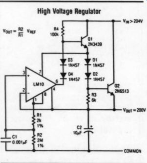
The MJE 8502 will supply about four times the current of the TIP, if this is required. Then, use the MNJE for Q2. The TIP 50 will work in place of the 2N3439, which may be required if the MJE is asked to supply 100mA or more. (This 700V part has very low beta.) To adjust the output voltage, simply set R2 to a value in megohms, which times 100 will become output volts. R2 equals 2.7 M-OHM, giving an output of 270V.
The LM10 contains two op amps, and a 200mV reference. All of these -- blissfully on a floating supply three diode drops. Lc nd phd photoflash caps, or any paraphernalia. The 10g capacitor is available in 350V size from Rubycon.
The on-off failure problem does not happen here either, because when the output device C-B junction becomes for ward biased, D1, D2, and the pin 7-4 bulk substrate diode all turn on and discharge C2. No heavy caps should be needed to filter the output, since the LM10 drives a cascade of outputs (effectively Darlington), and it also floats in a sort of regulator.
The internal reference is ultra stiff, and has super low TC. Expect exemplary performance in the area of a couple of thumb prints (sans pass device heatsinking, if substantial).
Even R4 can be AW, conservatively.
David Gore; Orange, CA 92667
To adapt this simple circuit to the Hurley application, change Q1 and Q2 to TIP50, R2 to 2.7M for 270V.
IN457 =IN914
Merrill Mods
I was interested TO read Dave Davenport's “Merrill Mod” review in TAA 1/86, p. 41, since I just finished modifying an early two-motor AR XA.
Because the two-motor design is obsolete, I ordered the Merrill motor in addition to the new subchassis, springs, spindle, platter lead-coating and balancing. Like Mr. Davenport, I installed a Linn LVX tonearm. I chose it because I already use the LVX on my ( Valhalla upgraded) Linn turntable. I thought by using the same arm I would compare the two units. I already had a suitable drive pulley for the single-motor design.
I found that the new motor must be located about one-half inch closer to the spindle than the old main drive motor otherwise the larger drive pulley used with the single motor will foul the in ner edge of the outer platter. I also found it necessary to reduce the 0.047uF capacitor across the power switch to about 0.02uF to avoid excessive motor vibration when the switch is in the off position.
I found that the top of the LVX counter-weight would clear the dustcover by lowering the subchassis so that the tonearm mounting surface is somewhat below the level of the top plate. How ever, the front of the cartridge still will not clear the cover. For now, I simply swing the arm out over the turntable when using the dustcover.
With both the AR/Merrill and the Linn having the same arm, switching cartridges between the two tables is quite easy. A friend and I made extensive listening comparisons using the Shure Ultra 500, Shure V15-VMR and Dynavector DV-100R cartridges. AR felt mats were used on both turntables. We heard no hum from the Merrill motor.
Our results showed that the Linn and the AR/Merrill were very close in overall sound. The AR/Merrill, we think, was slightly more detailed, but slightly leaner-sounding than the Linn.
The Linn sounded slightly warmer and more “romantic.” Overall, I think I prefer the Linn, but the AR/Merrill is very good and, in fact, it may actually be reproducing more accurately. I could live with either unit.
I agree that the Merrill mods produce an excellent turntable for a very reason able price. And you have the fun, and the satisfaction, of doing the conversion yourself.
Tom SHEDD Wilmette, IL 60091
EXPLORING BORBELY’S SECOND STAGE
I'm seriously considering to build Erno Borbely's preamp from TAA (4/85, 1/86) articles, but I have a question regarding the second stage RIAA.
Even though he says the second stage isn't as critical as the first, couldn't I still use the first stage design with the second-stage feedback network for the resultant second-stage? Judging from the articles, this would seem to work.
Regarding the tape buffer: could the phono FETs be used without major component changes? Any advice would be appreciated.
WAYNE J. MASTEL Lincoln, ND 58501
Mr. Borbely replies:
Regarding your first question, I have considered this possibility myself, but decided against it due to the relatively high DC-gain of the RIAA-2. (DC-gain is 34dB, which equals 50x). This would require a fairly well-balanced input stage, otherwise you might run into off set problems.
If you would like to try it, I suggest you use matched input FETs, or at least use FETs from the same IDSS group.
The best choice is the BL-group.
In addition, you can add a trimpot to the source circuit (Fig. 1) to trim out initial offset. The servo will then easily cope with the temperature variations in the amplifier.
Adding the second stage feedback net work to this circuit will, most likely, change the stability of the amplifier. It is, therefore, essential to check and optimize the stability for this feedback network.
A word of caution: the RIAA-1 circuit has an excellent noise performance with low impedance sources, but has practically no advantage with high impedance versions. To truly optimize the circuit for an RIAA-2 amplifier, you would have to down-scale the feedback network and the 75uSec RC-rolloff in the first stage. This represents a major redesign of the amplifier.
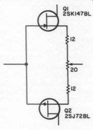
Regarding your second question, yes, you can use the phono FETs in the tape buffer. The input capacitance will be higher, but it doesn't represent a disadvantage in this application. By the way, resistor R2 should be 221 ohm, as stated in the component list, and not 22.10 as shown in the schematic.
'LEADEN’ EARS
OVER THE YEARS (I'm pushing 67), my “golden ” ears have turned to lead.
Various tests have confirmed what my wife has been telling me for much too long: I can't hear so good no more. Important middle-range frequencies are down 30 to 40dB, and the high end above 10kHz is gone. Coupled with this sad state of affairs is a dramatic loss of dynamic range. Compact disks, Beta HiFi, digital recordings and live programs, with their 80 to 90dB of dynamic range, are all lost on me. I can hear the pianissimo, and the fortissimo hurts. All this leaves me with the blandness of Muzak.
I now listen via headphones, as my family complains when I crank up the Crown DC-300 to levels I can hear.
With the headphones, the sound is “immediate.” The highs are present and clear, while the bass does not shake the floor, but is at least present. I can adjust the volume below the threshold of pain and still hear most, if not all, of the soft passages.
I am probably not the only subscriber to have this problem. Although TAA is directed primarily to those fortunate enough to have full possession of their hearing ability, I would like to see some information on headsets, image enhancers, equalizers and other signal processing circuits. Some sort of “up ward compressor' (a reverse of the dbx “downward expansion ”) to bring up the soft passages without leveling off the peaks should help.
I am currently using a Technics SA-410 receiver as my headphone amp.
This is fed with a Technics SL-5 turn table system and a Hitachi D-RV7 cassette deck. A BSR EQ-110X equalizer is in the audio chain to help the head phones match my ears' deficiencies.
This is by no means the greatest system, but superlative equipment is essentially meaningless to one whose hearing is impaired.
Frank C. SMITH Gig Harbor, WA 98335
I built a turntable from scratch and hope some of the things I found out will be of value to those who want to restore or construct one.
First, it is difficult to filter out the 60Hz motor vibrations completely.
Vibrations due to unbalanced armatures are no problem if you use a low-speed motor such as a 300 rpm one. I constructed mine with such a motor suspended on three coil springs.
I used a low-torque, 300 rpm synchronous motor similar to the one AR uses in its new turntable and a belt removed from a BIC turntable. In spite of the high-quality belt, a slight amount of vibration at 60Hz was coupled to the platter through the belt. The same seems to be true with my new AR. In an old Thorens (combination rim and belt drive) and an old Pioneer PL15, most of the coupling seems to be through the motor-motorboard-platter link.
You can simplify Mr. Markwalter’s design and reduce the cost by eliminating the idler assembly. Most belts will stretch enough for the 33 to 45 speed change. Perhaps the motor mount would have to be slotted or pivoted to accommodate the 78 speed (if wanted). Also, if you crown the pulley steps, the belt will remain centered on the step. This will eliminate fraying due to contact with the idlers and pulley steps.
My major criticism of his design is the motor mount. I have repaired several audio-visual items using motor suspensions similar to that described in his article. After an indeterminate time, the rubber suspension com presses and/or decomposes and the motor cocks on its mount. A much bet ter approach would be to use three or more compression springs. If chosen correctly, they will supply sufficient lateral force and provide better vibration isolation.
If you use a low-torque, 300Hz synchronous motor, the pulley will be large enough to machine easily and the belt will not have to turn around such a small radius. These small motors are inexpensive (less than $5) and have little vibration. Of course, they do not have enough torque to rotate heavy cleaning brushes.
One easy way to determine whether a turntable is quiet enough is to use a stethoscope with a diaphragm about the size of a half dollar. Hold it on places such as the end of the tonearm and the pivot region. If the tonearm has any vibrations coupled to it, they will be audible. By orienting the diaphragm in different planes, you can get an idea of whether the vibration is largely horizontal or vertical in origin. The easiest way to hear turntable noise is to hold a pin between the diaphragm and the top of the record spindle. This will allow you to hear noise that is inaudible even when playing quiet grooves of test records. If I were going to build or modify a piece of equipment using a belt drive, I would consider using a small, DC-speed-regulated motor similar to those used in some tape recorders.
GEORGE SHELLENBERGER Clarksville, AR 72830
ADs ...
RACK MOUNT CASES
High quality at reasonable prices
Easy to work with
Ideal for audio equipment and test instruments.
Anodized aluminum front panel and handles. Black painted and perforated steel top plates and side panels. Interior mounting panel for control pots.
FAST DELIVERY ANY IN U.S.A.
Each rack mount case kit contains one aluminum front panel, one steel interior mounting panel, two steel side panels, two steel covers, two aluminum handles, four rubber legs, one bag of assembly screws and an assembly diagram.
US MAIL ORDERS: Call our agent in Dallas on VISA/MASTER CARD orders, or send check, money order to PO Box 863, 537 Plano, TX 75086. Add $5.00 for shipping and handling.
578 Mariee Ave., Toronto, Ont. Canada SUNIX, INC. Tel. (416) 781-3263. In U.S. (214) 985-1842.
============
105ANOTC? KP-49C SUPER CLEAN HEADPHONE AMP Two Channels for only $128! (NOW IN STOCK AGAIN)
Designed by Jim Boak
Can be optimized for either electrostatic or dynamic phones
Direct coupled, using a 540 op amp
Class A operation
Low noise and distortion
High slew rate
Extended overload capacity gives you a clean, wide open tube-like sound
Well regulated power supply, independent for each channel The headphone output on most amps usually is a large resistor in series with the output to knock the level down to what is suitable for driving headphones. The resistor reduces the amp's damping ability, leaving your headphone drivers less tightly controlled. You will also suffer the distortions produced by the resistor's particular nonlinearities. To solve these problems, Jim Boak has designed a high performance amp specifically for headphones. Built around the powerful 540 op amp, it features a circuit modification, derived from Walt Jung's work, which gives the op amp a highly linear transfer insulting distortion curve has that gentle rise associated with good tube amps, and a clean, wide open sound quality you will enjoy thoroughly every time you listen on headphones. To top it off, Boak gave it excellent power supply regulation.
Each channel has independent power supplies using three terminal regulators to deliver stable voltages across the en tire audio range. The amp may be configured for driving either electrostatic or dynamic headphones, and parts for both are included. (The 540 included is the older version, voltage limit 24V. QUANTITIES VERY LIMITEDY)
KP-9 TANGENTIAL TRACKING TONE ARM
Only $160! Here's your opportunity to own a tangential tracking tone arm-and have the fun of building it yourself.
Rod Cooper's ingeniously simple design elegantly achieves the benefits long attributed to tangential arms. The kit has been sold in England for several years and has been praised for its high quality. The metal parts are precision-machined for a solid, tight-fitting assembly. Mount it on your choice of turn tables, and you will have an outstanding piece of equipment which you can use and enjoy every day, for many years of listening enjoyment.
Improved tracking ability lowers distortion
Maintains tangency + 0.2°
low mass (10g) tracking arm of rigid Dural
Servo controlled, with opto-electronic feedback
Low friction gimbal suspension
SBK-C2 PHASE-ALIGNED ELECTRONIC CROSSOVER
Two channels for only $134 One of the problems introduced by crossovers is the phase delay they cause. Over the years, many attempts to minimize this problem have been made. Bob Ballard's solution starts with a simple method of measuring the drivers' phase relationships in the air. Then he shows you how to build a crossover with phase adjusting circuits and tells you how to put your system in alignment, from the preamp out puts to the sound in the air.
Three-way active crossover
Phase shifting circuits to fine tune your system
Easy method to measure actual acoustic phase relation ships among drivers
Op amp filters simplify design
Rumble filter built in
METAL FILM 10¢ each in quantities less than Old Colony is closing out its entire stock of Draloric metal film resistors. Take advantage of this opportunity to stock up at bargain prices. These precision audio grade resistors are made by Telefunken to exacting standards. They have tight specs at a high level of performance with long term reliability and stability-all to assure you of high fidelity in the audio equipment you build.
Extremely low noise:
less than .05 micro-V/V to 10k less than 1 micro-V/V to 100k less than 25 micro-V/V to 1 Meg Temperature Coefficient: 50 ppm/C° RESISTORS 100, 8¢ each for 100 or more
Tolerance: less than 1%
Maximum Power: 0.35W @ 70°C derated linearly to 0W
@ 165°C
* Maximum Voltage: 250V
Copper leads coated with eutectic solder
* All standard Old Colony E24 values are available except:
10, 20, 47.5, 68.1, 100, 121, 150, 182, 200, 221, 274, 2.21k, 3.92k, 4.75k, 5.11k, 6.81k, 8.25k, 12.1k, 18.2k, 22.1k, 24.3k, 27.4k, 39.2k, 43.2k, 47.5k, 56.2k, 68.1k, 82.5k and 150k.
Minimum Order: 10 per value.
=================
BOOKS from Old Colony Sound Lab S$-4B
TRANSISTOR FUNDAMENTALS: Vol. 2. Basic Transistor Circuits by Charles A. Pike. Describes transistors and how they are used in semiconductor circuits. Uses simple circuits to illustrate the basic principles involved and more complicated ones to show how the basic operations are applied. 208pp. Each $8.95
REGULATED POWER SUPPLIES by Irving M. Gottlieb.
Static and dynamic characteristics, regulation techniques, IC regulation. 424pp., softbound. Each $19.95
$-10 IC OP AMP COOKBOOK [3ro Ep. by Walter G. Jung. Jung's popular classic in a revised and expanded 1986 edition. One hundred pages are added to cover new devices, applications and manufacturer's data sheets. With over two hundred practical circuits with component values, this cookbook is one of Old Colony's best selling technical volumes. It belongs on every electronics bookshelf. 580 pp., softbound.
Each $21.95
HOW TO BUILD SPEAKER ENCLOSURES by Alexis Badmaieff and Don Davis. The ‘whys’ and 'hows' of er enclosures. Drawings and instructions cover infinite baffle, bass reflex, and horn types plus combinations. 144pp., softbound. Each $6.95
MODERN DICTIONARY OF ELECTRONICS [6m: Ep] by Rudolph Graf. This book should be in every library. It has more than 20,000 terms unique to electronics and other closely related fields.
From angstrom to zoom lens, you'll find it in this updated dictionary.
1984, 1152pp., hardbound. Each $39.95 MICROPROCESSOR CIRCUITS [1st Ep.| by Ed Noll, W3FQJ. Volume 1 presents basic concepts and fundamental circuits of microprocessor systems. Volume 2 presents microprocessor I/O circuits and programmable controllers. Each volume is written and edited in an un complicated manner. Both books, 1983.
$-23 Vol. 1: Fundamentals & Microcontrollers. Each $9.95
$-24 Vol. 2: 1/0 Interfacing and Programmable Controllers Each $9.95
$-25 ELECTRONIC PROTOTYPE CONSTRUCTION [1st Ep]
by Stephen D. Kasten. Here's a great book for either the beginner looking to try electronic prototyping for the first time or the expert looking for a handy reference guide. Areas covered include wire wrap and related techniques such as solder pad and perfboard assembly. This book will help you through all the pitfalls of PC board design, and will help you put the project together in an attractive but functional package. 1983, 399pp., softbound. Each $17.95
CMOS COOKBOOK [1st Ep.| by Don Lancaster. CMOS is low cost and widely available, and it uses an absolute minimum of power.
It's also fun to work with and very easy to use. This book offers practical circuits and does not dwell on math or heavy theory. Eight chapters cover just about every aspect of CMOS usage. Projects include high performance op amps, TV typewriter, digital instruments, music synthesizers and video games. 1977, 414pp., softbound. Each $14.95
SOUND SYSTEM ENGINEERING by Don and Carolyn Davis. A thorough introduction to sound systems for halls, studios, outdoor locations and much else. 245pp., softbound, 84x11. Each $24.95
DESIGN OF OP AMP CIRCUITS (1st Ed). by Howard Berlin, W3HB. Op amps are a versatile and inexpensive integrated circuit.
They can be used for linear amplifiers, differentiators, integrators, voltage and current converters, comparators, rectifiers, oscillators and more. The text includes 37 different uses and applications for op amps.
Beginners will find this book helpful. 1977, 221pp., softbound.
Each $11.95
TTL COOKBOOK by Don Lancaster. Everything the beginner will need to know about transistor logic elements and usage. It has be come a reference guide for engineers as well. Softbound. Each $12.95
ACTIVE FILTER COOKBOOK by Don Lancaster. A practical, user-centered volume with everything you need to build your own active filters. Explains the various types and how to select the best for the circuit. 240pp., softbound. Each $14.95 PRENTICE-HALL PH-1 HANDBOOK OF SIMPLIFIED SOLID-STATE CIRCUIT DESIGN [2nd Ed.) by John Lenk. Design rules for basic circuitry including audio amps, integrated circuits, wave forming and shaping plus power supplies. Assumes basic theoretical base. Discusses purposes and types of testing. Each $27.95
REPRODUCTION OF SOUND by Edgar Villchur. An elegantly simple 92-page softbound primer on the subject by the man who in vented the bookshelf speaker. Loan or give it to friends who want to build a system as good as yours. Each $6.00
MUSIC, PHYSICS AND ENGINEERING by Harry F. Olson. A thorough introduction to the physical characteristics of sound and the relationship of sound to musical instruments by the former head of staff at RCA's lab for acoustical and electromechanical research at Princeton, NJ. A classic by one of the giants in the audio field. Good, easy to read chapters on acoustics, mikes and recording, recording and playback systems, as well as an electronic music chapter. 1967, 460pp., softbound. Each $14.25 MCGRAW-HILL MH-1
HANDBOOK FOR ELECTRONICS ENGINEERING TECHNI CIANS (2nd Ep.) by M. Kaufman and A.H. Seidman. A comprehensive compendium of electronic facts. Component selection, circuit analysis, power supplies, IC uses and characteristics, op amps, transistors, batteries and tubes. A one-volume encyclopedia on how components work and how to choose the best of them for your application. Includes seven new chapters on topics such as logic analysis, fiber optics, active filters, digital test gear and microprocessors. 752pp., hardbound.
Each $39.50 MH-2 HOW TO MAKE PRINTED CIRCUIT BOARDS by Joel Goldberg. All the topics on making your own circuit boards are covered both in theory and in practical advice: design and layout, artwork preparation, photo layout, silk screening, and etching. Each $7.95 MH-3 LEARNING ELECTRICITY AND ELECTRONICS THROUGH EXPERIMENTS by |. A. 'Sam' Wilson and Milton Kaufman. Using four perfboards and typical 'junk box; parts, this book demonstrates theoretical principles in 54 circuits you can build as you learn.
Each $9.10
TAB BOOKS T-5 IC VOLTAGE REGULATOR SOURCEBOOK WITH EX PERIMENTS by Vaughn Martin. This sourcebook provides the knowledge needed to fully understand, design and service modern power supplies. It introduces the components found in all power supply designs, transformers, diodes and capacitors as well as concepts like AC, DC and filtering. The book covers bipolar and MOS transistors, ICs used in regulators, switch mode designs and output indicators.
Diagrams, data sheets and illustrations. 256pp., softbound.
Each $10.95 NATIONAL SEMICONDUCTOR -- N-2 LINEAR DATABOOK. This is National's biggest, most comprehensive collection of specifications and applications. Topics covered, with example circuits, include voltage regulators, references and comparators;
op amps and buffers; instrumentation amps; analog switches; sample and hold; A/D and D/A; automotive, industrial, and telecommunications devices; audio, radio, TV circuits; transistor/diode arrays; and speech synthesis. 1982 Edition. 1,950pp., softbound. Please add $1.50 for shipping. Each $12.00 N-4 TRANSISTOR DATABOOK. This handy reference book provides data for the physical and electrical parameters of all their transistors.
559pp., softbound. Please add $1.50 for shipping. Each $6.00 N-5 VOLTAGE REGULATOR HANDBOOK. A manual which simplifies selection of three-terminal regulators depending on your needs, and which offers information on heatsink selection and design, along with transformer and filter specifications. 312pp., softbound. Each $7.00 Hardbound. Each $29.95 The PENGUINS P-1 THE NEW PENGUIN STEREO RECORD & CASSETTE GUIDE (3&0 Ep.) by Edward Greenfield, Robert Layton, and Ivan March. Drawing on profound technical knowledge and on vast musical and historical learning, this newly revised and updated guide to recorded classical music deals with more than 4,000 disks, cassettes and compact disks, giving details of title, performers, record number, label and price range.
1387pp., softbound. Please add $1.00 for shipping. Each $12.95 P-2 A NEW DICTIONARY OF ELECTRONICS by E. C. Young. This remarkably compact reference covers electronics from A-Battery to Z parameters with succinct, concise definitions and illustrations. A quick reference completely revised and updated with lots of added charts and reference data. 618pp., softbound. Each $5.95 P-3 ANEW DICTIONARY OF MUSIC [3ro Ep., 1973; first pub. 1958] by Arthur Jacobs. Alphabetically arranged entries covering composers, individual musical works, orchestras, performers, conductors, musical instruments, and technical terms. 458pp., softbound. Each $5.95 P-8 INTRODUCING MUSIC by Otto Karolyi. Even if you've listened to music for years, you may be surprised at how little you know about its fundamentals. A beautifully basic and spare introduction to the grammar and vocabulary of music-enough to understand the language without speaking it. It will deepen almost any non-musician music lover's pleasure in listening. 174pp., softbound. Each $4.95
-To order from Old Colony Sound Lab, please write each book's number below with quantity of each and price. Total the amounts and remit by check, money order, Mastercard, or Visa. For charge card orders under $10 add $2 service charge. Please add $1 for postage on the first book; 50C per additional book. Orders shipped outside the US please add 15% for postage. All remittances must be in U.S. funds. Please use clear block capitals. NOTE: Prices are subject to change without notice.
==============
ALPS
With much of the quality of your audio project depending on its controls, can you afford less than the best? The tactile interface between electronics and listener should feel smooth yet solid. This aesthetic blend of quality sound and quality feel is engineered into a quality line of stereo potentiometers. Because of manufacturing and distribution volume requirements controls such as these have been difficult for the individual to obtain. Old Colony Sound Lab, through a special purchase, is able to offer the builder of quality audio equipment the finest in rotary controls-Alps.
The VR-20KB is a stereo volume control without steps or detent. Its full resistance is 20 k-ohm per section, dual section. The taper is logarithmic (audio). Tracking error is less than 1.5dB from 0 to - 60dB. The case is 34 x 33.5 x 40mm. The shaft is 1/8 “ long, flatted and accepts standard ( 1/8 “) knobs. Full rotation is 315° + 3°.
Mounting hardware is included with the control.
Ppd. Each $27.00 NEW The VR-250KB is a dual 250k volume control with 41 detents. It is ideal for use in tube-type preamplifiers and especially for all Dynaco PAS pre amps. Its two sections are matched within + 2dB from 0 to 70dB assuring excellent tracking. (The taper is identical to the one shown for the VR-20KB.) Size: body 25 x 25.3 x 27mm (HxWxD) (lugs project 5mm above Ht. measure). Shaft length is 13mm beyond mtg. bushing. 300° shaft rotation + 3°, accepts standard 1/4 knobs. Mounting hardware included. Ppd. Each $27.00 The VR10OKB is a stereo volume control. It has logarithmic taper, 100k{2, with 41 detents. Tracking error is less than 2dB from 0 to - 70dB. Case size is 25 x 25.3 x 27mm HDW. Shaft length is 1/4 “ beyond mounting bushing. Full shaft rotation is 300° + 3°. This control accepts standard 1/4 “ knobs. Mounting hard ware is included. (Same taper as VR20KB) Ppd. Each $27.00
The VR100KD is a stereo balance control. The sections are M and N tapered. A single detent is provided at the center of the 300° + 3° rotation. Tracking error is less than 2dB, from 0 to -70dB. The case is 25x 25.3 x 27mm HDW. The 0.5 “ long shaft accepts standard knobs. Mounting hardware is included. Ppd. Each $27.00
================
MODEL A-1033 This Integrated Tube amp is winning wide acclaims from kit-building audiophiles all over Japan. Superior performance achieved by:
1. Handcrafted output transformer that is virtually distortionless within its power rating, due to special winding techniques which result in widest frequency response and minimum phase shift.
2. Latest Japanese design with choice of UL (Ultra Linear) or Triode Output (for Class-A like performance).
3. Hum-free PCB layout for both preamp and power amp.
4. High quality components and instrument-like construction techniques.
KIT ONLY
Tube Compliment:
$449.00 SPECIFICATIONS 6CA7(4), 12AU7(2), 6AQ8(1), 12AX7(4) 30W x 2(40, 804, 25W x 2(16Q).
Both channels driven.
15W x 2(40, 80), 11W x 2(160).
Both channels driven.
Below 0.4% (80, 1kHz, 30W) Below 1% (82, 30W, 60kHz:7kHz =4:1) 30. ”.30,000Hz (w/in -1dB, 80, 1W) Phono: 2.2mV, TUNER AUX, Monitor -1, 2;190mV
Phono: 72dB, TUNER AUX, Monitor -1, 2;92db Call (415) 873-3055 for UPS charge to your area Power Output (UL Mode) (Triode Mode) THD:
Intermodulation Distortion Frequency Response Input Sensitivity SN Ratio (1HF-A weighted)
- MONARCHY INTERNATIONAL INC., P.0. Box 5517, 380 Swift Avenue, Unit 21, South San Francisco, CA 94080
================
GSI
Don't you deserve to own “The Best ” The GSI X-1! The X-1 employs computer de signed purely passive filtering and phase correction, combined with the latest bi-fet op-amps. It exceptionally clean with excellent resolution features excellent sonics and a Dick Olsher perfect square wave with outputs Stereophile Vol. 8 # summed. Options include summed bass, all gold jacks, passive hi end. All outputs have level controls, all 1% parts throughout, fully regulated supply, al DC coupled. A Brian Clark design.
PHASE CORRECT ELECTRONIC CROSSOVERS
X-1 2-way Kit $185 Assembled $250.
X-1 3-way Kit $250 Assembled $300.
This is easily the finest electronic crossover I've heard being
==============
DYNAMIC ACOUSTICS OFFERS PARTS We have, for a number of years, been a major supplier to the high-end audio industry in the United States.
We have sourced the most unusual and most sought after components, and we have made them available from stock. We offer a complete components program, and this is now available to you! We feature an extensive program of exceptional polypropylene capacitors from 0.47 mfd through 10.0 mfd values. These devices are of nearly non-measurable ESR and DF factors! In addition we offer a full pro gram of superb non-polar electrolytic capacitors from 4.7 mfd through 100 mfd values. These have been reported to us as being the most “musical ” electrolytics in the industry! This is certainly a critical factor when constructing a crossover network! Precision inductors (chokes) are our specialty. We offer ferrite bobbin core devices through 19.0 Mh with negligible DC Resistance and compact sizes for easy mounting. For those who insist upon air core units, we do wind those to 10.0 Mh. We can give you the precise values you require! We offer a full program of L-Pads, L.E.D.'s, 5-way binding posts, rear terminals, resistors, and more! Occasionally we offer closeouts at exceptional savings.
Our car stereo program is superb, and is available in a wide range of polypropylene drivers from 4 ” through 10 ”.
Who could ask for anything more? Don't delay. Write to us now for complete details and catalogs. You'll be glad you did.
Enclosed is $2.00 Please send complete info to:
NAME ADDRESS CITY OUR CONCERN IS A SOUND COMPANY P.O. Box 846 * San Ramon, CA 94583 * (415) 866-9500 STATE (03/86)
===================
NEW FROM OLD COLONY
Many customers have asked Old Colony to make five of the six assemblies of the Borbely KT-2 Preamp [TAA 4/85, 1/86] available separately for use in other projects. The Borbely design is, according to some industry observers, unique. Four commercial units of comparable quality are all priced above $3000.
Many of them are not available in the US electronic market. Every effort has been made to include the highest quality parts available and no expense has been spared to insure that this project will provide the builder with the best preamplifier which can be constructed from a kit.
PHONO EQUALIZATION STAGE 1-RIAA-1 (Assembly 4) is the analog phono input stage and half the equalization components. Designed to work with RIAA-2.
Each two channel kit $128 PHONO EQUALIZATION STAGE 2-RIAA-2 (Assembly 3) is the second half of the phono amplifier and includes the second half of the equalization components, active circuitry, and on-board regulators for the power. Designed to be used with RIAA-1 as a unique approach to analog record amplification and equalization. Each two channel kit $280
THE HIGH LEVEL LINE AMPLIFIER (Assembly 5) This output stage of the unit can be used as the main control amplifier for handling all inputs. Idea for a new system which omits the phono stage entirely, utilizing a Compact Disk player and other high-level output devices as signal sources. Does NOT include either the selector switch, or the volume or balance pots.
Each two channel kit $212 THE POWER SUPPLY (Assembly Two) is an excellent design and made of extremely high quality parts and could serve in any device needing clean regulated power of +24V DC sup plies for each channel. Regulators, rectifier bridges and filters on two 4 x 5 ” etched circuit boards.
Each two channel kit $88
THE TAPE BUFFER (Assembly 1) makes a fine buffer for any project where isolation is needed.
Two channels on two boards, all parts. Each stereo kit $48 Between August 1-September 28, 1986 The following discounts will be in effect on Borbely Assemblies available to current subscribers of Audio Amateur, Speaker Builder and Computer Smyth (All orders must include the MAGIC number of the subscriber.)
$48 - $149
DISCOUNTS:
$150 - $299
$300 – up
ORDER BLANK OLD COLONY SOUND LAB
P.O. Box 243, Peterborough NH 03458
Phone Orders MC/Visa only: (603) 924-6371
Item RIAA-1 STAGE, two chan. @ $128 ea.
RIAA-2 STAGE, two chan. @ $280 ea.
HIGH LEVEL LINE AMP, two chan. @ $212 ea.
POWER SUPPLY, two chan. @ $88 ea.
TAPE BUFFER, two chan. @ $48 ea.
10% discount 15% discount 20% discount
==================
JAPANESE
SEMICONDUCT/ TRANSISTORS
ICs
TOSHIBA HITACHI FUJITSU MATSUSHITA MITSUBISHI SANYO SONY NEC SGS
For Free Catalog Call or Write:
AUDIOLAB 5269 Buford Highwa Atlanta, GA 30340 (404) 455-0572
==============
----
Also see:
OP-AMP MEETS CD-- OIL & WATER OR MUSICAL SYNERGISM?