- Intro
- GUEST EDITORIAL--dbx Stereo-A Tempest in a Trimpot
- AUDIO AIDS
- JUST LOOKING
- LETTERS
-------
Intro
Starting us off this issue, Michael Swartzendruber offers a differential audio project in “Build the Balanced-Jack”. The author describes how you can use separate assemblies to convert an unbalanced audio system to one that uses differential connections.
Ken Miller re-counts how he removed the stock amplifier circuit boards and associated wiring from his Dynaco ST-120, developed new PC boards, and wired them to the output transistors and power supply in a “MOSFET Mod for the Dyna ST-120.” The result is a “very listenable ” amplifier with remarkable capabilities (a stock ST-120 delivers only about 60W/channel to 4-ohm loads; the modified version delivers about 90W/channel with 4-ohm loads)--all for about $100.
According to John Adelsbach, potting your circuitry not only utilizes an interesting technique but also offers some substantial benefits. 'Encapsulated Modules' offer stability and a compact size among other advantages. Get into the thick of it .
Contributing Editor Gary Galo presents a new line stage in “POOGE-5: Rite of Passage For The DAC960, Part 2 ”. Gary begins by replacing the DAC960's troublesome 5534 op amps with an Analog Devices' extraordinary AD744JN-FET.
Is it or isn't it? William Sommerwerck examines the stereo TV controversy in his guest editorial "dbx Stereo--A Tempest in a Trimpot." Check or William Snyder's discussion of constant current amplifiers and Darcy Staggs' DH-220 Servo Nulling' piece.
-----------------
JUST LOOKING
Audience announced it is now exclusively manufacturing and distributing the Sidereal Kap, a metallized polypropylene capacitor with low DA, DF, and ESR designed by Sidereal Akustic. It features a self-healing design with multi-gauge stranded oxygen-free copper leads, and low-leakage, high-insulation resistance.
Its DC operation can include power factoring, line filtering, and high-level audio. In AC, you can use it in blocking, coupling, bypassing; with RF circuits; and in computers and high-sensitivity instrumentation.
For prices and additional information, get in touch with Audience, 1848 W. 1st St., San Pedro, CA 90732, (310) 521-0033, FAX (310) 521-0485.
---
You can bolt or clamp Techni-Tool's L-52 Stereoscope ($1,795) to a surface and use it like a microscope to view your devices. The L-52 comes with a lighting system with 5x, 10x, and 20 x magnification, and a 1 x and 2 x revolver type objective lens. Its adjustable distance range is 55mm-74mm.
For a free catalog describing this and other magnification systems, contact Techni-Tool, 5 Apollo Rd., PO Box 368, Plymouth Meeting, PA 19462, (215) 941-2400, FAX (215) 828-5623.
--------------
Pass Laboratories' Aleph 0, a high power Asymmetric Class A amplifier, is the first in a series of audio power amplifiers employing single-ended or asymmetric Class A operation. Some of the Aleph 0's features include minimal parts in the signal path, folded cascode topology, full DC response, and a tiered regulated supply.
It uses twice the energy of conventional push-pull Class A designs, but promises a superior musical characteristic and to deliver more natural reproduction.
Where push-pull Class A designs are biased at one-half peak output current, Asymmetric Class A must be biased at peak output, which is why the amplifier runs hotter and has a more modest power rating. While it will never leave Class A on a positive signal, an ordinary Asym metric Class A design would clip at negative currents beyond the bias point. To address this, Pass Labs developed a proprietary “pull ” element that allows a smooth transition to push-pull Class A operation at negative peaks in excess of 128W. Pass states that this design is capable of peak currents well in excess of 100A on both positive and negative peaks, and will operate with complete stability into impedances <1 ohm with any 0-90° phase angle of reactance. For more information, contact Pass Laboratories, 21555 Limestone, Forest hill, CA 95631, (916) 367-3690, FAX (916) 367- 2193.
------
Neutrik's NC3FDH6 new PCB-mounting 0.25” jack-socket series offers full compatibility with existing ¼”mono and stereo jack plugs.
In the new design, the contacts and elements are separated for plug retention force thereby reducing contact wear. All contact elements are gold-plated for signal integrity.
Designed to dovetail adjacent connectors, you can combine the NC3FDH6 with G or GC series Neutrik XLRs to provide a unified assembly for devices featuring both XLR and ¼” jack connectors.
Contact Neutrik AG, FL-9494 Schaan, Im Alten Riet 34, Principality of Liechtenstein (Swiss economic territory), (075) 29666, FAX (075) 25393.
------------------
Bright Star Audio announces the Total Isolation System, a vibration and reson ance control product. The Little Rock isolation pod concentrates mass to the top of the component chassis and forces it down to the Big Foot isolation plat form where it is absorbed by 45 lbs. of sand. The Little Rock pod costs $99 and the Big Foot platform is $149.
For details, contact Bright Star Audio, 2363 Teller Rd. #115, Newbury Park, CA 91320, (805) 375-2629, FAX (805) 375-2630.
-------------
Esoteric Sound has released a new line of special phonograph styli for vintage record collectors, hobbyists, and professionals.
Playing older and/or worn 78 rpm records above the groove wear often re quires special larger sized styli. Esoteric Sound truncated its styli tips to prevent contact with the noisy groove bottom.
These styli are available in 3, 3.5, and 4 mil truncated and 8 mil spherical. The 8 mil stylus is spherical sapphire, de signed for playing Pathe and other wide groove discs. The truncated styli are grain-aligned, highly polished diamonds.
All styli have a tracking force range of 2g-5g and come individually boxed. You may purchase them singly at $65 each, or pay $240 for a complete set. Esoteric Sound can provide the details: 4813 Wallbank Ave., Downers Grove, IL 60515, (708) 960-9137.
Carver introduces the PDR-10, a full function, stand-alone professional CD recorder designed to offer cost-effective commercial capabilities.
------------------
The software for this rack-mountable three-unit system automatically generates a table of contents to help you edit your recordings. You can use this feature Or to interrupt and resume recording as well as to delete unwanted passages.
The PDR-10 (list price is under $8,000) accepts the same P Q subcode data generated by most hard disc-based professional edit systems. Record/play specifications include an 89dB signal-to-noise, 90dB dynamic range, and a +-0.1dB (20Hz-20kHz) frequency response deviation. The fully programmable Carver PDR-10 provides a variable headphone' output and facilities for infrared or hard wired remote control.
For further details, contact Carver Corporation, PO Box 1237, Lynnwood, WA 98046, (206) 775-1202, FAX (206) 778-9453.
MicroMath Scientific Software has re engineered MINSQ, a system-modeling program for electronic, mechanical, and chemical applications. MINS Q II, 400% faster than its predecessor, takes general equations and derives parameter estimations to reflect how a system reacts to different forces.
The new interface includes a spread sheet, pull down menus, and optional mouse support. Objects and text can be manipulated for faster editing. The three new plot types offered include polar, box, and step. Additional features include multiple x and y axes (five), on line context sensitive help, expansion of printer drivers, and eight plot export for mats. Files can also be imported and ex ported to Lotus, Quattro Pro, Excel, Dbase, DIF, and ASCII. MINS Q retails for $299. Current owners can upgrade for $99.
Contact MicroMath Scientific Software, PO Box 21550, Salt Lake City, UT 84121, (801) 943-0290, FAX (801) 943-0299, BBS (801) 943-0397.
---------------
Digital Cable Radio (DCR) now offers an innovative music and talk show catering to audio buffs. Hosted by John Sunier, 'Audiophile Audition' offers interviews of well-known audiophiles with a classical and jazz musical program featuring emphasis on sonics.
Exclusive broadcasts cover such topics as surround sound, DATs, audiophile LPs, and reissues. A twice annual all-binaural broadcast features music specifically designed for headphone listening.
DCR is a 24-hour, commercial free audio service featuring CD quality, dig ital sound transmitted to customer's stereos via cable TV. Its 19 channels of music are formatted individually to suit specific music genres.
For additional information, contact Digital Cable Radio, 2200 Byberry Rd., Hatboro, PA 19040, (215) 957-8290, FAX (215) 443-9454.
-----------------
Analog Devices' AD797 monolithic op amp offers a voltage noise of 0.9nV/VHz at 1kHz while total harmonic distortion is -120dB at 20kHz. The AD797 voltage noise remains flat over the full 8MHz bandwidth. Analog guarantees settling time at 1.2uS to 16 bits. The AD797 is designed for signal processing applications such as preamps, FFT and spectrum analyzers, and IR and ultrasound imagers.
DC specification features include voltage offset at 60uV maximum over the full operating temperature range with 0.6uV/ °C maximum drift. The AD797 features a 20V/uS slew rate and a gain bandwidth product of 110MHz. Full power bandwidth is 280kHz at 20V p-p. Output current drive is typically 50mA (30mA minimum), permitting small resistor values to be used for gain setting and thus keeping resistor noise below the noise level generated internally by the AD797.
For literature requests, contact Analog Devices, 181 Ballardvale St., Wilming ton, MA 01887, (617) 937-1428, FAX (617) 821-4273.
-------------
A.W. Sperry introduced their new Digi snap digital snap-around, the DSA-440. The unit features AC current, AC and DC voltage, resistance, diode test, continuity buzzer, data and peak hold and frequency ranges. The DSA-440 ($97.50) also comes with a battery, carrying case, and test leads. It meets IEC-348 Class II standards and comes with a limited lifetime warranty.
For details, contact A.W. Sperry Instruments, 245 Marcus Blvd., Hauppauge, NY 11788, (516) 231-7050.
[... 5 ....]
Examine the changing fabric of music with Audio-Forum’s A History of Music of the Western World, 1100-1980 A.D. Twelve years in the making, the set features commentary from 17 leading authorities combined with performances from world-renowned orchestras.
The program begins with a presentation of medieval music from the development of Gregorian chant to the songs of the troubadours. Excerpts from later periods include Monteverdi's Orfeo, Handel's Messiah, Beethoven's Piano Concerto No. 3, Bellini’s Norma, and Stravinsky's Rite of Spring.
One cassette traces Calypso and Reggae music from their African and Afro American roots. The last cassette in the series is a global tour of musical instruments, from the Quena flute of the Andes to the Hardanger fiddle of Norway. Each cassette includes detailed information of its commentators, composers, and performers.
The set is available from Audio-Forum, 96 Broad St., Guilford, CT 06437, (203) 453-9794, or from Old Colony Sound Lab ($89.50/set plus $2 S/H; cassettes not sold separately), PO Box 243, Peter borough, NH 03458-0243, (603) 924 6371, FAX (603) 924-9467.
--------
PAIA Electronics, Inc. has begun ship ping its PC-compatible PCM68 MIDI interface. As part of its introductory offer, the interface comes bundled with Voyetra's Sequencer Plus Jr. software. It is designed in UART style, supported by MIDI software, and comes with a second MIDI-port expansion option.
The PCM68 can be purchased as either an easy-to-build kit ($49.95) or completely assembled ($59.95). Add $15 if re questing the second MIDI port. The MIDI Starter Set, which includes the PCM68 kit and Voyetra's Sequencer Plus Jr. costs $99, plus $3 S/H. The PCM68 assembled and including the software costs $109 plus $3 S/H. The software alone is $69.
For further information, contact PAIA Electronics, Inc., 3200 Teakwood Ln., Edmond, OK 73013, (405) 340-6300.
-----------
For more than two decades, electronic professionals and enthusiasts alike have looked to All Electronics Corporation for surplus electronic parts. A source of low cost parts, the company acquires much of its merchandise from manufacturer overruns and discontinued items.
Exclusive merchandise includes electro-luminescent backlights and flash units. These units and hundreds more are featured in a 64-page catalog that is not only revised and published five times a year, but is free within the US.
For your catalog, contact All Electron ics Corp., 15004 Oxnard St., Van Nuys, CA 91411, (818) 904-0524, (800) 826 5432, FAX (818) 781-2653.
-----------
Communications Specialists, Inc. introduces two new kits, the CR-1 Chip Resistor Kit and the CC-1 Chip Capacitor Kit. The resistor kit is intended as a prototyping kit for engineers and parts kits for repair technicians and experimenters. It contains 1540 pieces including a variety of resistors in every 5% value from 10 ohm to 10M ohm. The Chip Capacitor Kit CC-1 contains 365 pieces and includes capacitors in the range of every 10% value from 1pF to 0.33uF and more.
Each kit sells for $49.95 and is avail Newark Electronics' 1,200-page electronics catalog is now available. It contains detailed information and technical dimensions for over 100,000 products from over 250 manufacturers. This year's catalog features 20 new manufacturers and 15,000 new products.
To obtain your free copy, contact New ark Electronics, 4801 N. Ravenswood Ave., Chicago, IL 60640-4496, or call (800) 367-3573.
...able for immediate one day delivery from stock. A free brochure is available.
Contact Communications Specialists, Inc., 426 West Taft Ave., Orange, CA 92665, (800) 854-0547, FAX (714) 974 3420.
KAB Electro-Acoustics latest offering, the Stylus Sweep ($3 ppd., foreign orders, $4 ppd.), cleans your phono cartridge diamond point and cantilever assembly.
Dust build-up on the diamond can accelerate record wear as will build-up on the cantilever assembly, which can also reduce compliance affecting low frequency response.
For best results, simply whisk dust away from the cartridge with the Stylus Sweep's ultra-fine nylon brush between each play.
For orders or information, KAB Electro Acoustics is located at 1210 E. 7th St., Plainfield, NJ 07062, (908) 754-1479.
Editorial--dbx Stereo-A Tempest in a Trimpot
By William Sommerwerck
Things are seldom what they seem; skim milk masquerades as cream.
- William S. Gilbert
By definition, advertising is the method by which companies draw attention to their products. It's no secret that vendors have a tendency to exaggerate, stretching the truth just short of misrepresentation.
While this seems to be business as usual in the US, occasionally firms accuse each other of dishonesty officially.
An example occurred within the TV industry. Specifically, dbx Technology Li censing accused Philips, Sharp, and Thomson of selling TVs labeled “stereo” that didn't deliver 'real' stereo sound.
Thomson countered that these sets were stereo, and that most consumers actually preferred the kind of stereo they delivered.
Fracas Facts
Back in the mid '80s, the Federal Communications Commission (FCC) evaluated a number of proposals for stereo TV sound before choosing a standard. They selected the Zenith system, which places the left/right (LR) stereo difference signal on a subcarrier at twice the horizontal scanning frequency.
Except for the subcarrier frequency, this system is identical to the Zenith/GE sys tem for stereo FM. The latter is often criticized for needlessly noisy stereo reception.
The principal contenders in the battle over stereo FM were the Zenith/GE sys tem (using an AM subcarrier) and the Crosley (which was FM).
In theory, the Crosley system should provide quieter reception. Many thought the FCC chose the Zenith/GE system for strictly commercial considerations. The decision allowed FM stations to continue to broadcast SCA; the Crosley did not.
During the early 1960s, FM was not the present-day juggernaut threatening AM; most FM stations struggled to stay afloat.
“Storecast” signals of background music were a source of badly needed revenue.
Ironically, stereo saved FM, rendering the use of SCA ineffectual.
I'm part of what I believe to be the minority who believes the Zenith/GE system was technically superior. Granted, the AM subcarrier can be mangled by multipath-but FM is even more fragile.
Although an FM subcarrier is quieter than AM, there's not much practical improvement. The deviation ratio was low (not much greater than 1), limiting the improvement to just a few decibels. The Zenith/GE system also has greater separation and lower distortion than the Crosley.
Whether or not the Zenith system does generate needlessly noisy stereo reception, the FCC learned a lesson; stereo TV would incorporate noise reduction. The commission chose a compression/expansion system designed by dbx; only the L -R signal is compressed. For compatibility with mono reception, the L+R baseband signal is not encoded.
At the receiver, the L -R signal passes through a dbx chip to expand its dynamics to their original range. It's then added to and subtracted from the L +R signal to recover the original left and right channels.
How accurate must the processing for subjectively “good ” separation be? I asked Greg Lefebvre, one of the project leaders for the now-classic NAD MR-20, what adjustments were needed. “None, ” he said.
“The tolerances are wide enough that you don't need to trim anything. But we stuck in some pots to get better performance. ” I did some calculating. For 20dB separation, the level error (between L +R and L-R) can be as high as 1.75dB. This tolerance is easy to achieve with inexpensive 2% resistors and 5% capacitors--even when you allow for the +/-1dB tracking tolerance of the dbx compansion.
Loopholes Although the FCC requires broadcasters to use dbx encoding, they didn't require TV manufacturers to include proper de coding (Actually, dbx encoding wasn't an explicit requirement. The FCC simply phrased the system standards in such a way that the broadcaster had no choice but to use the dbx system.). So Philips, Sharp, and Thomson slipped through this loophole which enabled them to build cheaper “stereo ” TVs.
Unfortunately for anyone trying to cut comers, dbx TV-noise reduction uses a complex spectral compression system.
Processing varies not only with level, but with frequency. Fixed equalizers and ex panders are unable to duplicate it.
The separation curves published in video magazines confirm the need for correct decoding. Frequency response is terrible, with midrange lumps and drooping bass or treble. Separation is never more than a few decibels, and is often 1dB (or even less) over most of the midrange.
The trouble with separation curves is they show the decoder’s behavior only under static conditions (a fixed level and a single frequency). The audible effects of improper decoding are altogether different.
Since the L-R signal is not fully expanded, its level upon entering the L/R decoding matrix is too high. The result is too much separation and an unnaturally wide image. Therefore, the average individual prefers the sound of Thomson's non-dbx sets. The listener thinks “more spacious ” is “better stereo. ” Excess separation also improves the sound of small sets with closely spaced speakers. Thom son acknowledges that both considerations influenced their decision not to use dbx decoding in less expensive models.
Improper decoding also impairs image sharpness; the difference signal bobbles up and down and the image width “flutters. ” I read a comment in Video Review that said, without dbx decoding, the stereo image had noticeably poorer focus and specificity.
Dolby Surround suffers as well. The Surround track is an L-R signal trans mitted in the L - R subcarrier. Incomplete expansion causes the Surround track to be too loud, or to 'pump' with volume changes.
According to one trade publication, the difference in list price between an RCA set with dbx decoding, and one with ersatz circuitry is all of $20 ($500 vs. $480). Assuming consumers buy stereo televisions because they want stereo sound, $20 is not likely to kill sales. Not likely.
Philips and Sharp have relented, and promised that all future models labeled “stereo ” will use dbx expansion. Thom son says it will continue to use its own system including image-enhancement circuits for closely spaced speakers in bottom-of-the-line models.
The FCC could have set separation standards for stereo-TV receivers. While no one expects the government to insulate consumers from making mistakes from time to time, even knowledgeable customers (including this magazine's reader ship) have no way to measure a stereo-TV tuner to see whether it meets spec. If the FCC can set standards for power measurements, why can't it do the same for separation?
It's unfortunate that dbx Technology Licensing had to bludgeon Philips and Sharp to “do the right thing.” They probably realized if the word got out (perhaps by some well-placed newspaper ads in dbx's behalf), it might hurt sales. Even to day, no one is under any legal obligation to use dbx decoding.
Some consumer products are so sophisticated that many of those who buy them do not fully comprehend their function.
The potential for misrepresentation-or outright fraud-is great. Keep your eyes open, and complain loud and long when you know something just isn't kosher.
Audio Aids
DAMPING ONE NIGHT
I was pondering why the highs from my “old ” AR turntable/arm weren't completely pure and silken. An idea dawned which took five minutes to implement.
I took one of the four AudioQuest Sorbothane feet from my CD player and tested it as a damping record weight. To clear the spindle, it required minor surgery with a razor blade. I cut a small cube of material out of the center of the depression. It worked.
While staring at the leftover chunks of Sorbothane and enjoying the improved music, another idea struck me. I cut a small wedge and installed it as a shim between the headshell and the cartridge (Shure V15 MR), compressing it a little.
It is so effective I had to return the Sorbothane foot to the CD player. It appears that vibration, conducted from the stylus, is thus prevented from exciting the cartridge body and headshell.
These simple mods have opened up musical 'air' and “space, ”' improved dynamics at high frequencies, and added detail in the upper registers-more than I could have imagined.
DARCY E. STAGGS; Orange, CA 92669
CLASS A AMP MOD THE BRIDGED
Class A circuit mentioned in Rick Bergman's letter, “Sonic Thumb print ” (TAA 2/91, pp. 65-66), is an excellent choice for a unique amplifier.
The circuit has several important advantages over the conventional Class A topology. I have been building constant current amplifiers for several years and I offer several design considerations for other constructors.
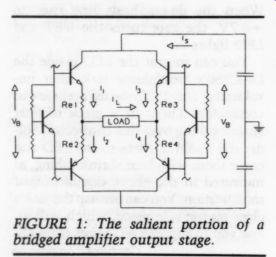
FIGURE 1: The salient portion of a bridged amplifier output stage.
The term “constant current” was originally applied to Class A tube amps. The tube circuit was not a current cancel ling bridge, but a Class A tube-biasing scheme. In his introduction of the concept, Howard T. Sterling (Journal of the Audio Engineering Society, Vol. 1, January 1953, pp. 16-21) recognized the ad vantages of constant current relating to power-supply internal impedance. The conventional tube amp choke-input supply resistance caused a significant change in voltage, thus in operating point, with the signal. This effect diminished when the plate load increased. The tube bias stability improved with a sacrifice in power and efficiency. In this discussion, I will restrict the meaning of “constant current ” to the reduction of supply cur rent changes with signal.
The benefits of extra supply filtering in transistor power amplifiers are well known. Adding extra supply capacitance is a common modification to improve sound quality. Beginning with a 200W Class A conventional amplifier, you'll find the value of each of the 40,000 uF supply capacitors increases to an effective 0.5F at average power levels in the constant current bridge configuration. In addition to reducing the effective power supply impedance, this configuration also eliminates crosstalk between circuits and reduces the chances of oscillation from sneak paths.
When you use a common supply for both sides of the Class A bridge, constant current operation is realized be cause current changes on both sides cancel, and only a direct current is required. Efficiency and power dissipation are the same for non-bridged Class A amplifiers. In practice, small signal operation gives exact cancellation. But in power circuitry, the cancellation diminishes at high load currents. I discovered this was due to the nonlinearities of the power transistors.
Figure 1 shows the salient portion of a bridged amplifier output stage. The bias voltage (Vz) and the base-to-emitter voltages of the power transistors (Vgg) are assumed constant with signal volt age in the ideal cause, thus:
ip +i) =1i3 + ig =1
Applying Norton's theorem to the transistor and load currents gives:
ig = ij + 13 ig
Therefore, for an ideal Class A bridged amplifier the supply current (ig) is a constant DC quantity equal to the idle current and is independent of load volt age and load current.
The amplified diode circuit normally used to generate Vj has a negligible volt age variation, but due to the base-to emitter volt-amp characteristic of the output transistors, the actual voltage across the emitter resistors is not constant, and slightly increases the bias current as the load current flows in either direction. The resulting supply current variations are twice the signal frequency with a magnitude that depends on circuit parameters.
The supply current waveform is approximately the load current squared.
The following analysis gives the amplitude of supply current variations.
The approximate expression for a BJT base-to-emitter volt-amp characteristic is:
Vee = Vr In{(ic)/ (Ico) + 1}
...where i. is the transistor collector current, I, is the reverse leakage current of the collector-base junction, and Vis the thermal energy voltage.
From the ideal case:
ig =1; +i3=1; + ip =
(Vre1)/ (Re) + (Vggs)/ (Re)
Applying Thevnin's theorem around the base loop yields:
Veer + Vre2 = VB - Vier - Vag2 and substituting:
ig = (Vg - Ve; - Vggz)/(Re)
The peak-to-peak supply current variation is given by:
Aig = (igati; = 0) - (ig at i; = peak) and the current in each transistor collector is:
ic; = (I +i) 72 ks = 0-5/2 Thus:
Aig = (Vt)/(Re) [21n{(1)/ (2c) +1} -
In{(ic;)/ (Ico) + 1} = In {(ic;)/ (Ico + 1}]
Idle current is much greater than leakage current, so we get:
Aig = (Vt)/(Re) [In{(I?)/(I? - i;2 + 4llo)}]
If the load current is less than the maximum for Class A operation by even a small amount, the leakage current term becomes negligible and the formula becomes:
Aig = (Vt)/(Re) [1n{(12)/(12 - i2)}]
The cancellation is not dependent on precise signal voltage balance at the load.
Similarly, reactive effects from the load will not affect cancellation if current peaks remain below the bias current. The frequency doubling of the residual sup ply current will further improve effective power supply series impedance.
Figure 2 shows peak-to-peak supply current as a function of load power for a Class A power amplifier.
For comparison, the peak-to-peak sup ply current for a conventional 200W non bridged Class A amplifier is plotted on the same graph. In this example, the bridged circuit current variation remains 20dB below the non-bridged variation up to about one-half power. The ratio closes to 13dB at three-quarters power. The analysis no longer applies when the cur rent is at or near full power, because one polarity of the output transistors begins to shut down. The power supply current...
CONSTANT CURRENT PERCENT FULL AC CURRENT 10 20 30 40 SO 60 70 80 90 PERCENT FULL POWER
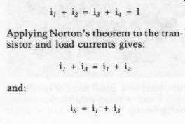
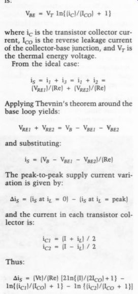
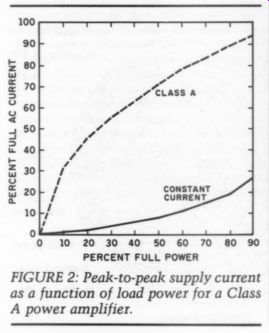
FIGURE 2: Peak-to-peak supply current as a function of load power for a Class A power amplifier.
...continues to increase, but the current waveform clips, as for any Class AB amplifier.
Further reductions for a given power level can be obtained by increasing the value of the emitter resistor. This option isn't desirable in a bridged circuit since output impedance must be kept low. The open loop output impedance is limited by the emitter resistors. Increasing the bias current also results in added cancellation and, of course, more power dissipation. Active devices other than bipolar transistors have similar nonlinearities that prevent complete cancellation.
One method you can try to improve performance at high power levels is to modify your amplified diode circuit (Fig. 3). The amplified diode modifications reduce the bias voltage (V;) and there fore the bias current, as the signal volt age magnitude increases. If you adjust the component values, a cancellation of an additional 15dB at high powers is possible. The much lower residual cur rent has four times the original signal frequency.
You can maintain the load-current performance in the bridged design by reducing the emitter resistor values and, if necessary, matching power transistors for equal current distribution. My amplifiers easily drive my 4-ohm ribbon speakers with 0.2 4-ohm emitter resistors and with a total of 16 output transistors per channel (eight for each side of the bridge). The additional cost of this bridged configuration is offset by the reduced voltage requirements on the transistors and capacitors, and by the required reduction in capacitance for a given supply impedance.
WILLIAM SNYDER Rochester, NY 14607
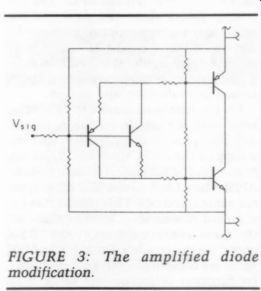
FIGURE 3: The amplified diode modification.
Letters
WORTHWHILE MOD
My Philips CD-670 modifications have improved its sound quality beyond my wildest imagination. I had been unsatisfied with the sound of most CD players and after reading about successful modifications in previous Audio Amateur articles, decided to attack the unit with side cutters and soldering iron.
To avoid running out of space halfway through the project, I built a second story on top of the existing unit using channel aluminum. The original metal cover can be made to fit on top of the new chassis which was carefully painted black and baked in an oven. The resulting player is now 1.5” higher and has a more nearly professional appearance.
Inside the new chassis I installed an additional power supply with its own power transformer and J. Didden wide band regulators ('A Wideband Power Supply,' TAA 1/87, p. 22). The +24V DC I obtained powers the new analog section.
With the help of previous TAA articles and the TDA 1541A D/A decoder chip, modification commenced. I removed the chip charging capacitors and replaced them with quality units mounted on a separate circuit board located in the up per chassis. This chassis consists of sides only (no bottom), therefore leads connected to the original circuit board are short and easily installed. I then fed the AO-R and AO-L audio outputs of the decoder chip to my new analog circuit consisting of an old Leach phono preamp (Audio, February 1977). This preamp has served me faithfully for more than a decade.
-----------------
Glad you asked that! Good Idea! You really have some great ideas, so why not share them with your fellow readers? We love to receive typed letters (or even better, a word processor file or output) including clearly written comments and questions. Not everyone's penmanship is easily discernable-please don't make us guess.
If you are responding to a previously published letter or article, please identify it by author; it helps us research and get the answers or comments you seek. In addition, include your full name and address on your letter in case we need to contact you (and your envelope goes south).
Direct your comments, questions, and concerns to Mailbox, The Audio Amateur, PO Box 576, Peterborough, NH 03458-0576. One more thing ... nclude a SASE if you expect a reply.
-----------------
The RIAA equalizing network was replaced with the proper de-emphasis circuit for the CD player. This stage re places the original op amp current-summing amplifier. The second op amp for the second and third pole of the low-pass filter was replaced with the Super Buffer ('The Buffer’ by Christopher Paul, TAA 1/88, p. 23). All these circuits were mounted in the upper chassis. I used high quality components and POOGE principles throughout. I have not yet in stalled a servo loop to eliminate the out put capacitor and plan to try one soon.
The output of the Super Buffer is connected directly to a power amplifier-a high quality, low power, DC-coupled, pure Class A design with a massive power supply. The speaker system is a sensitive three-way home-built affair; but that's another story.
In closing, I affirm that all this work has definitely been worthwhile. The resulting sound is very natural with notable improvements in piano and violin solos.
ADRIAAN HAMMER, 67600 Ebermunster, France
AMP SCHEMATIC NEEDED I RECENTLY OBTAINED
SAE Mark-31B power amplifier needing repair. The problem is SAE went out of business some time ago. I hope a fellow reader has, or can help me find, the 31B schematic.
In addition to the schematic, I also need to know the power transformer's secondary voltage/current rating and sources for the original power transistors or direct replacements.
Any help would be appreciated.
TRACY L. MORTON, Hauptstrasse 26 8702 Unterpleichfeld W. Germany
MARKETING GENIUS
I AM AN ENGINEER for a small company which manufactures Dial-Up Data Security Equipment. My sole function is to design circuit boards using CAD packages. I just received my first copy of Audio Amateur. Great publication.
To add to Luis Moeller's letter on CAD Shareware (TAA 1/92, p. 56), I have a suggestion. Our company uses P-CAD but recently PADS Software released a shareware version of their PADS PCB software. I thought if they made it shareware it must have a lot of limitations. Wrong. The only thing differentiating shareware from the expensive packages is the shareware version limits the number of components on the board.
The try-out version allows you to per form schematic capture, placement, and autorouting. These allow you to print, on dot matrix or laser, and to output Gerber plots. (Input files for board-making houses.)
-Ed.
I am pleased to tell the audio world about PADS. Anyone just starting in CAD board layout may contact PADS Software, Inc. at (800) 255-7814.
VINCENT CANULLI SR, Edison, NJ 08820
ANSI UPDATE
RICHARD MOORE ASKED for a source for the ANSI A-Weighting filter standard in his article ( “Building An A-Weighting Filter, ” TAA 2/92, p. 32). Stanley Lipshitz, who teaches applied mathematics and physics at the University of Waterloo in Ontario Canada, has kindly for warded a copy of the standard to author Moore. The document, from American National Standards, is “Design Response of Weighting Networks for Acoustical Measurements ” (ANSI S1.42-1986), (ASA 64-1986). The document is published by the American Institute of Physics for the Acoustical Society of America. The address for the document is: Standards Secretariat, Acoustical Society of America, 335 East 45th St., New York, NY 10017-3483.-E.T.D.
Dick Moore writes:
Stanley Lipshitz sent me the ANSI curve data for the A-weighting filter. The following tables show the data and the mods to the preamp circuit to meet the standard. Since the old NAB curve didn't appear in the article, this ANSI data can replace the curve entirely, being easier to use in evaluation and design.
Dr. Lipshitz (well-known to AES members) read my article on the A-weighting filter preamp and promptly sent me a copy of the ANSI specs for Weighting Networks For Acoustical Measurements.
ANSI, the ASA, and the IEC all employ the same standards. This means that the standard A-weighting curve values are the same as those shown as the 'B&K curve’ in the article's Table 1. The ANSI specs are computed from a precise transfer function definition and range from 1Hz to 100kHz. Here are the audio-band ANSI values for those who haven't seen the earlier data (the bullets indicate values found in Table 1):
Nominal Freq. Exact Freq. dB
The modifications to the circuit of the article's Fig. 3 to approach this curve are:
Component
Old New R6, 7 18k7 17k8 C7 33n 32n C10 9.4n 14n
For those who choose to use the simpler, alternative circuit of the article's Fig. 4:
The 28Kk ohm resistor at the amplifier in put changes to 27k4; the 12n output capacitor changes to 15n.
I haven't breadboarded either set of the new values; the changes to the circuit of Fig. 3 should result in very tight compliance (<0.1dB) from 20kHz down to 50Hz, with a maximum error of +0.6dB at 20Hz. The circuit of Fig. 4 may need more fiddling.
I again thank Dr. Lipshitz for such a quick response to my request for standards information. This kind of sharing s what makes TAA and the community of audio enthusiasts so special.
AUDIBLE DIFFERENCES
I ENJOYED Gary Galo's coverage in “A Report on the 91st AES Convention ” (TAA 1/92, p. 22). It makes me wish I'd been there. In reporting David Clark's remarks, Galo criticized him and his results based on the quote: 'All we come up with on amplifier tests are negatives-that we fail to hear a difference ” Mr. Clark is stating a scientific truth rather than admitting a failure. As he says, it is impossible to prove a negative, in this case, that differences cannot be heard. The A/B/X methodology can only “prove ” something that does happen, that differences can be heard. If they are not heard, it doesn't mean it is “proven” they don't exist, it only means they weren't heard. How ever, if they are heard, it proves they can be heard and, within the statistical probabilities stated, they do exist.
To again summarize the science, the only possible proof outcome occurs when differences are reliably heard. You are correct when you say that A/B/X testing “...has proven nothing... ” (italics yours). However, this is not, as you suggest, an indictment of worthless ness; it is simply the only scientific conclusion that can be drawn when audible differences have not been proven to exist. This does not mean they don't, it just means they haven't so far been shown to exist, under the conditions specified, by the listeners participating in the exercises. I believe amplifier differences are audible, although I have never heard differences among amplifiers operating in their linear range (i.e., not clipping, being overloaded at input or output, or showing pronounced frequency response errors), despite many occasions of testing and auditioning to perceive just such differences. I'm not one of those superbly equipped listeners, the “golden ears, ” just as I do not have 'perfect pitch,’ though I have known people who do.
DICK MOORE, Silverdale, WA 98383-9706
Contributing Editor, Gary Galo, replies:
Thanks for your comments on my AES report. In my opinion, Mr. Clark is trying to have it both ways, and that is the reason for my criticism. On the one hand, he and his followers dismiss those of us who claim to hear differences be tween amplifiers, preamps, etc. Since those differences haven't been proven by A/B/X testing, Mr. Clark and his followers believe those perceived differences are figments of our imaginations, and the results of unscientific listening comparisons.
On the other hand, at the AES convention he stated: “All we come up with on amplifier tests are negatives-that we fail to hear a difference. We cannot make the claim that there are no audible differences between amplifiers. ” Mr. Clark and his followers claim that if audible differences exist between two amplifiers, those differences will be revealed in a double-blind A/B/X test. But Mr. Clark has admitted that, after ten years of double-blind testing (with negative results), he can't claim audible differences don't exist. This is a contradiction, in my opinion.
All ten years of A/B/X testing has proven is that the A/B/X test consistently fails to reveal audible differences be tween amplifiers. Since Mr. Clark has admitted he can't deny the existence of audible differences between amplifiers, he and his followers are in no position to deride listeners who hear differences using methods of evaluation different from his own.
(Messrs. Clark, Galo, and Moore might take a look at “Some Amplifiers Do Sound Different ” by David Carlstrom, Arny Krueger, and Larry Green hill, (TAA 3/82, pp. 30-31.) The tests were double-blind A/B/X enabled.)
-Ed.
IN YOUR EAR I READ GARY GALO'S coverage of the fall '91 AES Convention (TAA, 1/92 p. 22) with interest as I also attended. I think, however, his report inadvertently mis characterizes the position of Dave Clark with regard to his opponents in the Great Debate. Gary correctly notes that Mr. Clark said null results of a double-blind test do not prove that amplifiers sound the same. Gary then mistakenly, I believe, concludes that ten years of double-blind testing have all been for nothing.
Dave was restating the oft forgotten statistical saw that null experimental results do not “prove ” the null hypothesis (there is no difference). An experimenter does not “accept ” the null, he merely does not reject it. In other words, you can never prove that amplifiers sound the same, you can only prove they are different.
On the other hand, careful analysis of the two dozen or so published double blind amplifier-listening tests finds the refrains of “I do not reject the null ” repeated with amazing regularity. While no one has ever proven there are no differences between well designed amplifiers, neither has anyone ever proven there are differences. Many, including the most zealous of subjectivists, have tried but all have failed.
Stanley Lipshitz and Dan Shanefield have repeatedly noted that the burden of proof in the Great Debate is played out on the wrong end of the field. In every other walk of life when one makes a claim, the burden of proof rests with the person making the claim. In the Great Debate, the innocent bystander risks being labeled an attacker just by asking for verification.
And so it is with Dave Clark. He and several other Detroit area audiophiles pioneered the A/B/X double-blind experimental methodology over a decade ago so they could prove the sonic worth of their audio projects to each other and to themselves. Now, because he has failed to prove the oppositions case about amplifiers, he has been labeled a closed-minded attacker. The opposite is much closer to the truth. Mr. Clark has been consistently attacked for presenting scientifically valid information that merely fails to prove the claims of his “opponents. ” Which brings me to the moral of this story. While the null hypothesis (amplifiers sound the same) will remain un proven forever, there comes a time when we should start behaving as though it were true. When the supposed differences between amplifiers repeatedly defy controlled verification, we should stop worrying about them and stop blasting away at the messenger. (See 'Some Amplifiers Do Sound Different,’ TAA, 3/82-Ed.). Paying more attention to loudspeakers, listening rooms, micro phones and better recordings offers far better expected sonic returns.
Don't get me wrong-I love sophisticated playback systems. But, because of people like Dave Clark, Stan Lipshitz, and Dan Shanefield, I no longer feel intimidated when others can produce equivalent sonic results with “lesser ” equipment. Instead, I applaud and emulate them. And, I no longer cower when confronted by snobbish audiophiles and salespeople who accuse me of insensitivity when I resist spending thousands of dollars on new amplifiers or cables when those same people lose their ability to identify the products when nothing more than the faceplates are removed.
I care about high-performance audio systems very much and am willing to go to practically any length to improve my system. Improvements should remain demonstrable when subjected to con trolled verification. Improvements that become elusive when bias controls are added to listening evaluations should be viewed with suspicion.
In summary, the results of A/B/X and other double-blind amplifier testing con ducted by closed-minded engineers has opened my eyes and plugged a serious leak in my wallet. I now concentrate my attention and direct my limited resources to loudspeakers with the highest payoff avenue to sound improvements. Why shoot the messenger? Tom NOUSAINE Cary, IL 60013 Fred Davis also writes:
As a new reader of TAA, I am not well acquainted with Gary Galo's writing and biases. On the other hand, his opinions of the '91 AES convention leave little doubt about the territory he treads, and our personal experiences at that convention differ considerably.
It interests me that he simultaneously dumps on the Tice Clock and supports 'high-end' cables. They are not as different as he suggests, since both rely on unsupported performance claims, and their purported operative mechanisms contradict well established principles of physics. Both groups can show anecdotal support (so can “Elvis ” followers, among others), yet neither can provide scientific proof. Concerning the clock, Mr. Tice himself admits (Stereophile 1/91, pp. 297-299 and 3/91, pp. 29-31) the circuit is not visibly altered since he claims to make changes at the “molecular level ” (no, Gary, a “Panasonic Interference Suppression Capacitor” is not added-it is still a $25 clock).
If a given claim arising from outside scientific research has sufficient popular support to invite a scientific inquiry, that is an excellent beginning. If, how ever, that scientific inquiry (properly de signed and conducted, of course) cannot show any real effect, then that effect is either imagined or too weak to detect reliably. The probability of no effect be comes much stronger as the number of test subjects increases. If the sample population tested is not particularly sensitive to the claimed effect, the results will be biased more negatively and vice versa.
If the population of “golden ears' is really interested in proving an effect to be true (and rubbing engineering noses in it), it would behoove that sensitive hearing group to encourage as many members as possible to take part in such a study, since this could bias the results to be more positive, potentially to the point of proving the claim in a way that would be difficult to dispute. This could provide enough fodder to keep high-end editorials running for half a century. On the other hand, the opposite is also possible. Should the results turn out negative, then that is exactly what the data indicates. (Not that negative results have inhibited certain editors, manufacturers, or consumers. Hope springs eternal.) The study of human perception and responses has been continuing for hundreds (thousands?) of years. In order to separate real response from placebo effect and illusion, researchers developed double-blind tests which have been used successfully for decades. If negative results are obtained from ten years of study, the probability of finding a positive result is remote but not impossible.
If the investigator believes the results are not conclusive, then perhaps he is either being extremely cautious or does not believe a large enough sample has been taken. Either way, the data in Mr.
Clark's case leaves little doubt that the results are strongly distributed to the negative (which in no way invalidates the data nor makes the tests useless).
Certainly no one argues the difficulties of performing a listening test in a large auditorium. On the other hand, some reviewers and manufacturers make claims that should easily be heard even in the worst of circumstances. The two cables used in the A/B/X trial were Belden 8477, a common 12-gauge cable used widely in commercial applications, and the Music Interface Technologies CVT, an expensive (but not the most ex pensive) high-end cable. The plot of series impedance for these two cables, takes into account the combined effects of resistance, inductance, and capacitance versus frequency, shows very little difference even with a greatly expand ed vertical scale. The difference is only about 0.00 8-ohm (compared to 8 ohm, a difference of 0.1% or -60dB).
Can you tell which cable is superior? How is it possible for these two cables to sound different with the same amplifier and speaker? Certainly you are not suggesting a new, undiscovered form of electrical unit? The trilogy of R, C, and L have been sufficient to model the behavior of circuits and wire from DC to daylight for decades, and that seems un likely to change in the future. By the way, the Belden 8477 is curve A, which has a consistently lower impedance (al though quite small) across the audio spectrum.
Personally, I think that trusting only in measured data seems a bit silly, since amplifier tests are not made with my particular brand of speakers in my listening room. On the other hand, buying an amplifier without any knowledge of its test performance is also a bit silly, since those tests can provide valuable in formation, especially concerning its ability to drive difficult loads (which your speakers may very well exhibit, again revealed through measurement). Please understand that I am not talking about equating measured data to audible perception. Measuring the capabilities of an amplifier, for example, can quantify its power, bandwidth, frequency response, and nonlinearities, but they will tell you little of the quality of the performance or recording it reproduces, only how it will alter that signal into a resistive load (usually).
Furthermore, practically all measurements to an amplifier never take into consideration its performance with a speaker system (much less your particular brand) as a load, nor the acoustical result. The reasons for not doing so are obvious since the number of variables involved are staggering, and the distortion of the speaker and acoustical effects of the listening room will be far greater (in almost every case) than the effects of the amplifier, and mask any subtleties in the amplifier and amplifier/speaker interactions in listening tests. A room can alter the frequency response of a speaker by 20dB or more, yet an amplifier with a 20dB response variation would be laughed into the garbage can.
A speaker can add 10% (or more) distortion which masks the fractional percentage distortion contributed by the amplifier (operating normally, of course).
So when I read a speaker cable review with such claims as “the experience was a shocker-totally pristine harmonic textures, vanishing levels of grain and grundge, more inner detail and inter transient silence than ever before, and incredible clarity, “ I have to be skeptical. Unless the cable is causing or al lowing the amplifier to produce spurious signals that are audibly reproduced by the speaker, the incredibly minute effects directly attributable to the cable (as discussed in my report in the JAES) will certainly be masked by other more significant effects, especially acoustical ones.
If Monster Cable truly has measurements that show how their cables are (audibly?) better, I would be most eager to see that data and review their methods. I have seen their literature, which leaves me to wonder why the FTC has not taken them to task about claims that blatantly violate laws of physics and common sense. Galo's statement ( ”...Monster Cable has measurements which show how their cables perform differently from those of other manufacturers. .. ”') does leave the impression that they claim to be different but not better (he does not mention audibility).
I was most surprised Galo accepted Clark Johnsen's “triple blind ” test with out question, especially when subjectivists are so opposed to any blind tests (not the least of whom is Bob Harley whose presentation he appeared to like so much). Results can only be convincing if tests are valid. Mr. Galo is the first person I have heard (other than Clark) who has not expressed serious doubts about his method. When I outlined several major difficulties with his test, he replied 'I find them [the difficulties] trivial. ” This brings images of the feisty knight in Monty Python's Holy Grail, who loses limb after limb only to reply, “It's only a flesh wound. ” There have been valid tests that indicate the audibility of absolute polarity, but a faulty test does not produce valid data, and his 'triple blind’ results prove nothing.
I do not believe we need more debate.
We have certainly seen enough of that with no substantial outcome. What is needed is more real data, unquestionable scientifically valid data, that will put to rest the debate once and for all. Are subjectivists willing to put their ears on the line and take the risk? I hope so.
(Messrs. Clark, Davis, Galo, Moore and Nousaine might take a look at 'Some Amplifiers Do Sound Different’ by David Carlstrom, Arny Krueger, and Larry Greenhill, (TAA 3/82, pp. 30-31.) The tests were double-blind A/B/X enabled.)
-Ed.
Gary Galo replies:
I've decided to write one reply to the letters from Mr. Davis and Mr. Nousaine since they cover much of the same territory. Mr. Davis seems to believe that the subjective vs. scientific controversy is strictly a black and white issue. People involved in audio are either scientists or charlatans-there's absolutely no middle ground. I disagree strongly with this oversimplified view, as anyone who read my report should be able to see. The issue at hand isn't nearly that simple. In fact, I don't know of any issue worth investigating that is. There is a very large gray area between the two extremes which Mr. Davis is not recognizing.
From my own perspective, the individuals who contribute the most to audio (or any field, for that matter) are those who admit to the gray areas.
There's no question that high-end audio has its share of mystics, but they hardly represent the entire industry. Many conscientious listeners don't buy into the “every-change-is-an-improvement ” school of thought. The manufacturers, reviewers, and audiophiles I respect are those who can separate the BS and other wise outrageous claims from those things which do make a difference. As we saw at AES, many subjective listeners also have solid technical credentials, a fact which the “scientists ” have difficulty accepting, or choose to ignore.
I have no way of knowing whether or not the circuitry in the Tice Clock is altered since I've never opened one up and compared it to the Radio Shack clock. Mr. Davis seems to be accepting the manufacturer's explanation that the circuitry hasn't been altered. I've been skeptical since I haven't actually seen one (funny how the tables seem to be turned here), but I'm willing to look if one is sent to me.
I believe cables sound different from one another because I clearly hear those differences in my own system. This doesn't mean that I endorse spending $2,600 on a pair of speaker cables-my power amps didn't cost that much! The cables I use cost $2 per foot.
Interconnect cables are actually quite easy to evaluate because level matching isn't an issue. Listen to a recording with one interconnect, change the cables, and listen again. None of the MAAD parameters are changed, unless the cables have unusual capacitive or inductive characteristics. If you're evaluating speaker cables, you must ensure that the resistances of the various cables don't change the level, but I would never consider using speaker cables with resistance so high that they actually reduced the volume level by more than 0.1dB. Among other factors, I do believe in using speaker cables with very low series resistance.
Both Mr. Nousaine and Mr. Davis seem to be apologizing for David Clark's statement, “We cannot make the conclusion that there are no differences be tween amplifiers.' David Clark made the statement, not me. I didn't mischaracterize him-I quoted him verbatim from the taped transcript. I don't believe my conclusions are mistaken. If, by his own admission, he can't claim that differences don't exist, then he should stop attacking those of us who do hear differences. He has said, in effect, “we can't prove that there are differences, but neither can we prove that there aren't. ”' Yes, I'm aware of the fact that you can't prove a negative, but that's precisely the point. Ten years of A/B/X testing has proven that the testing procedure consistently fails to reveal audible differences between amplifiers, and that is all. Based on Mr. Clark's statement, I don't believe he is in any position to continue his attacks on those who claim to hear differences. My views on this subject are not an attack on him, but simply my assessment of the situation. I certainly don't view the letters from Mr. Davis and Mr. Nousaine as an attack on me. They are entitled to their own assessments.
Double-blind testing has had an enormously positive effect in many areas of science, including medical research. But, it's a mistake to conclude that success in other areas makes double-blind testing suitable for the evaluation of systems which reproduce music. There's been plenty of justifiable criticism of double-blind A/B/X testing over the past ten years, but you gentlemen seem to ignore the criticisms. I can't help but notice that neither of you mentioned Michael Gerzon’s paper “Limitations of Double-Blind A/B Listening Tests. ” The history of audio is full of in stances where test results have contradicted reality. Early solid state amplifiers measured better, in some respects, than their tubed counterparts, yet most of us thought they sounded worse. Then, along came new measurements for slewing-induced distortion and transient intermodulation distortion, and suddenly the critical listeners were vindicated.
The new measurements showed that there were problems not revealed by previous testing.
And so it is with double-blind A/B/X testing. I know that preamps and amplifiers sound different from each other because I consistently hear those differences, even with levels matched. Over the past several months I've done many listening comparisons between my highly modified Magnavox CDB650 as a stand-alone unit, and the 650 used as a transport played through my POOGE 5 DAC960 (TAA 2/92 p. 10, and 3/92 p. 34). The output levels of the two D/A converters are within 0.1dB, according to my Loftech meter.
The POOGE 5 DAC960 consistently reproduces a larger soundstage, more precise stereo imaging, greater inner detail, more hall ambience and better dynamic contrasts-differences readily apparent during short-term comparisons, as well as long-term listening. On several occasions, I've had the DAC960 on the bench for further refinements, so the stand alone 650 had to be reconnected to my system. People who hear my system regularly aren't fooled-they are no longer satisfied with the performance of the modified CDB650.
The POOGE 5 DAC960 project involved many painstaking hours of modifying, measuring and listening, again and again. We had setbacks which resulted in unsatisfactory sonic performance. We didn't shoot the messenger (our messenger, that is)-we tracked down and fixed the problems. I'm extremely proud of the results, and I stand by the methods we used to achieve them. I'm certain that we'd still be evaluating changes ten years from now if we relied on double-blind A/B/X testing to determine the validity of every modification.
I doubt that Mr. Davis and Mr. Nousaine believe in long-term aural memory. I disagree. Trained listeners have the ability to remember the sonic characteristics of their systems, just as some musicians have perfect pitch.
I've heard live orchestral music in Avery Fisher Hall on a number of occasions. If I described the acoustical weak nesses of that hall, no experienced listener who's been there would disagree.
Neither would most acousticians. Sit ting about two-thirds of the way back in the orchestra section, the sound is dry and harsh. No matter how loud the orchestra is playing, the sound never seems to escape beyond the proscenium.
The sound doesn't come out and envelope you the way it does at the Metropolitan Opera (or pre-renovation Carnegie). Every time I hear music in Avery Fisher Hall, the same problems are revealed.
Am I, and everyone else who has been to the hall, crazy! Are we really unable to remember the sonic characteristics! If these gentlemen accept this premise, there's no reason to doubt that aural memory will work just as well when listening to reproduced music. I'm sure Mr. Davis and Mr. Nousaine don't believe that all audible differences between the sound of concert halls are due to frequency response, level and absolute polarity (or even reverberation time).
It has been nearly two years since I began to realize the importance of power line filtering. About a year before I began using power-line filtering, I purchased several of the first Mercury CD reissues.
Among these was Antal Dorati's performance of Respighi's The Birds, a particularly difficult recording to reproduce properly. Prior to adding power-line filtering, this disc never did sound right.
The strings were always grungy and rough, sometimes bordering on what I would consider distortion. At its worst, the sound was similar (though not as bad) as the string sound we heard at the AES cable demonstration (I hope that Mr.
Davis and Mr. Nousaine didn't consider that system even remotely acceptable).
Since adding filtering to my system, this disc has consistently sounded clean and well defined. Why is it that for the past eighteen months, this recording has sounded consistently good, and yet for a year prior to that it sounded consistently bad! Surely my listening took place over a large enough time period to average out personal biases, changes in mood, tendencies toward self-delusion, and so on.
I can't accept the conclusions of a “test” which produces results different from those I've just described. I'm the one who must listen to my audio system on a daily basis. If I find one or more aspects of its performance consistently unsatisfactory, I will take steps to correct its performance, as I have done on many occasions. If a double-blind A/B/X test fails to reveal an improvement which I find, after repeated long-term listening, has solved the problem, then the sensitivity of the A/B/X test must be called into question.
I disagree with Mr. Davis' assertion that some differences should be audible under even the worst of circumstances.
I'm not defending the often exaggerated claims of some high-end manufacturers.
There are charlatans in every business, including high-end audio. As I pointed out earlier, the competent reviewers and listeners can sort out the BS from the claims which have merit.
Differences which seem “dramatic ” on one system may be subtle to nonexistent on another. It simply depends on how revealing the rest of the system is.
My audio system at home is, I believe, quite refined. It is extremely revealing of even minor changes (notice I didn't say improvements-not all changes are positive, and I must often sort these out). The performance of my system isn't due to any single factor. I have
spent years carefully optimizing every link in the reproduction chain to achieve this level of performance, and the optimization is an ongoing process.
My audio production studio at work has the same loudspeaker system as I use at home, and a more than decent power amp, preamp, CD player, and so forth. But, this system isn't nearly as refined as what I have at home. I am often unable to hear changes with my studio system that are immediately obvious at home. Remember, the loud speakers are the same, and many of the limitations in my studio system have nothing to do with room acoustics. Am I consistently sane and rational at work, only to become consistently irrational and self-deluding at home! I often find it frustrating that many of the characteristics of my own recordings, both positive and negative, aren't revealed by my studio system. I have to haul a DAT machine home (now played through the POOGE 5 DAC960) to really hear what my microphones and recording techniques have produced.
Mr. Nousaine is correct: microphones and recording techniques make a big difference. Producing a good recording is half the battle, but only half. You also need a refined playback system to really hear what's on your master tapes.
I'm certainly not implying the existence of any undiscovered electrical units. But, taking R, C, and L at face value isn't going to tell the whole story.
Let's take capacitance. Early in 1980, Walt Jung and Richard Marsh published a two-part series in Audio ( “Picking Capacitors,” (Audio, Feb. and March 1980, Parts I, II). They showed how various dielectric materials have different measured behavior, even though the capacitance may be the same. Jung and Marsh gave us measurements to illustrate how various dielectric materials perform under AC conditions, and which ones perform best.
I, for one, am not looking to ‘rub the engineers' noses in it.' I accept the fact that David Clark, Peter Aczel, Mr. Davis, and Mr. Nousaine can't hear differences between amplifiers, preamps, cables, etc. I don't have the time or the interest to try to convince them other wise. I realized long ago that trying to convince objectivists that audible differences exist is futile.
What I do have the time and love for, as a music lover and audio journalist, is sharing my reviews, modifications, and other audio ideas with those who can hear the differences. I'm also not interested in placing a ‘burden of proof’ on anyone. Some listeners can hear the differences and others can't. I accept that.
Some engineers, reviewers and listeners can separate the boloney from the valid.
Some can't. I accept that, also.
If Mr. Davis is, indeed, “most eager to see ” Monster Cable's measurements, why didn't he, or some other “scientific ” member of the panel, insist that at least one cable manufacturer be rep resented! Perhaps the organizers of the workshop just assumed that the folks at Monster Cable, like everyone else in high-end audio, are charlatans totally in capable of defending themselves with any meaningful data. Or, perhaps the possibility of a meaningful public defense ran contrary to the agenda of the organizers. I suspect the latter. At any rate, his sudden interest in Monster Cable's measurements is a bit late, I believe.
I hope Mr. Davis is equally eager to see the Jung and Marsh measurements on capacitors. The articles have been around for twelve years now, so they should be easy to find. Meanwhile, we can only hope that Monster Cable, and other manufacturers, are invited to pre sent their data at the next convention.
What we clearly need is an entirely new battery of measurements which accurately simulate the dynamic conditions of real music. I expressed my opinions on the limitations of present test methods on the second page of my re port. Unfortunately, we are probably years away from testing procedures which accurately simulate the demands placed on an amplifier by a 100-member symphony orchestra playing Mahler's Fifth Symphony. In fact, we don't appear to be remotely close to simulating the demands of a string quartet performing Beethoven's Op. 18, No. 1.
Measurements are extremely important in the design and evaluation of audio equipment, but they don't tell us everything we need to know. Until we have measurements which accurately simulate the demands of real music, our ears must be the final arbitrators. Recording engineers don't rely on measurements or double-blind A/B/X tests to determine microphone locations. I doubt that most recording engineers believe that these tests are needed, or even desirable for this purpose. Many recording engineers find that moving a pair of microphones just a few inches can change the sound. Would Mr. Davis and Mr. Nousaine insist that the claimed audibility be demonstrated with double blind testing, or measurements! Of course, I'm fully aware that there are mathematical rules which can help recordists avoid phase cancellations and comb filtering effects in a multi- micro phone situation. Beyond that, measurements don't tell us how finished product will sound.
As someone who is actively involved in building, modifying, and evaluating audio equipment, as well as recording a considerable number of live concerts each year, I can assure Mr. Davis that changes in circuit topology often pro duce changes in stereo image, sound stage depth, inner detail and hall ambience every bit as dramatic as moving a pair of microphones to a new location (or moving your ears to a new location in the hall).
I'm not implying that preamp or amplifier circuit topologies should some how “manufacture ” soundstage depth, ambience and imaging. The circuitry's task is to accurately reproduce the electricals, signal generated by the microphones, thus recreating the soundstage characteristics of the master tape, or at least allowing the loudspeakers to do so.
But, as Robert Harley pointed out in his paper, we don't have any measurements to quantify these characteristics. Recording engineers aren't afraid to trust their ears, and experienced listeners who hear their recordings shouldn't be either.
I certainly sympathize with Mr. Nousaine's distaste for snobbery in high-end audio. I wrote a guest editorial on that subject years ago (TAA 3/86 p. 6). I think he'd like at least parts of it. I'm not ashamed that I use a pair of ADCOM 585 power amps-one of them modified-rather than Krells. I certainly can't afford Krells. But, part of the challenge of audio for me is modifying affordable equipment to achieve a level of performance approaching far more expensive equipment. I've never modified any clocks, nor do I have any intention of doing so.
I also agree with Mr. Nousaine's insistence that costly improvements be demonstrated. We simply disagree on the methods of demonstration. I reject listening tests which fail to reveal differences that I've demonstrated time and time again using my own procedures. I won't use a circuit design which makes my system consistently unsatisfactory many more than I would use a microphone placement that makes consistently unsatisfactory recordings.
I don't know how Mr. Davis could conclude that I accept Clark Johnsen's “triple blind ”' test “without question. ” I did not endorse this test in any way-I simply said that his justification for using it to assess the audibility of absolute polarity was convincing. I found Johnsen's presentation “enormously refreshing ” because of his unashamed enthusiasm for his topic, a striking contrast to the overly stuffy presentations by many of the AES authors. But please don't be left with the impression that I find all scientists to be stuffy-far from it. Anyone who attended Dr. Stanley Lipshitz's paper on “Quantization and Dither ” knows that it's perfectly accept able for a respected scientist to show genuine excitement about his subject matter. I thoroughly enjoyed Dr. Lipshitz's presentation. Needless to say, his authority on this subject is unquestioned.
Mr. Davis' last paragraph is particularly disturbing. He seems to be saying “we know we re right, all we need is the scientific data to prove it. ” I don't know how he can say he is “most eager' to evaluate Monster Cable's data and methods, and yet only two paragraphs later express a desire to end all debate on the controversy. Next time Mr. Davis is invited to participate in a panel discussion on this subject, I hope he will insist that his opponents are given fair representation.
-------
Also see:
BUILD THE A75 POWER AMPLIFIER PART 1