By Richard S. Burwen [ Burwen Laboratories, 12 Holmes Road, Lexington, Massachusetts 02173]
NOISE IS A PROBLEM! You can't escape it. It is in the environment, electronics used for recording, records, tapes, AM, FM, TV, microwave, and other audio communication media. Noise in studio tape recorders is too high for much of the musical program material being recorded today. Studios without noise reduction equipment usually overcome noise by such undesirable methods as (1) recording at such a high level that peaks far exceed the 1% or even the 10% distortion level of the tape, (2) limiting the signal before recording or (3) monitoring through a speaker system that attenuates the very high frequencies. The rather serious limitations of these methods have been overcome by electronic noise reduction.
Among the three principal methods of noise reduction available for studio mastering two of them, the Dolby Laboratories Noise Reduction System (Patent pending) and the Burwen Laboratories Noise Eliminator, involve compression of the signal before recording. As a result the signal recorded on the tape is nonstandard and a separate noise reduction channel must be used for each track in multitrack recording.
A third system, the Dynamic Noise Filter, Fig. 1, manufactured by Burwen Laboratories, is much simpler, requires far less equipment, eliminates the problems of nonstandard tapes, and is more versatile than either of the two systems mentioned above. For example, a single two-channel Dynamic Noise Filter operating on a two-track master tape output feeding a disc cutting system, as illustrated in Fig. 2, reduces the cumulative noise from all sources ahead of it. Thus two channels of the Dynamic Noise Filter do the job of 18 channels of the other types in the 16-track system of Fig. 2. One of the key advantages of the Dynamic Noise Filter is that it may be used to reduce the noise in any program material without the need for special processing and without audibly affecting the signals.
Principles of Operation
The operation of the Dynamic Noise Filter is based on two principles: (a) the noise output of an electronic system is dependent upon the system bandwidth and (b) the human auditory system "masks out" noise in the presence of the desired signal at frequencies in the vicinity of the signal frequency when the signal-to-noise ratio is sufficiently high. The Dynamic Noise Filter can be described as an automatically variable bandpass filter whose bandwidth changes rapidly with each musical note and whose high and low frequency cutoffs are independently controlled by the spectral content of the input signal. Figure 3 illustrates the Filter's dynamic frequency response. Noise reduction is achieved by restricting the bandwidth at high and low frequencies when the signal level is very low (the minimum bandwidth is 800 Hz). At medium and high signal levels it passes the full 20 Hz to 20 kHz bandwidth.
As in the other noise reduction systems, the Filter reduces noise only for low level signals; the noise is passed along with the high level signals. However, due to the characteristics of the ear, the noise that is present during each note is masked by the music.
The noise reduction, as shown by the minimum bandwidth curve in Fig. 3, is 25 dB @ 30 Hz and 22 dB @ 10 kHz. On 7 1/2 or 15 ips unweighted tape noise the reduction measured typically 10 to 11 dB. Because noise reduction is attainable without any special preprocessing of the signal, the Dynamic Noise Filter is useful not only for a multitrack mix or a master tape playback but also for prerecorded tape, cartridges, cassettes, records, FM programs, or video tape sound.
This versatility comes, of course, at a sacrifice-the bandwidth is restricted for low level signals. However, as will be shown later full bandwidth is attained at such low signal levels and in such a short time that the effect of the Dynamic Noise Filter on most good quality program material is completely inaudible except for the reduction of noise. When musical instruments are played at such a low level that the bandwidth is restricted, they usually produce much less overtone output and little is lost by the attenuation of the high frequencies.
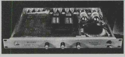
Fig. 1-The Dynamic Noise Filter chassis accommodates modules for 1,
2, 3, or 4 channels.

Fig. 2-Two-channel Dynamic Noise Filter reduces noise in a 16 track
system.
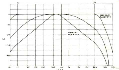
Fig. 3-The frequency response varies with the _if'" level. r "
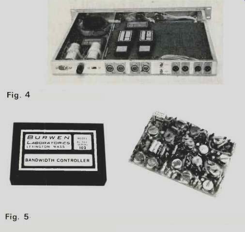
Fig. 4--Rear view. Fig. 5--A high performance module incorporating 15 operational
amplifiers.
Design Simplification
The system described here is a simplification of an extremely flexible and highly complex Dynamic Noise Filter' system described in an earlier paper. The previous system, built in three channels, incorporated precision multipliers and integrators for bandwidth control and used a total of 320 integrated circuit operational amplifiers mounted on 57 plug-in circuit cards. It provided a choice of cutoff frequencies of 6, 12 or 18 dB/octave at high and low frequencies, a variety of bandwidth limiting functions, four-frequency notch filtering for hum and rumble, and a unique click limiter to eliminate noise impulses from phonograph records. Experiments made with this unit on a wide variety of program material indicated that the steeper slopes were preferred mainly for old material having high frequency distortion or completely lacking in the very high frequencies. For wide frequency range program material it was found that the same noise reduction could be achieved using a 6 dB/octave filter having a high cutoff frequency considerably below the minimum tolerable for 12 or 18 dB/octave filters. Furthermore, the 6 dB/octave filter seems to produce smoother operation on low level classical music.
In an instrument optimized for studio mastering, the notch filters for hum and rumble along with the click limiter and a number of the controls were deemed expendable luxuries.
The use of common control circuits for two channels saved a considerable number of components while preserving the stereo balance. Thus a simplified Dynamic Noise Filter, Figs. 1 and 4, evolved having a minimum of controls and accommodating 1, 2, 3, or 4 channels on a single l'%" high rack panel. Operational amplifiers are still used extensively to achieve a 100 dB dynamic range with 0.01% midband harmonic distortion. The system is built using high quality, reliable plug-in modules, such as is shown in Fig. 5, involving a total of 80 operational amplifiers for four channels with as many as 15 in a single module.
Block Diagram
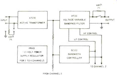
Fig. 6--Single channel system diagram.
The modules can be arranged into as many as four signal channels and the configuration for one channel is illustrated in Fig. 6. The input signal is first fed to the active transformer which is a unique differential input d.c. amplifier. It serves the same function as a conventional audio transformer and provides the same common mode rejection while overcoming the transformer's limitations in frequency response, distortion, and hum pickup. The signal from the active transformer is fed to two other modules, the voltage variable bandpass filter and the bandwidth controller, which form the heart of the noise reduction system. At the input to the bandwidth controller signals from two channels are added. Inside the module the high and low frequency components are selected out and individually rectified, filtered, and compressed to form two separate d.c. control voltages that adjust the cutoff frequencies of the voltage variable bandpass filter. The control voltages vary the bandwidth of the system in relationship to both the frequency content and level of the input program material.
The Voltage Variable Bandpass Filter
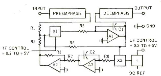
Fig. 7--Block diagram of Voltage Variable Bandpass Filter module.
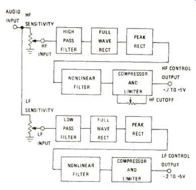
Fig. 8--Block diagram of the Bandwidth Controller.
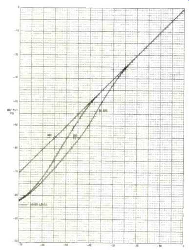
Fig. 9--Output vs input at 85 Hz, 650 Hz, and 6.6 kHz.
The key module in the noise reduction system, the voltage variable bandpass filter, is shown in block form in Fig. 7.
The signal from the active transformer is brought to the input of the module where a feedback type pre-emphasis network increases the high frequency gain at 6 dB/octave above 3 kHz for the purpose of increasing the signal-to-noise ratio. At the output of the module the response is flattened by a complementary de-emphasis network and output buffer amplifier.
Following the pre-emphasis network the signal passes through a multiplier, X 1, which attenuates the signal in accordance with the value of the high frequency d.c. control voltage produced by the bandwidth controller. The multiplier then feeds the main signal operational amplifier, Al, which in turn delivers its output to the de-emphasis network. Three separate feedback paths around Al determine the high, middle, and low frequency gains of the module.
The first feedback path via capacitor C1 converts A1 into an integrator and reduces the high frequency gain. The gain from the input to the output at very high frequencies is the product of the gain of the multiplier X1 and the integrator Al. At middle and low frequencies, where the gain allowed by capacitor C1 is high, the closed loop gain is determined by the ratio of the values of resistors R6/R1. At low frequencies the feedback is further increased by the multiplier X2, the integrator A3, and the inverter A2. Combining the three feedback paths produces virtually infinite d.c. feedback and reduces the system gain to 0 at d.c.
Changing the high frequency cutoff point is achieved by varying the high frequency control voltage supplied by the bandwidth controller. Increasing the control voltage on multi plier X1 effectively reduces the time constant of integrator Al and raises the high frequency cutoff in direct proportion to the voltage.
The low frequency cutoff is changed by causing the feedback path made up of integrator A3 and multiplier X2 to predominate over R6 at low frequencies. Changes in the gain of the multiplier and the effective time constant of the integrator are caused by the low frequency control voltage generated by the bandwidth controller. Increasing the d.c. control voltage delivered to the multiplier X2 effectively reduces the time constant of the integrator A3 and raises the low cutoff frequency. What is desired is a reduction in low cutoff frequency for an increase in low frequency control voltage. To accomplish this, the value of the low frequency control voltage is inverted by dividing it into a d.c. reference in the divider block causing a value to +0.2 V to produce a 350 Hz frequency cutoff and +5 V to produce a 13 Hz low frequency cutoff.
The frequency response curves produced for d.c. control voltages of 0.2 V, 1V, and 5V at both control inputs are the same as in Fig. 3. Note that the midband gain is constant and determined by R6/R1 and the wideband response is flat within 0.2 dB from 20 Hz to 20 kHz. These curves are very similar to the curves that would be produced by feedback around Al via R6 at middle frequencies, through a variable capacitor at high frequencies, and through a variable inductor at low frequencies if the remaining components were removed.
The Bandwidth Controller
Bandwidth controller which produces the high and low c, control voltages is shown in more detail in Fig. 8. External to the module are high frequency sensitivity and low frequency sensitivity potentiometers which divide down the summed output of the active transformers in channels 1 and 2. The arm of the high frequency sensitivity potentiometer feeds a high pass filter which selects out frequencies primarily in the vicinity of 6.6 kHz and provides considerable amplification. The high frequencies are then full wave rectified and peak rectified using a precision feedback circuit that produces accuracy down to millivolt levels. A multiple section nonlinear filter is used to smooth the output of the peak rectifier sufficiently to eliminate modulation of the bandwidth at any audio frequency. The filter is a nonlinear feedback system which can charge rapidly and takes only 1 mS to reach full output. Its decay time is approximately 50 mS to within 10% of final value. The output of the nonlinear filter passes through a compressor and limiter circuit which increases the effect a small audio input has on the bandwidth. An external high frequency cutoff potentiometer places an upper limit on the +0.2 to +5 V control voltage anywhere within this range, and may be used to limit the bandwidth for poor quality or distorted program material.
The low frequency d.c. control voltage is generated in the same manner as the high frequency control voltage following the low frequency sensitivity potentiometer. In this part of the bandwidth controller the low frequencies primarily in the vicinity of 85 Hz are used to produce the d.c. control output and the time constants are longer. The low frequency attack time to produce +5 V output from an overdrive input is 10 mS and the decay time is approximately 500 mS to within 10% of the final value. The low frequency part of the controller is about 14 dB less sensitive than the high frequency section because music tends to have more low frequency energy than high frequency energy.
In choosing the attack and decay time constants for the high and low frequency sections of the bandwidth controller, an attack time of 1 mS to attain the full 32 kHz bandwidth was found to be short enough for no audible effect on musical transients. On the other hand, it was found undesirable to shorten the attack time further because this allowed the ticks on a record to actuate the filter. The decay time seemed to be optimum at about 50 mS to within 10% of final value. A shorter time reduced the effective reverberation in the program material and a longer time allowed more noise to be heard between the notes.
The low frequency attack and decay times appeared to be somewhat less critical but had to be longer to support the low frequency response and prevent more than 0.05% harmonic distortion on a low level 20 Hz signal.
Other Features
Each channel has a differential input with a 100k impedance which may be changed to 600 ohms by means of a rear panel switch. The overall voltage gain of each channel is 0 dB ±0.1 dB and the maximum output is ± 11V instantaneous peak into an open circuit, + 18 dBm into 600 ohms, or + 16 dBm into 150 ohms. The output is single ended, grounded to the chassis and has an internal impedance of 0.4 ohms to which 600 ohms can be added by means of a rear panel switch.
A 0.01% regulated ± 15 V power supply powers all four channels. The transformer is toroidal for low external magnetic field, and the positive and negative voltages are interlocked and overvoltage protected so that a supply failure will not damage the other modules.
Performance
A measurement of the output vs input, Fig. 9, shows that the Dynamic Noise Filter behaves as a linear amplifier at 650 Hz but appears to be a low level expander at 85 Hz and 6.6 kHz. These measurements were made at the typical control setting used when playing a multitrack mix or a master tape.
It can be seen that the expansion takes place at a very low level in the range of -75 to -35 VU at 6.6 kHz. What is really happening, of course, is that the bandwidth is being extended as the signal increases.
Another way of looking at this same effect is to plot the-3 dB bandwidth vs input as shown in Fig. 10 at 85 Hz and in Fig. 11 at 6.6 kHz. These frequencies are the points at which […] . bandwidth controller is most sensitive as shown by the […] of the bandwidth controller filters in Fig. 12.
At other test frequencies the bandwidth variation will occur at higher levels as determined by these curves.
The sensitivity can be varied over a wide range to shift the curves in Figs. 9, 10, and 11 up and down in level to suit the particular program material. Generally, the low frequency sensitivity is set so that rumble just begins to operate the low frequency filter and the high frequency sensitivity is set so that hiss just begins to operate the high frequency filter.
As in other types of noise reduction systems, the Dynamic Noise Filter discriminates best between the music and the noise when the signal-to-noise ratio is high initially. When used with extremely noisy program material such as a 78 rpm record, the controls have to be set for a compromise between noise reduction and degradation of the program material.
Many 78 rpm records contain only noise and distortion in the region of 6.6 kHz and there is some advantage in cutting off the high frequencies at 12 dB/octave at a somewhat lower frequency ahead of the Dynamic Noise Filter. Since the filter attenuates the high frequencies at small signals as low as 1100 Hz, it produces worthwhile noise reduction in excess of that attainable with a fixed filter. The tone can be balanced for pleasing response following the Dynamic Noise Filter.
In listening tests an interesting psychological effect was observed. A reduction in tape hiss seems to be accompanied by an attenuation of the high frequency content in the program material even when it does not actually occur. This effect can be confirmed by adding hiss to a noise-free signal in which case the high frequency output seems to be somewhat increased.
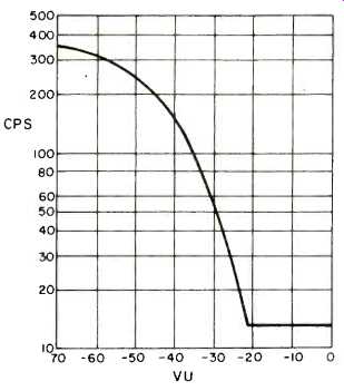
Fig. 10--Low frequency cutoff vs input at 85 Hz.
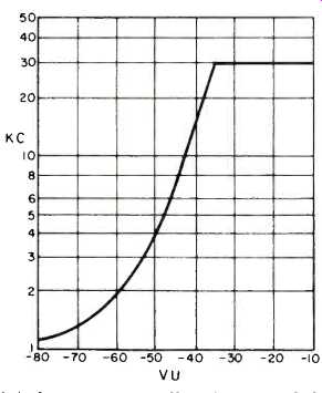
Fig. 11--High frequency cutoff vs input at 6.6 kHz.
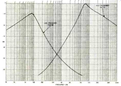
Fig. 12--Bandwidth Controller sensitivity vs. frequency.
Applications
The Dynamic Noise Filter achieves 10-11 dB of noise reduction on tape program material by performing as a constant gain filter whose instantaneous bandwidth is a function of the program content. It has the advantage over other noise reduction methods in its ability to reduce noise arising anywhere in a system ahead of the filter. In contrast, the Dolby Laboratories Noise Reduction System and the Burwen Laboratories Noise Eliminator are both designed to prevent the recording system from introducing noise into the program material but they are not designed to improve existing noisy program material.
For live recording on 16 tracks followed by a two-track tape master and then a two-channel disc, 18 channels of the Dolby Laboratories Noise Reduction System or the Burwen Laboratories Noise Eliminator are normally used. By recording nonstandard signals on the tape the former achieves 10 dB noise reduction and the latter as much as 50 dB. Alternatively, the signal can be recorded on the 16-track machine and then on the two-track machine in normal manner without noise reduction and played through a two-channel Dynamic Noise Filter inserted before the tape duplicating equipment or a disc cutter.
The range of applications for the Dynamic Noise Filter is just now being explored. Potential exists in the AM, FM, and television broadcast fields as well as in theatre sound systems, and rerecording of historic material. For the audio engineer the Dynamic Noise Filter is a new, versatile, and economic tool by which he can control the noise present in his environment, his equipment, his recordings, and his program material.
References
1. Burwen, R. S., "A Dynamic Noise Filter," Journal of the Audio Engineering Society, Volume 19, No. 2, page 115, February, 1971.
2. Burwen, R. S., "110 dB Dynamic Range For Tape," AUDIO, page 49, June, 1971.
3. Dolby, R. M., "An Audio Noise Reduction System," Journal of the Audio Engineering Society, Volume 15, No. 4, page 383, October, 1967.
4. Scott, H. H., "Dynamic Suppression of Phonograph Record Noise. Electronics, December, 1946.
5. Scott, H. H., "Dynamic Noise Suppressor," Electronics, December, 1947.
==========
(adapted from Audio magazine, Jun. 1972)
Also see:
A Peak-Reading VU Meter With Compensation For Tape Saturation (Oct. 1972)
Noise Reduction Techniques (Oct. 1972)
Dolby B-Type Noise Reduction System (Sept. 1973)
Dolby B-Type Noise Reduction System--Part 2 (Oct. 1973)
Introducing Dolby S-Type Noise Reduction (Jun. 1990)
EQ & NR: Striking A Balance (Aug. 1988)
Deck to Deck Matching and NR: Straightening the Mirror (Aug. 1986)
Build this Variable-Frequency Power Source (Jan. 1970)
= = = =