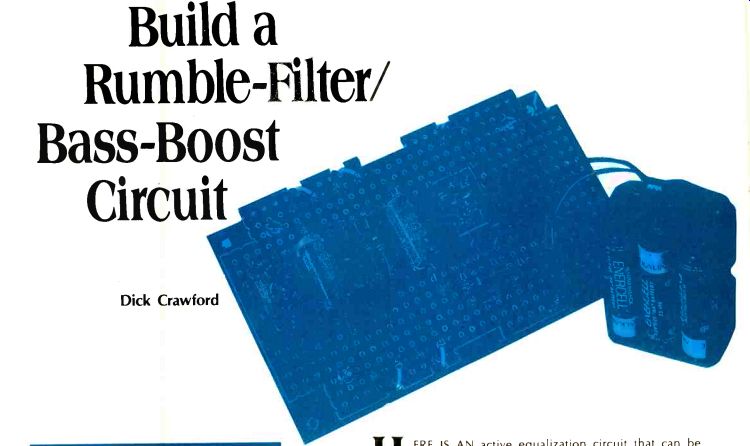
by Dick Crawford
Example #2: Rumble Filter
1--From Fig. 4 (boost vs. R2/R1) determine ratio of R2/R1 for desired boost. In this case, no boost is desired and R2/R1=0.
2--From Fig. 5 or Fig. 6 determine either the peak frequency or the -3 dB frequency. In this case there is no peaking, so the -3 dB frequency is 43 Hz.
3--Determine the scaling factor by dividing the frequency determined in Step 2 (above) by the desired frequency. Let's assume the desired -3 dB cutoff frequency is 20 Hz. Scaling Factor = 46 Hz 20 Hz = 2.3
4--From the scaling factor, determine the correct value of Cl and C2. C1=C2=0.047 x scaling factor = 0.047 x 2.3 = 0.11 µF (Use either 0.10 µF or 0.12 µF).
When the ratio of R2 to R1 is two, the circuit acts as a rumble filter with no bass boost. In technical terms this frequency response is a second-order Butterworth high-pass filter.
The interesting thing happens when the ratio of R2 to R1 is made larger than two. Several of these conditions are plotted in Fig. 2. Notice that as the radio is increased, there is a low-frequency peaking of the response. The greater the ratio, the more the peaking. Also, the greater the ratio, the narrower the peaking. And, the greater the ratio, the faster the cutoff slope below the peak frequency.
Circuit Limitations
What about the limitations of the circuit? It is a relatively narrowband circuit, and while this is generally desired for active equalization in the bass region, it is not the type of circuit for use as a tone control. Furthermore, it is only really suitable for about 13 decibels of boost. Beyond that, the peaking of the boost gets so narrow that adjustment to the speaker's characteristics gets very difficult. Also, there are practical problems in the circuit itself beyond this amount of boost. If you need more boost and want to use this circuit, I suggest that you use two in series. The circuit is designed for use at about the one volt level, that is, the level at which most high-level inputs (tape recorders, tuners, etc.) operate.
At the one volt level, the signal-to-noise ratio is greater than 80 decibels. The distortion, for both second and third harmonic distortion components, is shown in Fig. 3 for various output signal levels. This was with 12 decibels boost at 50 Hz and should represent the worst case as far as circuit design goes. But there is a variation in performance of monolithic operational amplifiers, such as the 741 or 301A, as regards to distortion performance. This is hinted at in the rather wild variation of third harmonic distortion in the sample tested.
However, my experience has shown that the total harmonic distortion from this circuit, regardless of the integrated circuit used, should not exceed 0.1%. Design Adoption
Supposing that you wanted to build the circuit of Fig. 1, how would you start? Well, for one thing, the frequency response information could be plotted in more useful forms, and so it is in Figs. 4, 5, and 6.
Figure 4 shows the amount of boost at the peak in decibels as a function of the ratio of R2 to Rl. Figure 5 shows the frequency at which this peak occurs, again as a ratio of R2 to R1. Figure 6 shows the lower 3 dB point, that is, the frequency at which the frequency response is down 3 decibels from the response at 1 kHz, and this is also plotted as a function of the ratio of R2 to R1.
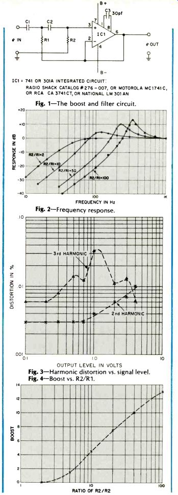
Fig. 1-The boost and filter circuit.
Fig. 2-Frequency response.
Fig. 3-Harmonic distortion vs. signal level.
Fig. 4-Boost vs. R2/R1.
Let's take a hypothetical case and see how the information in these graphs can be used to design the desired circuit.
Suppose that a boost of 6 decibels is desired at 40 Hz. From Fig. 3 we see that a ratio of 14 is needed to give the desired 6 decibel boost. From Fig. 4 we see that, with the values of the components as given in Fig. 1, for a ratio of 14 the peak response is 135 Hz. But our goal for this peak is 40 Hz, so we have to "scale" the values of the components.
When an electrical engineer speaks of scaling, he is usually not referring to a finny fish or some craggy cliff. What he means is changing the values of a set of components so as to accommodate a new set of conditions. In the case at hand, we want to scale the circuit to the new frequency of 40 Hz while maintaining the ratio of R2 to R1 at 14. We can do this by changing either the resistors, the capacitors, or both. I recommend changing the value of the capacitors. If we wish to lower the frequency at which the peak response occurs, we have to increase the value of both of the capacitors in Fig. 1. If we double the value of the capacitors, the frequency of the peak boost will halve. In the case at hand, we wish to lower the peak frequency from 135 to 40 Hz, a scaling factor of 3.38. This means that the capacitors (C1 and C2 of Fig. 1) must be increased to 3.38 times the value shown in Fig. 1, or 0.159µF. This is not a common value, so we will bend a little and choose the closest standard value of 0.15 µF. Another example is shown in the accompanying box. In this case the desired response is that of a rumble filter, that is, no boost-just a fast cutoff. Notice the steps in the design cycle. If you are interested in designing your own circuit, suggest that you try repeating the example of Fig. 7 so that you are sure you understand the procedure.
Notes on Parts
The components are non-critical, and 10% tolerance on capacitors and resistors is adequate. The integrated circuit can be either the 741 or 301A. None of the voltages exceeds 15 volts, so power dissipation or voltage ratings becomes non-critical. Vector board, punched at 0.1 inch intervals, is very convenient for assembly. Any electronic supply house, such as your local Lafayette or Radio Shack stores, should be able to supply these parts.
Power supplies? Well, if you are just experimenting and don't want to invest very heavily until you have decided that this is what you really want, your answer is simple. A pair of 9-Volt transistor radio batteries, such as those found in every drug and grocery store, is your answer. The circuit of Fig. 1 will work very well when using a 9-Volt battery for B plus and another 9-Volt battery for B minus. While some 50 hours or so of operation can be expected per set of batteries, be sure to include an on-off switch for the batteries so that their life will be extended.
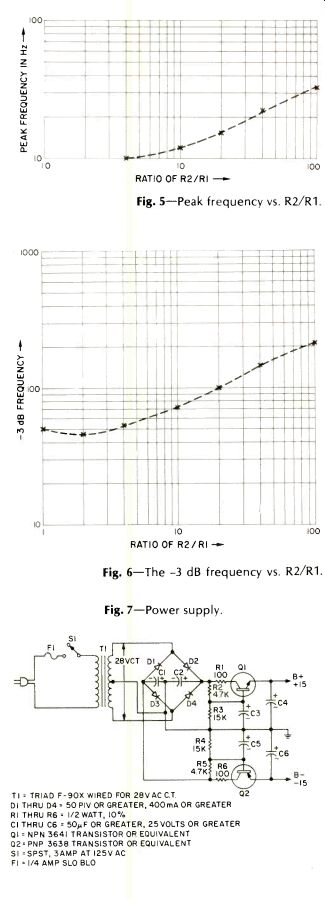
Fig. 5-Peak frequency vs. R2/R1.
Fig. 6-The-3 dB frequency vs. R2/R1.
Fig. 7-Power supply.
T1= TRIAD F-90x WIRED FOR 28VAC C.T. 0 D1 THRU D4 = 50 PIV OR GREATER, 400mA OR GREATER
R1 THRU R6 1/2 WATT, 10°/. C1 THRU C6 = 50µF OR GREATER, 25 VOLTS OR GREATER
Q1 = NPN 3641 TRANSISTOR OR EQUIVALENT
Q2. PNP 3638 TRANSISTOR OR EQUIVALENT
S1 =SPST, 3AMP AT I25V AC
F1 =1/4 AMP SLO BLO
For those who want a more permanent power supply, that shown in Fig. 7 should suffice. There is nothing magical about this circuit, and any supply giving plus and minus 15 Volts with low ripple will be adequate. The power drain is only a few milliamperes.
Two of the equalizer circuits are needed for stereo; they go between the preamplifier output and the power amplifier. Some integrated amplifiers and some preamplifiers have a set of connectors for active equalizers, and, if you are so blessed, that is where this type of equalizer goes.
I find that most everybody (except the neighbors!) likes lots of bass with their hi-fi. Active equalization is one way to get more bass, but, again, be careful in your experiments. In the long run, though, you are the final authority. If you want more bass, give this circuit a try.
Bibliography
1--Audio, November, 1973, contains two articles on loudspeaker equalization.
2-Audio, August, 1975, pg. 30, "A.N. Theile-The Sage of Vented Speakers."
3--R.H. Small, "Closed Box Loudspeaker Systems," Journal of The Audio Engineering Society; Dec., 1972, and Jan./Feb., 1973.
4--R.H. Small, "Vented Box Loudspeaker Systems," Journal of The Audio Engineering Society; June, July/August, September and October, 1973.
5--R.H. Small, "Passive-Radiator Loudspeaker Systems," Journal of The Audio Engineering Society, October and November, 1974.
(Audio magazine, 1976)
Also see:
Equipment Profiles (June 1976)
Energy-Time Test/Richard C. Heyser
Making Records/Ralph Cushino
= = = =