This section (Section A) describes symptoms of problems you might encounter. Then, you are told which Sections contain the troubleshooting and repair guide lines for that symptom.
General Television Problems
Arcing. (See Section 2, Section 4 and Section 8.)
Check:
1. The high voltage circuits.
2. The anodes in the CRT.
3. The flyback transformer.
4. For excessive voltage, especially at the CR1 anodes.
5. For dirty connections.
6. The CRT for cracks.
7. The high-voltage cable and plug.
B+ fuse blows. (See Section 7.)
Check:
1. For a shorted transistor or diode.
2. High voltage circuits.
3. The power supply, especially for shorted diodes or filter capacitors, open diodes, filter capacitors, dropping resistors, fuses or switches, leaky filter capacitors or a shorted transformer or choke.
4. For overloaded voltage sources.
Chassis shutdown. (See Section 8.)
Check the flyback transformer and high-voltage circuits ( FIG. 1).
Frequency (channel) drift. (See Section 9.) Check the:
1. IF amplifier.
2. Tuner (FigureA-2).
3. Power supply to the tuner.
Front panel controls (keyboard) do not work. (See Section 10.) Check the keyboard contacts and power supply to the system control circuits.

FIG. 1. A high-voltage shutdown circuit.
Interference in video. (See Section 5 and Section 10.) Check the:
1. Video IF circuits.
2. The video amplifier (Figure 3).
3. Tuner alignment.

FIG. 2. A tuner circuit.
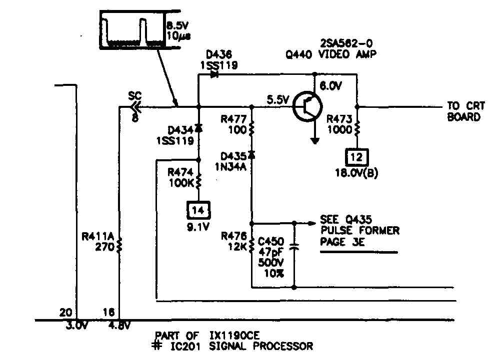
FIG. 3. The last video amplifier.
No channel memory; fails to lock in on one channel. (See Section 10.) Check the:
1. AFT circuits.
2. RAM circuit in the system control IC ( FIG. 4).
3. Tuner alignment.

FIG. 4. A RAM circuit.
Noise in the sync signal. (See Section 7) Check the:
1. Sync separator (Fig. 5).
2. Video detection circuits.
3. Noise reducer (canceller) circuit.
On-screen display (OSD) problems. (See Section 10)
Check the system control circuits, especially the OSD circuits.

FIG. 5. A sync separator circuit.
Power supply turns off. (See Section 4.)
Check:
1. The capacitors, resistors and inductors in the power supply.
2. For excessive voltage.
3. For loss of filtering due to faulty capacitors.
4. For loss of output voltage because of a shorted output capacitor, open-circuited resistor or an open choke.
Raster, picture and sound problems. ( Section 4, Section 5, Section 8 and Section 9.)
Check:
1. The tuner circuits.
2. The IF amplifier (FigureA-6).
3. The AGC.
4. The video detector.
5. The tuner’s mixer.
6. The video processing.
7. For a short in the video amplifier circuits.
8. The power supplies.
9. For very low or very high voltage to the CAT.
10. For shorted or overheated components in the high voltage circuits.

FIG. 6. An IF amplifier connected to an AGC.
Receiving no channels. (See Section 9, Section 10.)
Check the:
1. Tuner circuits.
2. Antenna connection.
3. Solder connections in the tuner and system control IC.
Remote control does not work. (See Section 10.)
Check the:
1. Batteries in the remote control.
2. Infrared receiver circuits in the system control IC.
Reset does not work. (See Section 10.)
Check:
1. The reset circuit in the system control IC (Fig 7).
2. For excessively low voltage.
3. For faulty solder connections or cracked traces in the system control circuit.
Television is inoperative. (See Section 4, Section 7, Section 8 and Section 10.) Check the:
1. Power line cord and plug.
2. Television’s fuses.
3. System control circuits, especially the clock and power pin.
4. Standby power supplies.
5. High-voltage protection circuit.
Television turns on, then turns off. (See Section 4.)
Check for a voltage overload or a high-voltage shutdown.
Ticking sound or a high-pitched squeal. (See Section 8.)
Check the flyback.

Fig. 7. A reset circuit.
Picture Symptoms
A spot (blotch) appears on the screen. (See Section 5.)
Check the CRT’s shadow mask or the degaussing coil.
All colors are incorrect. (See Section 5.)
Check the:
1. Tint control.
2. Chroma processing circuits.
3. CRT.
4. Kine board.
Black bars drift from bottom to top. (See Section 4.)
Check the filters in the power supply ( FIG. 8
Blanking bar appears on the screen. (See Section 7.)
Check the sync separator circuit ( FIG. 9).
Blooming. (See Section 5 and Section 7.)
Check for excessively high voltage, boost, or screen voltage.
“Breathing” picture, vertically and horizontally unstable. (See Section 4.) Check the power supply regulation.

FIG. 8. Filtering. a. Capacitive Filter ; b. Capacitive-Inductive Filter
Brightness problems.
Check:
1. For a high voltage problem.
2. The luminance circuit.
3. The output from the final video amplifier circuit.
Color bleeding. (See Section 5.) Check the comb filter and screen voltage.
Color is too intense. (See Section 5.)
Check:
1 The color control.
2. The color killer.
3. The automatic chroma control (ACC).
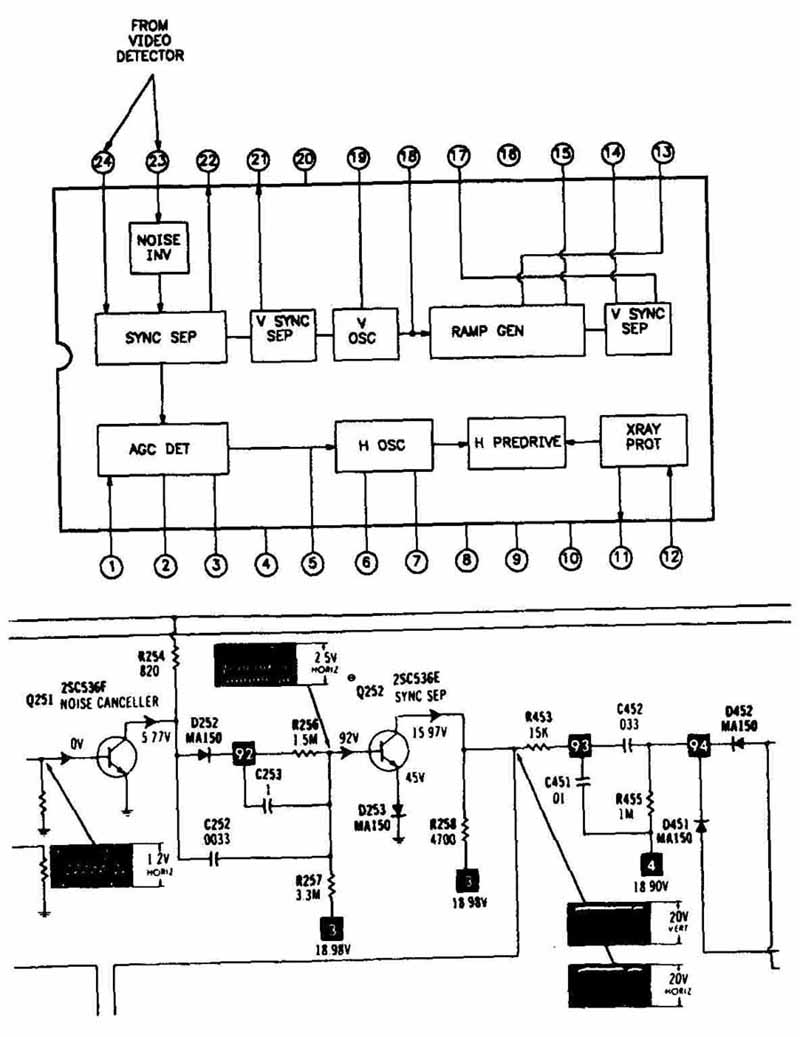
FIG. 9. A sync separator internal to IC.
Colors appear dim. (See Section 5.) Check the:
1. Electron guns for oxidation.
2. CRT for shorting.
3. Luminance circuit.
4. Output from the chroma amplifier circuit.
Horizontal and vertical pincushioning. (See Section 7.)
Check the pincushion circuit.
Horizontal white line on the screen. (See Section 7.)
Check the:
1. Vertical circuits ( FIG. 10).
2. Deflection yoke.
Keystoning. (See Section 7.)
Check the:
1. Deflection yoke.
2. Vertical deflection circuits.
3. Linearity.

FIG. 10. A vertical countdown circuit.

FIG. 11. The last video amplifier
Line pairing or line splitting. (See Section 7.)
Check:
1. For leaking or open diodes, capacitors, or transistors.
2. For a worn potentiometer.
3. The video processing circuits for open connections.
4. The sync separator
5. The high-voltage stages.
Little control of brightness, focus or contrast. (See Section 5, Section 8 and Section 10.)
Check:
1. For low voltage at the heater element.
2. For excessively high voltage.
3. The luminance circuit.
4. Output from the final video amplifier circuit ( FIG. 11).

FIG. 12. The horizontal deflection (drive) circuit.
Loss of horizontal and vertical sync. (See Section 7.)
Check the:
1. Sync separator.
2. Vertical deflection circuits.
3. Horizontal deflection circuits ( FIG. 12).
Loss of horizontal sync; picture tears horizontally. (See Section 5 and 7.)
Check the:
1. APC (automatic phase control) circuit.
2. Sync separator circuit.
3. Horizontal oscillator ( FIG. 13).
Loss of vertical sync; picture rolls up or rolls down. (See Section 5 and 7.)
Check the:
1. Vertical deflection circuits.
2. Sync separator.
Misconvergence problems. (See Section 5.)
Adjust the convergence.
Negative picture. (See Section 5.)
Check the polarity of the diode(s) in the video detector.

FIG. 13. A horizontal oscillator circuit.
No color. (See Section 5.)
Check the:
1. Color 3.58 MHz oscillator.
2. Comb filter.
3. Color sync amplifier.
4. Color killer.
No picture and no sound. (See Section 5 and Section 7.)
Check:
1. The video IF amplifier.
2. For an open or leaky capacitor, transistor or damper diode in the horizontal output circuit.
One color is incorrect. (See Section 5.)
Check the:
1. Tint control.
2. Color signal demodulator.
One or more colors are lost. (See Section 5.)
Check the:
1. Color guns in the CRT.
2. Color controls.
3. Color amplifier.
4. Color signal demodulator.
5. Transistor for the missing color on the Kine board.
Picture does not fill the screen. (See Section 4.)
Check the vertical deflection circuits and for voltage that is too low.
Picture folds or weaves, or has width problems. (See Section 7.)
Check for:
1. A drop in the voltage pulses to the deflection yoke coil.
2. A short in a deflection coil.
Picture is not linear, the top or bottom appear stretched. (See Section 7.) Check the:
1. Vertical oscillator.
2. Vertical output circuit ( FIG. 14).
3. Vertical deflection circuits.
Picture looks like a cartoon; no luminance. (See Section 5.)
Check the video processing circuits or the CR1 circuits.
Picture narrows horizontally. (See Section 8.)
Check for low B÷ voltage.
PIP (picture-in-picture) problems. (See Section 5.)
Check the:
1. PIP circuit.
2. A/V switching circuits ( FIG. 15).
3. Supply voltages to the PIP circuit ( FIG. 16)
4. Video, luminance and color signals at the PIP’s input stage.
5. Sync signal processor.
6. Horizontal and vertical deflection circuits.
Reduced focus or intermittent focus problems. (See Section 5, Section 7 and Section 8.)
Check:
1. The flyback circuit.
2. For an overloaded circuit.
3. For a defective picture tube socket or improper focus voltage.
4. The focus control.
5. For a leaky spark gap assembly.
6. The CRT.
Vertical scan, no horizontal scan; white vertical line appears on the screen. (See Section 7.)
Check the horizontal output circuit.

FIG. 14. A vertical output circuit.

FIG. 15. An A/V switching circuit.

FIG. 16. A PIP block diagram.
Vertical sync signals in the blanking bar. (See Section 7.) Check the sync separator.
Weak or dim picture, reduced brightness. (See Section 7 and Section 8.)
Check:
1. For low voltage at the heater element.
2. For a voltage source that is too low.
A weak hissing sound that can be increased or decreased using the volume control. (See Section 5.)
Check the SIF amplifier.
Crackling or popping. (See Section 6.)
Check:
1. The filter capacitors.
2. The power supplies.
3. For faulty resistors.
Distorted sound or intermittent sound. (See Section 6.)
Check:
1. For a faulty transistor or resistor.
2. The SIF amplifier.
3. The audio processing IC (FigureA-17).
4. The detector coil.
5. For loose wiring and cold solders.
Audio Symptoms

FIG. 17. An audio processing IC.
Hum, putt-pull, or buzz sounds accompanied by a running sync. (See Section 4 and Section 6.)
Check the:
1. Sync separator.
2. AGC circuit.
3. Low-voltage power supply circuits.
4. Filter capacitor.
5. B+ power supply.
Interference in the audio signal. (See Section 6 and Section 10.)
Check the:
1. Audio circuits.
2. Video detector.
3. Tuner circuits.
No second audio program (SAP). (See Section 6.)
Check the:
1. Demodulation in the SAP circuit.
2. Tuner circuits.
No sound, no picture, but there is a raster, and a hum or background noise. (See Section 5.)
Check the:
1. AGC circuit.
2. Tuner circuits.
3. Video detection circuit ( FIG. 18).
4. IF circuit.

FIG. 18. A diode used as a video detector
No sound at all. (See Section 6.)
Check the:
1. Speakers.
2. Volume control circuits, including the audio mode circuits in the system control.
3. Audio processing circuits.
4. IF amplifier.
5. Video detection circuit.
6. Mute circuit.
7. Audio amplifier.
No stereo. (See Section 6.)
Check the:
1. Stereo processing IC.
2. L-R demodulator circuit.
Poor sound quality accompanied by an unstable picture. (See Section 6.) Check the:
1. Filter regulator, capacitors, transistors, resistors, sound alignment in the audio processing circuits.
2. AGC circuits.
3. Tuner alignment.
Ringing sound associated with a picture problem. (See Section 7.) Check for an overloaded circuit.
Sound and picture do not track properly. (See Section 6.) Check the detector coil or sound alignment.
Sound, but no picture or raster. (See Section 5.) Check the:
1. Horizontal circuits and hot transistor.
2. Damper diode.
3. Video processing circuits.
4. CRT.

FIG. 19. A volume control pin.
Squealing or whistling, distorted or intermittent sound, or no sound, even at maximum volume. (See Section 6.)
Check:
1. The filter regulator, capacitors, transistors, resistors, sound alignment in the audio processing circuits.
2. The speaker’s voice coil or the speaker cone.
3. The detector coil.
4. For loose wiring.
5. All solder connections.
6. The power supplies.
Volume control problems. (See Section 10.)
Check the:
1. Audio mode circuits.
2. Power supplies.
3. Volume pin (Fig. 19).
Weak sound. (See Section 6.)
Check:
1. For a leaky or open transistor or capacitor.
2. For a resistance change or voltage that is too high or too low.
3. The speaker cones.
4. The detector coil.